Advanced RF Technologies ADRFTECH001 PCS Repeater User Manual 1
Advanced RF Technologies, Inc. PCS Repeater 1
UserManual.wiki
>
Advanced RF Technologies
>
ADRFTECH001 User Manual
Users Manual
Navigation menu
Upload a User Manual
Namespaces
Wiki Guide
HTML
PDF
Info
Views
User Manual
Discussion / Help
Navigation
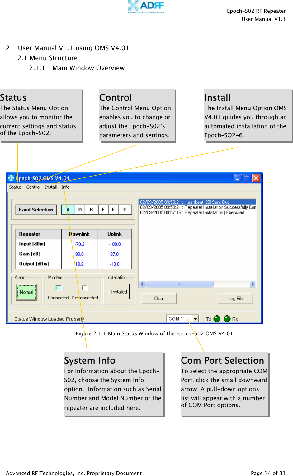
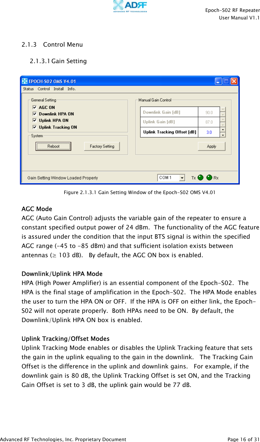
![Epoch-S02 RF Repeater User Manual V1.1 2.1.2 Status Menu The Status Menu is the monitoring window of the Epoch-S02 OMS V4.01. This window enables the user to monitor the status and settings of the Epoch-S02. In other words, no parameters can be changed in the Status Window. To change parameters, use the Control Menu Option. Band Selection Currently selected bands are highlighted. Repeater Input Indicates Input Signal Strength of the Repeater after being amplified by the donor antenna [dBm]. Repeater Output The output of the repeater [in dBm] before being radiated by the server or coverage antenna. Repeater Gain Indicates the gain of the repeater expressed [in dB]. Alarm (Button) The Alarm Button changes color to the corresponding status of the repeater: green for Normal Operation; yellow for Soft Failure; and red for Hard Failure. Click on the Alarm button for detailed information. White Screen In this window, the USER will be able to see heartbeat messages which are sent out periodically. Additionally, the USER will also be able to see any alarms that are generated along with messages once the alarms are cleared as well. Status Bar Displays the status of the repeater (Status Response Success), transmit (TX) and receive (RX) communication lights, and Com port (COM1). The Com Port may be changed by clicking on the arrow next to the COM selection window. Figure 2.1.2 Main Status Window of the Epoch-S02 OMS V4.01Installed Lets you know if the repeater is properly installed or not. Modem Connection PPP connection of the modem Clear Will clear the White Screen Log File Text File for the heartbeat messages and alarm status of the repeater Advanced RF Technologies, Inc. Proprietary Document Page 15 of 31](https://usermanual.wiki/Advanced-RF-Technologies/ADRFTECH001/User-Guide-527965-Page-15.png)