Advanced RF Technologies ADRFTECH001 PCS Repeater User Manual 1
Advanced RF Technologies, Inc. PCS Repeater 1
Users Manual

E
POCH
-S02
U
SER
M
ANUAL
Version 1.1

Epoch-S02 RF Repeater
User Manual V1.1
Version 1.1 (Modified Jan. 31, 2005)
Information in this document is subject to change without notice.
Advanced RF Technologies, Inc. 1996-2004. All rights reserved.
Please send comments to:
E-Mail: info@adrftech.com
Phone: (323) 254-8131
Fax: (323) 254-4928
Address: Advanced RF Technologies, Inc.
Attention: Technical Publications Dept.
2607 Colorado Blvd., Suite 100
Los Angeles, CA 90041
USA
Advanced RF Technologies, Inc. Proprietary Document Page 2 of 31

Epoch-S02 RF Repeater
User Manual V1.1
T
ABLE OF
C
ONTENTS
1. Installation Guide for Epoch-S02 ........................................................................5
1.1 Environmental requirements .........................................................................5
1.1.1 Antenna Separation / Isolation........................................................5
1.1.2 Line of Sight ...................................................................................6
1.2 Warnings and Hazards ..................................................................................7
1.3 Tools and Recommendations for Installation.................................................8
1.4 Epoch-S02 Parts List.....................................................................................9
1.5 Step by Step Instructions for Installation .....................................................10
1.5.1 Repeater Setup .............................................................................10
2 User Manual V1.1 using the OMS V4.01............................................................14
2.1 Menu Structure ...........................................................................................14
2.1.1 Main Window Overview .................................................................14
2.1.2 Status Menu .................................................................................15
2.1.3 Control Menu ...............................................................................16
2.1.3.1 Gain Setting ...................................................................16
2.1.3.2 Alarm Setting .................................................................18
2.1.4 Install Menu..................................................................................19
2.1.4.1 Pre-Installation ..............................................................20
2.1.4.2 Installation .....................................................................21
2.1.5 System Information ......................................................................21
2.2 Using the Epoch-S02 OMS V4.01 ................................................................21
2.2.1 Changing Parameters ...................................................................21
2.3 Alarms........................................................................................................22
2.3.1 General (Fixed Parameter) Alarms .................................................23
2.3.2 Downlink/Uplink Alarms...............................................................24
2.4 Default Control Setting ...............................................................................24
2.4.1 Default General Setting.................................................................24
2.4.2 Default Alarm Setting ...................................................................25
3 Maintenance Guide for Epoch-S02 OMS V4.01 .................................................25
3.1 Periodic Inspection Checklist ......................................................................25
3.2 Preventive Measures for Optimal Operation.................................................25
3.2.1 Recommendations ........................................................................25
3.2.2 Precautions ..................................................................................26
4 Troubleshooting...............................................................................................26
4.1 OMS V4.01 Scenarios..................................................................................26
4.2 Heartbeat Scenarios....................................................................................26
Advanced RF Technologies, Inc. Proprietary Document Page 3 of 31

Epoch-S02 RF Repeater
User Manual V1.1
5 Warranty and Repair Policy............................................................................28
5.1 General Warranty ........................................................................................25
5.2 Specific Product Warranty Instructions ........................................................25
Appendix A : Epoch-S02 OMS V4.01 Installation and Requirements .............................29
A.1 Minimum Requirements..............................................................................29
A.2 Epoch-S02 OMS V4.01 Installation/Startup.................................................29
Appendix B: Specifications...........................................................................................30
B.1 Repeater Specifications...............................................................................30
Advanced RF Technologies, Inc. Proprietary Document Page 4 of 31

Epoch-S02 RF Repeater
User Manual V1.1
1. Installation Guide for Epoch-S02
1.1 Environmental requirements
1.1.1 Antenna Separation / Isolation
Separation between antennas is necessary to prevent oscillation.
Oscillation occurs when the signal entering the system continually
reenters, due to the lack of separation between the input and output
antennas. In other words, the signal is being fed back into the system.
This creates a constant amplification of the same signal. As a result, the
noise level rises above the signal level.
Donor
To prevent feedback, the donor and server antennas must be separated
an appropriate distance to provide sufficient isolation. Isolation is
attained by separating antennas a sufficient distance so that the output
of one antenna does not reach the input of the other. This distance is
dependent on the gains of the repeater and the antennas.
A sufficient isolation value is 13 ~ 15 dB greater than the maximum gain
of the repeater. For example, if the gain of the repeater is 50 dB, then an
isolation of 63 ~ 65 dB or greater is required. In the same manner,
because the Epoch-S02 has a maximum gain of 90 dB, it requires an
isolation of at least 103 ~ 105 dB.
Server
RF Repeater
Figure 1.1.1 RF Repeater Oscillation
Advanced RF Technologies, Inc. Proprietary Document Page 5 of 31

Epoch-S02 RF Repeater
User Manual V1.1
1.1.2 Line of Sight
The donor antenna pointing toward the base station has a narrow beam
antenna pattern. As a result, a slight deviation away from the direction of
the BTS can lead to less than optimum results. In addition, obstacles
between the repeater and BTS may impair the repeater from obtaining
any BTS signal. As a result, the repeater cannot transmit signal to the
coverage area. Therefore, a direct line of sight to the BTS for the Donor
Antenna is vital to the function of a repeater. For the same reason,
placing the coverage antenna in direct line of sight of the coverage area
is also necessary.
DONOR
ANTENNA
BTS
Figure 1.1.2 Line of Sight to the BTS
Advanced RF Technologies, Inc. Proprietary Document Page 6 of 31
Epoch-S02 RF Repeater
User Manual V1.1
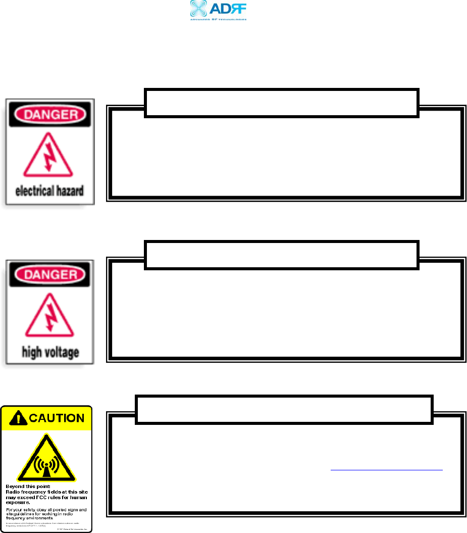
1.2 Warnings and Hazards
Tampering with the modules within the Epoch-S02 Repeater
exposes the user to electric shock and the risk of damaging the
unit. DO NOT TAMPER with modules within the unit. Opening or
tampering with any modules inside the Epoch-S02 will void all
warranties.
WARNING! ELECTRIC SHOCK
Working with the repeater while in operation, may expose the
technician to RF electromagnetic fields that exceed FCC rules for
human exposure. Visit the FCC website at
www.fcc.gov/oet/rfsafety
to learn more about the effects of exposure to RF electromagnetic
fields.
WARNING! EXPOSURE TO RF
In Installing donor or server antennas, avoid close proximity to
overhead power lines or high power components. Contact with
high power components will severely damage the repeater and may
cause serious injury and/or death to the user. Exercise extreme
caution when installing antennas near high power lines.
WARNING! HIGH VOLTAGE
Advanced RF Technologies, Inc. Proprietary Document Page 7 of 31
Epoch-S02 RF Repeater
User Manual V1.1
1.3 Tools and Recommendations for Installation
The following may be necessary (not required) for installation of the repeater:
1. Crescent Wrench or drill with drill bit attachment of …
2. Philips Screw Driver
3. Lift, Ladder, or boom truck
4. Spectrum Analyzer
5. Sweep Tester
6. Signal Generator
7. Pilot Scanner
8. RF Power Meter
9. Voltmeter
10. Coaxial cables
11. Compass
12. Laptop or PC with an RS-232 serial port (with Epoch-S02 OMS V4.01
Software installed)
The list above may vary depending on if brackets are used to install the repeater.
Bring additional tools that may be useful in installation. It is recommended that
two people install the Epoch-S02 Repeater system.
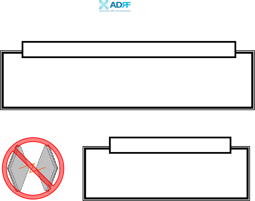
Please maintain a safe distance of 27 cm while operating near the donor and the
server antennas (Assuming the maximum gain of either of the antennas do not
exceed 15 dBi).
MPE WARNING!
Operating the Epoch-S02 with antennas in very close
proximity facing each other could lead to severe
damage to the repeater.
WARNING!
Advanced RF Technologies, Inc. Proprietary Document Page 8 of 31

Epoch-S02 RF Repeater
User Manual V1.1
1.4 Epoch-S02 Parts List
The Epoch-S02 Repeater System includes:
PART ID QUANTITY
1. Epoch-S02 Unit EPOCHSO201 1
2. Repeater I-Bracket (Added Option) ISRB01 1
3. Nuts and Bolts BLTS01 4
4. Screws (Added Option) SC01 8
5. Epoch-S02 OMS V4.01 SO2OMS V4.0101 1
6. Ground Stud GNDSTD01 1
7. Keys KEYS01 4
Advanced RF Technologies, Inc. Proprietary Document Page 9 of 31

Epoch-S02 RF Repeater
User Manual V1.1
1.5 Step by Step Instructions for Installation
1.5.1
r
Repeater Setup
1. Mount the Repeater Bracket (Option)
Position the I-shape repeater bracket (ISRB01) at the desired location.
Using the 8 screws (SC01) provided, fasten the bracket securely.
2. Attach Repeater to the Mounting Bracket (Option)
Using the 4 bolts (BLTS01) provided, fasten the repeater (Epoch-S02) to
the bracket.
3. Open the Epoch-S02
Open the front door of the repeater cabinet by using the key (KEYS01)
provided. There are two locks integrated into the door latches. One key
works for both locks.
** Please keep the cabinet door open fully during the installation until
you are instructed to close the cabinet. When opening the door, wait
until the latch clicks to prevent inadvertent closure of the doo .
4. Connect the Power Source and Ground Wire
Make sure that the power switch inside the repeater is off before
connecting the power cable. Connect the power cable to the power
source. Connect the ground wire (GNDSTD01) to the ground connector.
** Before connecting the power cable to the power source, make sure that
the voltage source is 110 V.
5. Connect the Donor Antenna
Connect one end of the cable to the Donor Antenna and the other end to
the repeater Donor on the bottom of the Epoch-S02.
6. Connect the Server Antenna
Connect one end of the cable to the Server Antenna and connect the
other end to the repeater Server on the bottom of the Epoch-S02.
7. Initialize the Epoch-S02
Using RS232 straight through serial cable, connect one end of the cable
to the Epoch-S02’s NMS port located on the bottom of the repeater and
the other end to the laptop’s serial port.
Advanced RF Technologies, Inc. Proprietary Document Page 10 of 31

Epoch-S02 RF Repeater
User Manual V1.1
8. Turn the Epoch-S02 on
Make sure that the Donor and Server antennas and the power cable are
securely connected to the correct ports. Turn the power switch on,
located inside the repeater.
9. Start the Epoch-S02 OMS V4.01 Program
Open the Epoch-S02 OMS V4.01 program. You will see the
Main Sta us
Window
.
t
l
t
** For more detailed information on the Epoch-S02 OMS V4.01, please
refer to section 2.
10. Select your Com port
From the Main Status Window of the OMS V4.01, select the correct Com
port setting at the lower right hand side of the window.
** P ease make sure that both communication status lights, the TX and
the RX on the bottom of the window, are blinking periodically. A green
blinking TX light indicates that the data is being transmitted from the
laptop/PC to the Epoch-S02. A green blinking RX light indicates that the
data is being retrieved from the Epoch-S02 to the lap op/PC.
** If either the TX or the RX status light is not blinking, check the Com
port setting of your laptop and choose the port to which serial port is
assigned. For more information, refer to section 4, “Troubleshooting.”
** Before proceeding to the next step, please close the cabinet door
(don’t lock) at this time in order to avoid inadvertent RF feedback going
inside the repeater.”
11. Go to the Install Menu
Now with the blinking TX and RX status lights, go to the
Install
menu.
You will see the following window:
Advanced RF Technologies, Inc. Proprietary Document Page 11 of 31
Epoch-S02 RF Repeater
User Manual V1.1
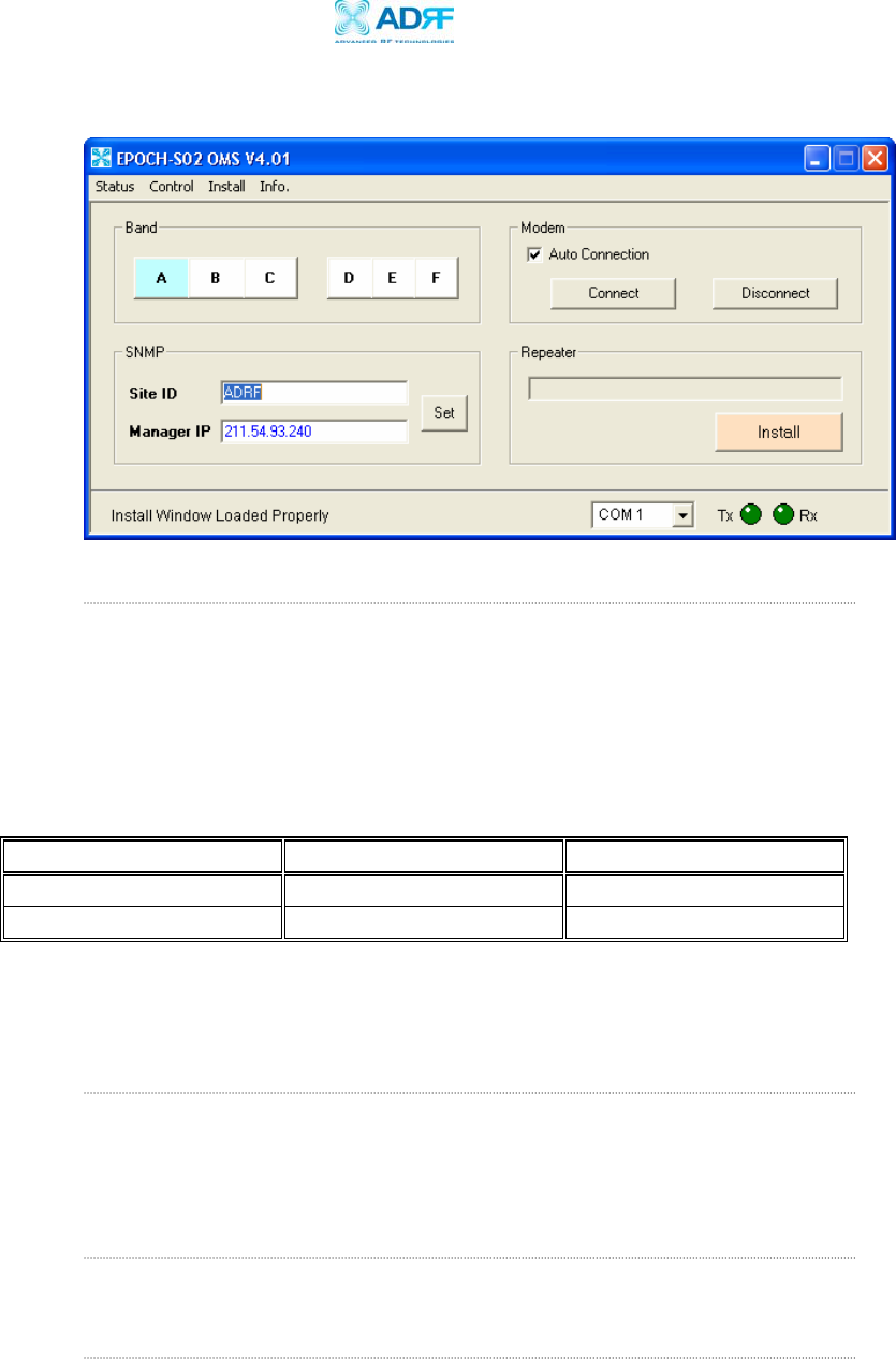
Figure 1.5.1 Installation Window of the Epoch-S02 OMS V4.01
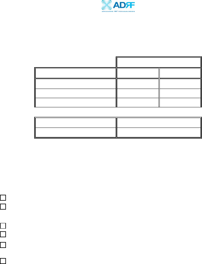
12. Select the desired band or bands
Select the desired band or bands by clicking the appropriate buttons.
You can deselect the undesired band or bands by clicking the button
again. You can select among 15 band combinations; A, B, C, D, E, F, AD,
AE, AF, BD, BE, BF, CD, CE and EF. Neither two 5 MHz bands, e.g., DE nor
two 15 MHz bands, e.g., AB, are allowed. The default band is A.
Control Item Action Setting Value
15 MHz Band Band Selection A/B/C
5 MHz Band Band Selection D/E/F
NOTE: Only one 5 MHz band and one 15 MHz band can be chosen
simultaneously (i.e. A and D, B and E, etc.; not A and B, E and F, etc.).
13. Provide SNMP Information
Type in the Site ID and the Manager IP address as given to you by Sprint
PCS. Once both the parameters are typed in, you must click “Set” for it to
be executed.
14. Check the Modem Connection
Check the “Auto Connection” box and then click on “Connect.”
Table 1.5.1 15 MHz and 5 MHz Band Options
15. Click on Install
After the first three steps, click on “Install.” This installation process will
take a few minutes.
Advanced RF Technologies, Inc. Proprietary Document Page 12 of 31

Epoch-S02 RF Repeater
User Manual V1.1
16. Check the Front LED Panel
Check that the Power LED is on (green) and neither Soft Fail LED (yellow)
nor Hard Fail LED is on (red).
** In the case where either soft fail or hard fail is on, refer to Section 2.3.
** You can go to the Status Window of the OMS V4.01 p ogram to view
the basic parameters of the repeate once the repeate has installed
successfully.
r
r r
17. Lock the Epoch-S02 Door
Now you can lock the door using the key provided.
CONGRATULATIONS!! The Epoch-S02 Installation process is complete.
The Epoch-S02 is now extending coverage!
Advanced RF Technologies, Inc. Proprietary Document Page 13 of 31
Epoch-S02 RF Repeater
User Manual V1.1
2 User Manual V1.1 using OMS V4.01
2.1 Menu Structure
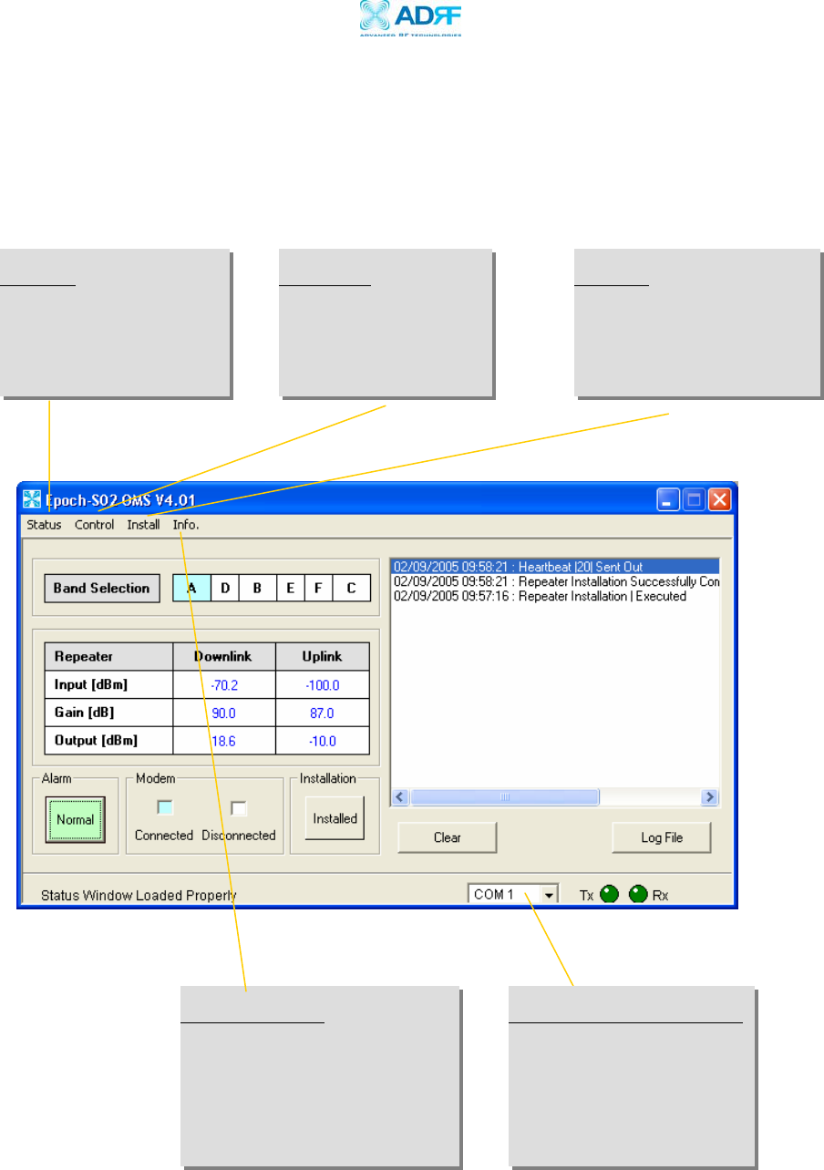
2.1.1 Main Window Overview
Status
The Status Menu Option
allows you to monitor the
current settings and status
of the Epoch-S02.
Control
The Control Menu Option
enables you to change or
adjust the Epoch-S02’s
parameters and settings.
Install
The Install Menu Option OMS
V4.01 guides you through an
automated installation of the
Epoch–SO2-6.
Com Port Selection
To select the appropriate COM
Port, click the small downward
arrow. A pull-down options
list will appear with a number
of COM Port options.
System Info
For Information about the Epoch-
S02, choose the System Info
option. Information such as Serial
Number and Model Number of the
repeater are included here
.
Figure 2.1.1 Main Status Window of the Epoch-S02 OMS V4.01
Advanced RF Technologies, Inc. Proprietary Document Page 14 of 31
Epoch-S02 RF Repeater
User Manual V1.1
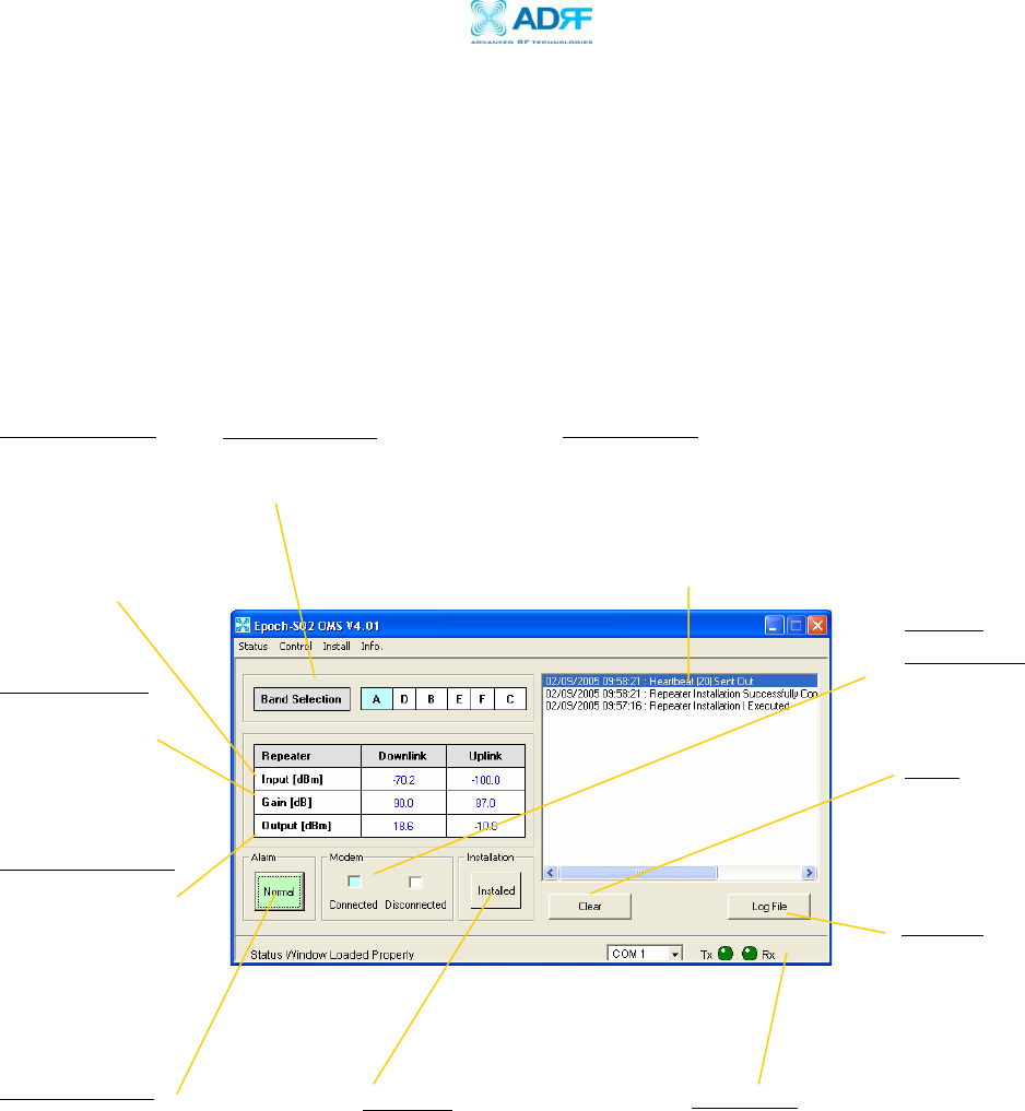
2.1.2 Status Menu
The Status Menu is the monitoring window of the Epoch-S02 OMS V4.01.
This window enables the user to monitor the status and settings of the
Epoch-S02. In other words, no parameters can be changed in the Status
Window. To change parameters, use the Control Menu Option.
Band Selection
Currently selected bands
are highlighted.
Repeater Input
Indicates Input
Signal Strength of
the Repeater after
being amplified by
the donor antenna
[dBm].
Repeater Output
The output of the
repeater [in dBm]
before being radiated
by the server or
coverage antenna.
Repeater Gain
Indicates the gain
of the repeater
expressed [in dB].
Alarm (Button)
The Alarm Button changes color
to the corresponding status of
the repeater: green for Normal
Operation; yellow for Soft
Failure; and red for Hard Failure.
Click on the Alarm button for
detailed information.
White Screen
In this window, the USER will be able to see
heartbeat messages which are sent out periodically.
Additionally, the USER will also be able to see any
alarms that are generated along with messages
once the alarms are cleared as well.
Status Bar
Displays the status of the repeater (Status
Response Success), transmit (TX) and receive
(RX) communication lights, and Com port
(COM1). The Com Port may be changed by
clicking on the arrow next to the COM
selection window.
Figure 2.1.2 Main Status Window of the Epoch-S02 OMS V4.01
Installed
Lets you know if the
repeater is properly
installed or not.
Modem
Connection
PPP connection of
the modem
Clear
Will clear the
White Screen
Log File
Text File for the
heartbeat messages
and alarm status of
the repeater
Advanced RF Technologies, Inc. Proprietary Document
Page 15 of 31
Epoch-S02 RF Repeater
User Manual V1.1
2.1.3 Control Menu
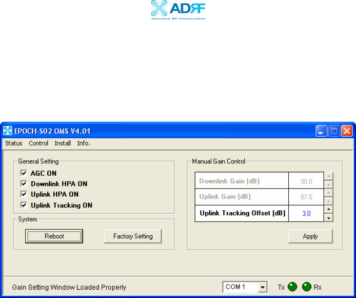
2.1.3.1 Gain Setting
Figure 2.1.3.1 Gain Setting Window of the Epoch-S02 OMS V4.01
AGC Mode
AGC (Auto Gain Control) adjusts the variable gain of the repeater to ensure a
constant specified output power of 24 dBm. The functionality of the AGC feature
is assured under the condition that the input BTS signal is within the specified
AGC range (-45 to -85 dBm) and that sufficient isolation exists between
antennas (≥ 103 dB). By default, the AGC ON box is enabled.
Downlink/Uplink HPA Mode
HPA (High Power Amplifier) is an essential component of the Epoch-S02. The
HPA is the final stage of amplification in the Epoch-S02. The HPA Mode enables
the user to turn the HPA ON or OFF. If the HPA is OFF on either link, the Epoch-
S02 will not operate properly. Both HPAs need to be ON. By default, the
Downlink/Uplink HPA ON box is enabled.
Uplink Tracking/Offset Modes
Uplink Tracking Mode enables or disables the Uplink Tracking feature that sets
the gain in the uplink equaling to the gain in the downlink. The Tracking Gain
Offset is the difference in the uplink and downlink gains. For example, if the
downlink gain is 80 dB, the Uplink Tracking Offset is set ON, and the Tracking
Gain Offset is set to 3 dB, the uplink gain would be 77 dB.
Advanced RF Technologies, Inc. Proprietary Document Page 16 of 31

Epoch-S02 RF Repeater
User Manual V1.1
By default, the Uplink Tracking ON box is enabled and the Uplink Tracking Offset
is set to 0 dB, meaning the uplink gain will always equal the downlink gain.
Control Item Action Setting Value
Uplink Tracking Mode Set Uplink Tracking Mode ON/OFF
Tracking Gain Offset Set Tracking Gain Offset 0 ~ +25 dB @ 0.5 dB Steps
Table 2.1.3.1 Uplink Tracking Mode and Tracking Gain Offset Range
Downlink/Uplink Gain
The gain of the Epoch-S02 is the ratio of the input signal to the output signal.
The gain may be set in both links.
NOTE: The manual gain option is disabled when the AGC Mode is set ON.
System Reboot
Clicking the “System Reboot” button will execute any awaiting actions
immediately that were taken using the OMS program. The changes are reflected
in the status window. Also, clicking on the button will load the repeater with
last saved configurations.
System Factory Setting
The “Factory Setting”
button resets the settings of the repeater to the original
default factory settings as noted in the “Default Control Settings” in Section 2.4.
Advanced RF Technologies, Inc. Proprietary Document Page 17 of 31
Epoch-S02 RF Repeater
User Manual V1.1
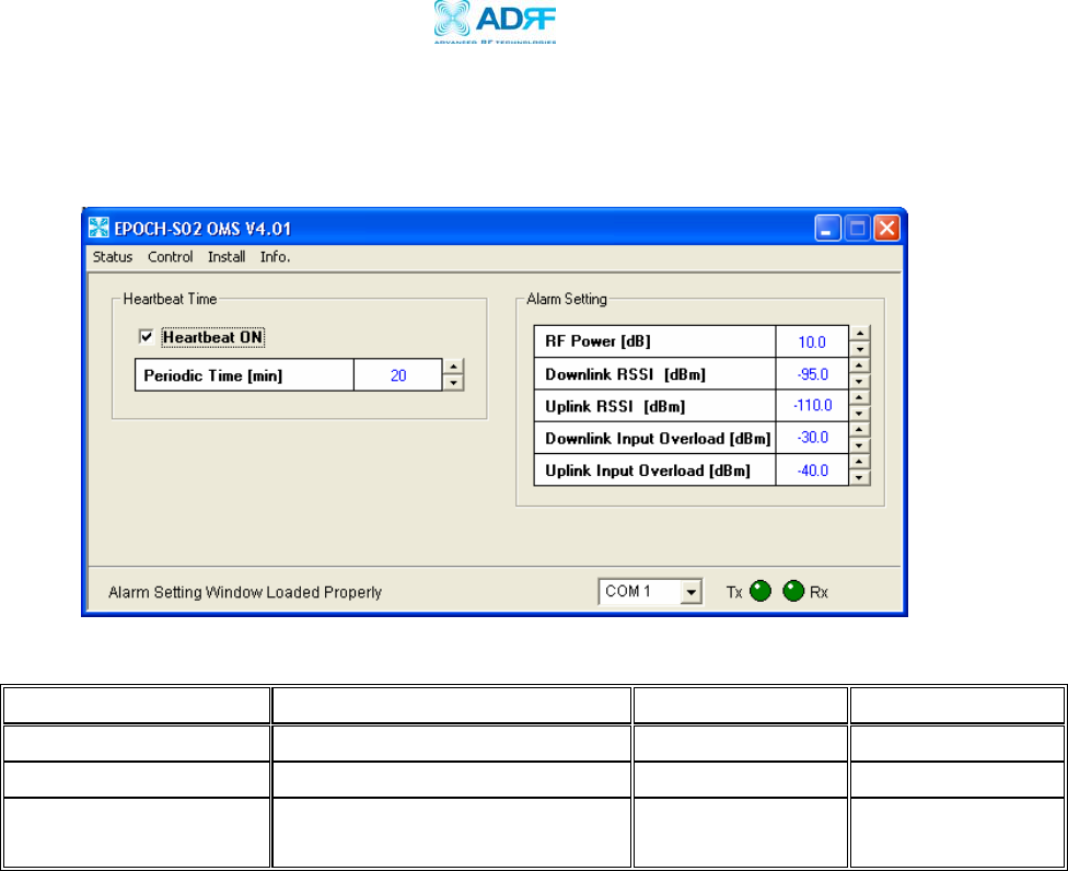
2.1.3.2 Alarm Setting
Figure 2.1.3.2 Alarm Setting Window of the Epoch-S02 OMS V4.01
Control Item Action Downlink Uplink
RF Power Sets Alarm Level 3 ~ 40 dB --
RSSI Sets Low RSSI Alarm Level -120 ~ -30 dBm -120 ~ -30 dBm
Input Overload Sets Donor Input
Overload Level -90 ~ -20 dBm -90 ~ -20 dBm
Table 2.1.3.2 Alarm Threshold Values
Downlink RF Power
The RF Power Alarm is the pilot power difference between the reference pilot
power measured from the embedded modem when the repeater is installed
initially and the current pilot power measured value from the embedded modem
when the repeater is operating (HPA ON). If the difference exceeds the RF Power
value, the alarm will turn on.
RSSI
The RSSI Alarm value is the minimum RSSI value that the Epoch-S02 requires to
ensure optimal coverage. The RSSI Alarm value will turn on when the RSSI is
lower than the threshold value (refer to the RSSI value in the Alarm Setting
window).
Input Overload
An Input Overload Alarm occurs when the input signal strength to the Epoch-S02
exceeds the threshold value (refer to the Uplink/Downlink Input OverIoad values
in the Alarm Setting window).
Advanced RF Technologies, Inc. Proprietary Document Page 18 of 31
Epoch-S02 RF Repeater
User Manual V1.1
Heartbeat
Heartbeat is a periodic message sent out to Sprint PCS’ NOC.
Heartbeat On/Off Set Heartbeat Mode ON/OFF
Heartbeat Time Set Heartbeat Time 1 ~ 60 min @ 1 min Steps
Table 2.1.3.3 Heartbeat Mode and Time Ran
g
e
Heartbeat Mode
The Heartbeat ON box is enabled by default.
Periodic Time
The Periodic Time is the time interval between Heartbeats. The default time is
20 minutes.
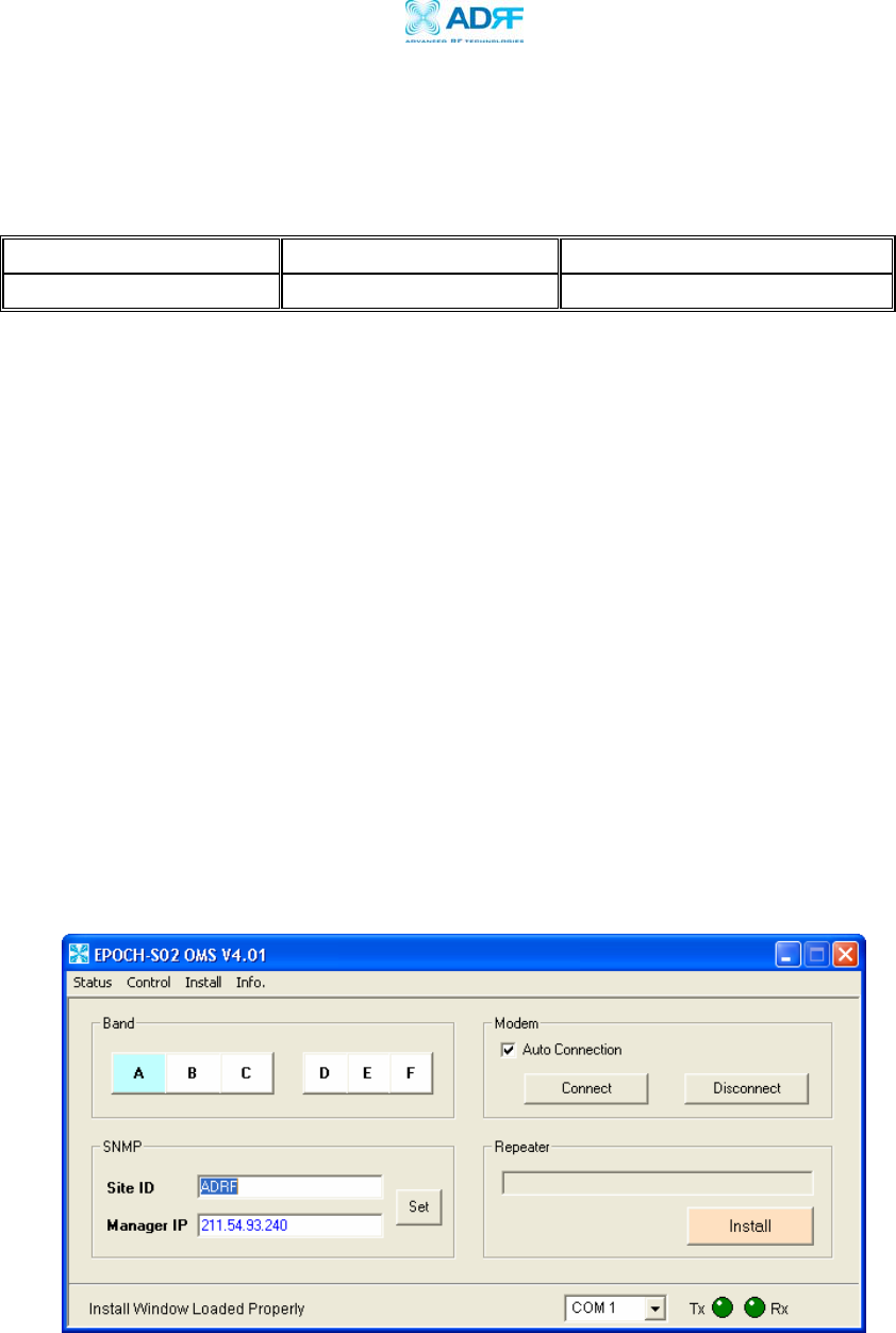
2.1.4 Install Menu
At the time of installation, the installer/technician needs to open the Install Menu
of the Epoch-S02 OMS V4.01. The Install Menu will guide the
installer/technician through a step by step process to properly install the Epoch-
S02 Repeater.
For setup or installation of a repeater, click “Install”
on the menu bar of the Main
Window.
Figure 2.1.4 Install Window of the Epoch-S02 OMS V4.01
Advanced RF Technologies, Inc. Proprietary Document Page 19 of 31

Epoch-S02 RF Repeater
User Manual V1.1
Band
Select the desired band or bands by clicking the appropriate buttons.
You can deselect the undesired band or bands by clicking the button
again. You can select among total 15 band combinations; A, B, C, D, E, F,
AD, AE, AF, BD, BE, BF, CD, CE and EF. Neither two 5 MHz bands nor two
15 MHz bands can be selected at any given time.
SNMP
1. Site ID
The “Site ID” is a unique ID for each site and will be provided by Sprint
PCS.
2. Manager IP
The “Manager IP” address will be provided by Sprint PCS. The repeater
will send alarms to the Sprint PCS’ NOC via the Manager IP address.
Modem
The “Auto Connection” box needs to be checked when the modem is
installed inside the repeater. A 3G wireless modem is used in order to
send the alarms and the heartbeat over the air to Sprint PCS’s NOC.
Repeater
Click the “Install” button and the repeater will setup automatically.
2.1.4.1 Pre-Installation
Prior to the Epoch-S02 Installation, ensure that:
1. The correct Com port is selected.
2. The donor and server antennas are in place.
3. The TX and RX communication status lights are operating.
The TX status light should blink every 3 seconds. A blinking RX
(red) status light indicates that the laptop/PC is retrieving data
from the repeater (Epoch-S02). Similarly, a blinking TX (green)
light indicates that the laptop/PC is transmitting data to the
Epoch-S02.
If neither of the lights is blinking, check the Com port setting of
your laptop/pc by choosing the port to which the serial port is
assigned.
Advanced RF Technologies, Inc. Proprietary Document Page 20 of 31
Epoch-S02 RF Repeater
User Manual V1.1
2.1.4 Installation
For information regarding the use of the Epoch-S02 OMS V4.01 in Installation,
refer to Section 1.5.1, “Repeater Installation” (Starting at number 9).
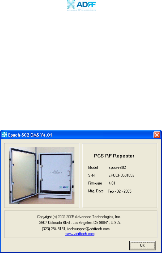
2.1.5 System Information
The System Information Menu Option displays the Model Number, Serial Number,
Firmware Version, Manufacturing Date, and Repeater Installation Date/Time.
Contact information is included along with a link to Advanced RF Technologies,
Inc.’s URL.
Figure 2.1.5 Info. Window of the Epoch-S02 OMS V4.01
2.2 Using the Epoch-S02 OMS V4.01
2.2.1 Changing Parameters
In changing the parameters of the repeater via use of the Epoch-S02 OMS
V4.01, note that the values entered into the OMS V4.01 are limited to the
ranges and modes specified in the Menu Structure section.
The Organizational Chart below shows (alphabetically) the parameters
that can be changed and the location of each parameter in the menu
Advanced RF Technologies, Inc. Proprietary Document Page 21 of 31

Epoch-S02 RF Repeater
User Manual V1.1
structure. The asterisk “*” denotes parameters that apply to both uplink
and downlink.
Control Menu
General Alarm
Setting Setting
Load Default Periodic Time
Manual Gain Control* RF Power
Uplink Tracking Offset RSSI*
Input Overload*
Figure 2.2.1 Variable Parameters in the Epoch-S02 OMS V4.01
2.3 Alarms
The screen shot of the Alarms Window below, can be viewed by clicking the
Alarm
button on the “Main Status Window.” If a soft fail should occur, the alarm of
concern would be highlighted in yellow. In the same manner, the corresponding
hard fail alarm would be highlighted in red. In order to find out what is causing the
alarm(s), simply place the mouse cursor over the highlighted yellow or red alarm box
and a pop up window will appear, displaying the threshold value and the current
measured value. To update the Alarm window, click the “Refresh” button.
Advanced RF Technologies, Inc. Proprietary Document Page 22 of 31

Epoch-S02 RF Repeater
User Manual V1.1
Figure 2.3 All Alarm Parameters from the Main Status
Window of the Epoch-S02 OMS V2.0
In the event of a Hard Failure, the control board will shutdown the HPA for 30
seconds and then turns on the HPA to check for a repeated Hard Fail occurrence. If
the next two occurrences sense a Hard Fail, the control boards will shutdown the
HPA for 1 hour (total of three consecutive hard fails). After 1 hour, the HPA will
automatically come back alive and the control board will check if the Hard Fail alarm
has cleared or not. If it has not, the same process will continue as mentioned above.
2.3.1 General (Fixed Parameter) Alarms
Alarm List Soft Fail Hard Fail Comments
Over/Under Current O O Soft Fail: Less than 1 A @ under current
Hard Fail: More than 6 A @ over current
Over Temperature O O Soft Fail: < 158 ~ 185 °F
Hard Fail: > 185 °F
Synthesizer Lock - O Synthesizer Unlock
VSWR - O > 1.5:1
Low Isolation/Osc. - O Repeater oscillation
Table 2.3.1 General (Fixed Parameter) Alarms of the OMS V4.01
Advanced RF Technologies, Inc. Proprietary Document Page 23 of 31

Epoch-S02 RF Repeater
User Manual V1.1
2.3.2 Downlink/Uplink Alarms
Alarm List Soft Fail Hard Fail Remark
RSSI O -
Input Power Overload O -
Over Power* O O
Downlink
(Forward)
RF Power O -
RSSI O -
Input Power Overload O -
Uplink
(Reverse)
Over Power* O O
Alarms will turn on if the
value is not within operable
limit specified in the
parameters set in the
Control Alarm Setting Menu.
Table 2.3.2 Adjustable Alarm Settings of the OMS V4.01
* The example below distinguishes the difference between an Over Power Soft Failure
and an Over Power Hard Failure.
If the threshold value for the Downlink Over Power parameter was set to 23.0
dBm, a Hard Fail alarm would occur if the Downlink Over Power value was greater
than 24.0 dBm (23.0 +1). Similarly, a Soft Fail alarm would occur if the Downlink
Over Power value was greater than 23.0 dBm but less than 24.0 dBm. The same
example also applies to the Uplink direction.
2.4 Default Control Settings
2.4.1 Default General Setting
Control Item Setting Value
AGC Mode ON
Downlink/Uplink
HPA Mode ON
Uplink Tracking Mode ON
Downlink/Uplink Gain 80 dB
Tracking Gain Offset 0 dB
Table 2.3.3 Adjustable Alarm Settings of the OMS V4.01
1. When Uplink Tracking Mode is set ON, by default, the Tracking Gain
Offset is 0 dB.
Advanced RF Technologies, Inc. Proprietary Document Page 24 of 31
Epoch-S02 RF Repeater
User Manual V1.1
2.4.2 Default Alarm Setting
Setting Value
Control Item
Downlink Uplink
RF Total Power 10 dB --
RSSI -95 dBm -110 dBm
Input Overload -30 dBm -30 dBm
Heartbeat On/Off ON
Heartbeat Time 20 minutes
Table 2.4.2 Default Alarm Parameter Values of the
Epoch-S02 OMS V4.01
3 Maintenance Guide for Epoch-S02 OMS V4.01
3.1 Periodic Inspection Checklist
1. Ensure that the door is closed and locked before inspection.
2. Check for loose connections to the repeater and antennas. If connections
are loose, make sure that all connections are tightly fastened properly.
3. Cables and Connectors are in good condition.
4. Open the Repeater door to check that the Repeater is on.
5. Check that all components inside are intact with no unusual wear (e.g., rust,
dirt, etc.).
6. Ensure that the Repeater brackets (if used) are in good condition and that
the Repeater is securely fastened.
3.2 Preventive Measures for Optimal Operation
3.2.1 Recommendations
• Perform the Periodic Inspection Checklist quarterly or semiannually.
• Always lock the door to the repeater to prevent unauthorized access.
• Tune the Repeater so that amplification is only within the band selected.
In other words, no amplification of unwanted signal(s) outside the
selected band.
Advanced RF Technologies, Inc. Proprietary Document Page 25 of 31

Epoch-S02 RF Repeater
User Manual V1.1
3.2.2 Precautions
• Do not operate the repeater with the antennas in extremely close
proximity as this may cause damage to the repeater.
• Do not shut down the repeater unless absolutely necessary (in the case
where the repeater is a hazard to safety).
• Do not change parameters unless instructed to do so by an authorized
supervisor.
• Do not move the repeater unless instructed to do so by an authorized
supervisor.
• Do not detach any cables to the repeater unless repair of respective
components are necessary.
4 Troubleshooting
4.1 Epoch-S02 OMS V4.01 Scenarios
Tx Rx Explanation
RED RED
The COM Port can not send or receive data. Check the COM
port connection to the computer and the Repeater. Ensure
that the Repeater is on and that the connection to the repeater
is secure.
Blinking
GREEN RED The Repeater is not receiving any commands from the OMS
software. Ensure that the Repeater is on.
Blinking
GREEN GREEN
The Repeater is not receiving any commands from the OMS
software. Ensure that the Repeater is on and that the
connection to the repeater is secure.
Blinking
GREEN
Blinking
GREEN
Successful Connection. The OMS V4.01 and the Repeater are
communicating successfully.
Table 4.1 Tx and Rx LEDs
Note: The Tx/Rx LEDs will blink periodically only on the main status window.
4.2 Heartbeat Scenarios
If the Heartbeat of the Epoch-S02 is not being received by the NOC, it may be
necessary to send a technician to visit the Epoch-S02 site. Scenarios for no
Advanced RF Technologies, Inc. Proprietary Document Page 26 of 31

Epoch-S02 RF Repeater
User Manual V1.1
heartbeats being sent include consistent Hard Failure (as mentioned in the “Alarms”
Section 2.3) in the following areas:
1. Over Current
2. Over Power
3. Over Temperature
Over Current
The “Over Current” Alarm occurs when the input current from the power
source exceeds 6 Amps. In order to lessen the amount of Amperes
drawn by the Epoch-S02, the control board will shut off components that
draw current (i.e. the HPA).
Over Power
The “Over Power” limits for uplink and downlink are set by the user in the
Alarm Setting Window in the Control Menu. A Hard Failure “Over Power”
Alarm occurs when the output of the Epoch-S02 exceeds the limits
entered into the Alarm Parameter Settings (Over Power limit +1 dBm).
Over Temperature
A temperature inside the box greater than 185º F will cause the Epoch-
S02’s control board to shut down the HPA in an attempt to lower the
temperature inside. Though the Epoch-S02 is equipped with a heat sink
to dissipate heat, extreme conditions, such as very hot temperature, are
dealt with by shutting down heat-generating components (i.e. HPA).
1. Prior to visiting the site, know the temperature of the Epoch-S02 site
on the day that the heartbeat stopped being sent.
2. Observe the ambient temperature surrounding the Epoch-S02 site. If
the weather is hot, it is safe to assume that the outdoor temperature
caused the “Over Temperature” Failure.
3. If the outdoor temperature was or is fairly cool, one can assume too
much heat is being generated within the Epoch-S02.
4. Since the HPAs have been shutdown to dissipate heat, it is safe to
evaluate the repeater by unlocking and opening the front door.
5. Evaluate the inside of the Epoch-S02 and check to see that no
unusual wear exists (e.g. burned, blackened areas, etc.). If you detect
these areas, contact Advanced RF Technologies, Inc. in the “Warranty
and Contact Information” section, Section 5.
Advanced RF Technologies, Inc. Proprietary Document Page 27 of 31

Epoch-S02 RF Repeater
User Manual V1.1
5 Warranty and Repair Policy
5.1 General Warranty
Advanced RF Technologies, Inc. warrants to the original purchaser all standard
products sold by Advanced RF Technologies, Inc. to be free of defects in material
and workmanship for the duration of the warranty period of one (1) year from date
of shipment from Advanced RF Technologies, Inc. During the warranty period, at
our option, is limited to repair or replacement of any product that Advanced RF
Technologies, Inc. proves to be defective. This warranty does not apply to any
product, which has been subject to alteration, abuse, improper installation or
application, accident, electrical or environmental over-stress, negligence in use,
storage, transportation or handling.
5.2 Specific Product Warranty Instructions
All Advanced RF Technologies, Inc. repeaters are manufactured to high quality
standards and are warranted against defects in workmanship, materials and
construction, and to no further extent. Any claim for repair or replacement of a
device found to be defective on incoming inspection by a customer must be made
within 30 days of receipt of the shipment, or within 30 days of discovery of a defect
within the warranty period.
This warranty is the only warranty made by Advanced RF Technologies, Inc. and is in
lieu of all other warranties, expressed or implied, except as to title, and can be
amended only by a written instrument signed by an officer of Advanced RF
Technologies, Inc. Advanced RF Technologies, Inc. customer support
representatives are not authorized to make commitments on warranty returns.
In the event that it is necessary to return any product against the above warranty,
please contact the Customer Support Department via e-mail @
customersupport@adrftech.com or by calling (323) 254-8131.
Note: Advanced RF Technologies, Inc. test reports or data indication mean-time-
between failure or other reliability data are design guides and are not intended to
imply that individual products or samples of products will achieve the same results.
These numbers are to be used as management and engineering tools, and are not
necessarily indicative of expected field operation. These numbers assume a mature
design, good parts, and no degradation of reliability due to manufacturing
procedures and processes.
Advanced RF Technologies, Inc. Proprietary Document Page 28 of 31

Epoch-S02 RF Repeater
User Manual V1.1
Appendix A: Epoch-S02 OMS V4.01 Installation and Requirements
A.1 Minimum Requirements
Hardware
PC Platform
CPU: 200 MHz
Memory: 32 MByte
Hard Disk: 6 MByte (free space)
Serial Port: 1Port (RS-232)
CD-ROM Drive
Compatible Operating System
Microsoft Windows 98SE, ME, 2000 (preferred), XP
A.2 Epoch-S02 OMS V4.01 Installation/Startup
Installing the Epoch-S02 OMS V4.01
1. Insert the CD into the CD-ROM drive.
2. On the Desktop, click on
My Computer
.
3. In the
My Computer
window, click on your CD-ROM drive, usually
labeled (D:).
4. Double-click the file labeled
setup.exe
.
5. The Installation Wizard will guide you to the conclusion of the OMS
V4.01 installation process.
Initial OMS V4.01 Startup
1. Attach the PC serial (RS-232) port to the repeater’s (DB9 NMS) port
with the cable (straight through) provided.
2. Open the Epoch-S02 OMS V4.01 software
3. In the Status Window, choose your connection to the repeater: COM1,
COM2, COM3, or COM4 (The default setting is COM1). Refer to
section 4.6.1 for additional information.
4. Click
Status
to update the Status Window.
Advanced RF Technologies, Inc. Proprietary Document Page 29 of 31

Epoch-S02 RF Repeater
User Manual V1.1
Appendix B: Specifications
B.1 Repeater Specifications
ELECTRICAL SPECIFICATIONS
PARAMETERS SPECIFICATIONS COMMENTS
FL 1930 to 1990 MHz Frequency
Range RL 1850 to 1910 MHz
Sub Band Filtering 5 MHz, 15 MHz, or 20 MHz A, D, B, E, F, C, AD, AE, AF,
DB, DC, BE, BF, EC or FC
Operating Frequency Programmable
Frequency Error ≤ +/- 0.1 ppm
System Delay ≤ 5 usec Each Direction
Receiver Dynamic Range -85 to -45 dBm
Maximum Adjacent Band
Signal Level
-45 dBm @ Isotropic Antenna
Repeater Gain 50 to 90 dB
Maximum FL and RL Output
Power
+24 dBm Composite
FL AGC Range 40 dB
RL AGC Range 40 dB
AGC Step Size 0.5 dB
Gain Linearity ≤ +/- 1.0 dB
Gain Flatness ≤ 2.5 dB
Total PA Power Variance ≤ +/- 0.5 dB
≤ -45 dBc @ Fc +/- 885 KHz
In Band Noise ≤ -50 dBc @ Fc +/- 1.98 MHz
Spurious Emission < -13 dBm @ Fc +/- 2.25 MHz
Rho Factor ≥ 0.912
Noise Figure Typical 4 dB @ Maximum Gain
VSWR ≤ 1.5:1
Advanced RF Technologies, Inc. Proprietary Document Page 30 of 31

Epoch-S02 RF Repeater
User Manual V1.1
MECHANICAL SPECIFICATIONS
PARAMETERS SPECIFICATIONS COMMENTS
Cabinet Size 15.75 x 17.72 x 7.85
inches
W x H x D
Cabinet Weight ≤ 50 lbs
Cabinet Mount Type Utility Pole Mount
Antenna N-Type (F)
Coupling SMA (F) 30 dB
Frame Ground Hex Nut (M6)
Connector
Type
Control DB9 (M)
Cooling Convection
Weatherproofing NEMA 4, IP65
POWER SPECIFICATIONS
PARAMETERS SPECIFICATIONS COMMENTS
Main AC Power 100 to 240 VAC
AC Frequency 45 to 65 Hz
Power Consumption ≤ 300 Watts
AC Supply Protection Fuse
Output Voltage 12.0 VDC
Endurance ≥ 2 hour
Main to
Auxiliary
Automatic
Auxiliary to
Main
Automatic
Auxiliary
Power
(Option)
Battery
Protection
Internal Fuse
Grounding External Threaded Stud
ENVIRONMENTAL SPECIFICATIONS
PARAMETERS SPECIFICATIONS COMMENTS
Operating Temperature -22 ˚F to +122 ˚F
Storage Temperature -22 ˚F to +176 ˚F
Humidity 10 to 85%, RH
Advanced RF Technologies, Inc. Proprietary Document Page 31 of 31