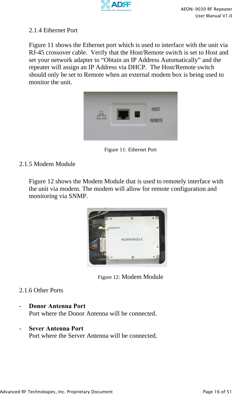
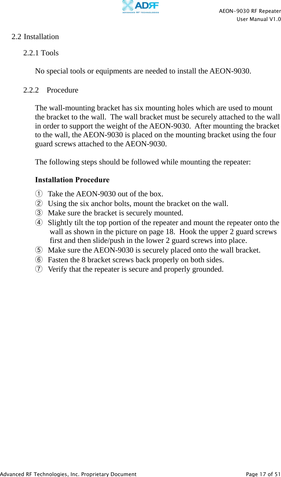
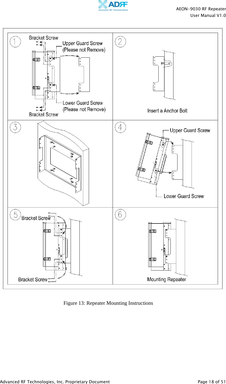
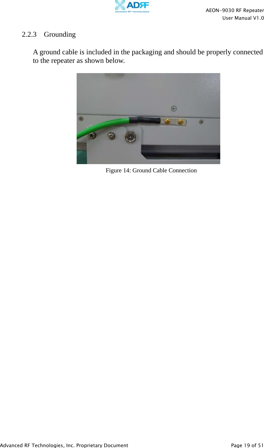
Advanced RF Technologies AEON Digital Dual Band Repeater User Manual
Advanced RF Technologies, Inc. Digital Dual Band Repeater Users Manual
UserManual.wiki
>
Advanced RF Technologies
>
AEON User Manual
Users Manual
Navigation menu
Upload a User Manual
Namespaces
Wiki Guide
HTML
PDF
Info
Views
User Manual
Discussion / Help
Navigation
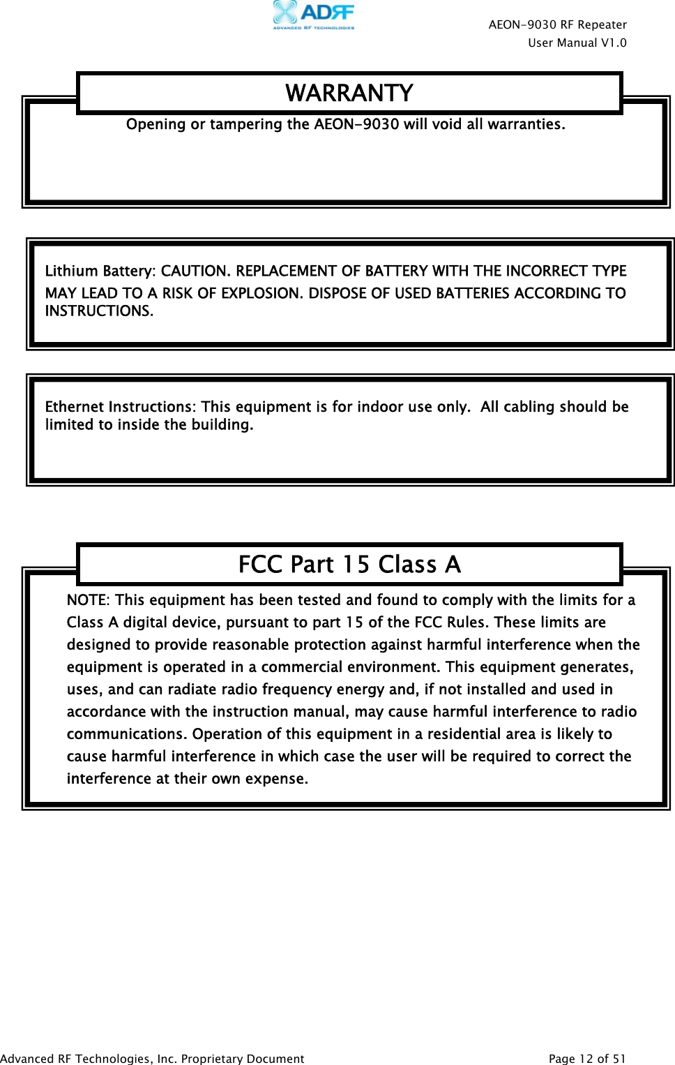
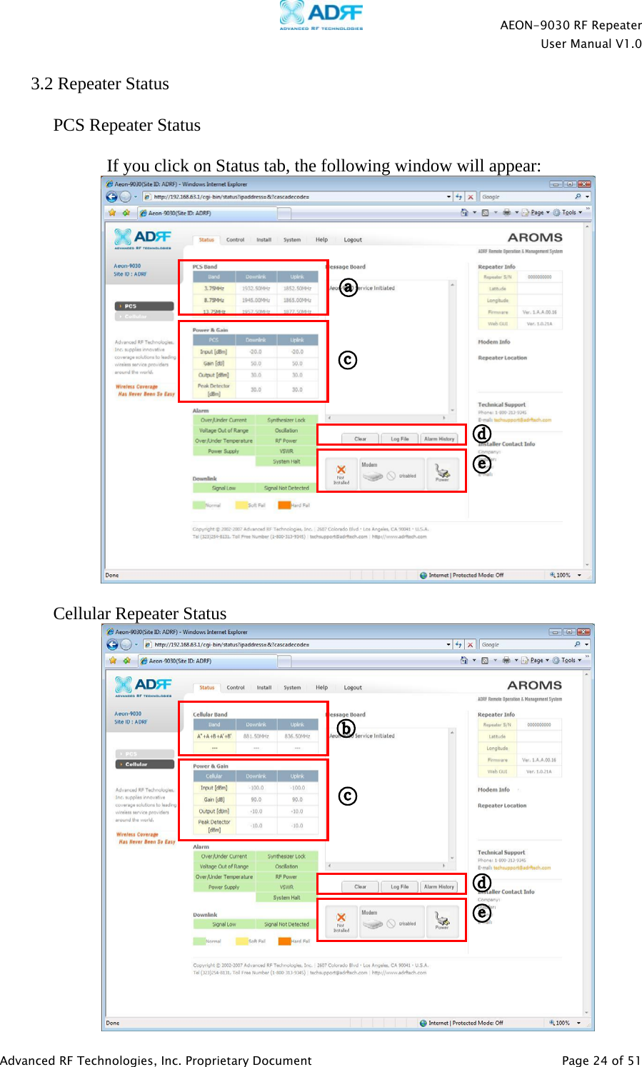
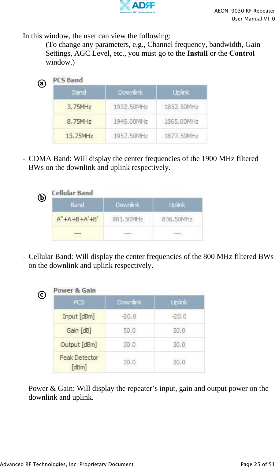
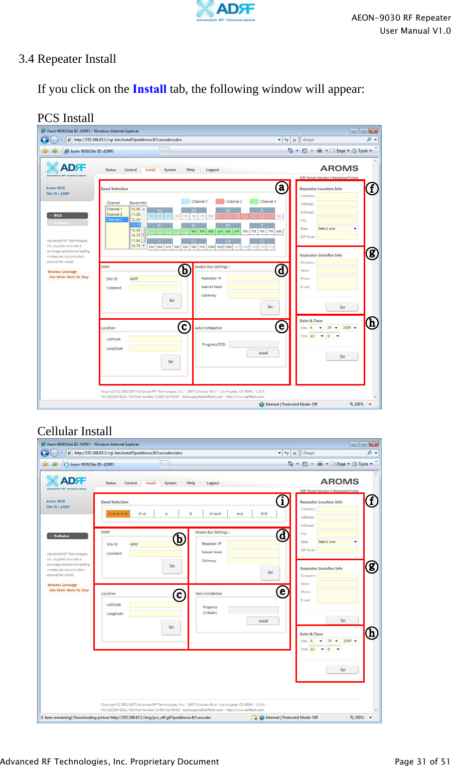
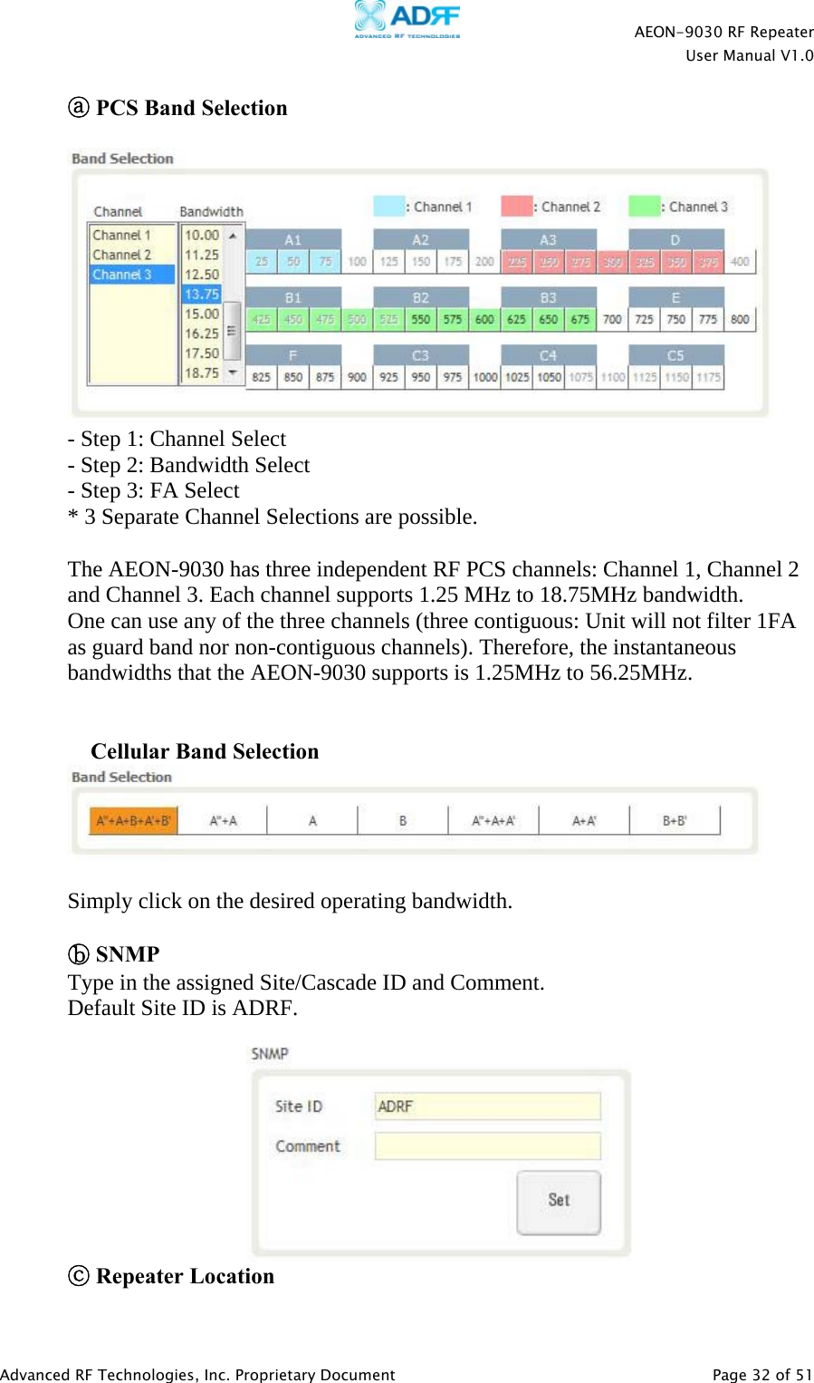
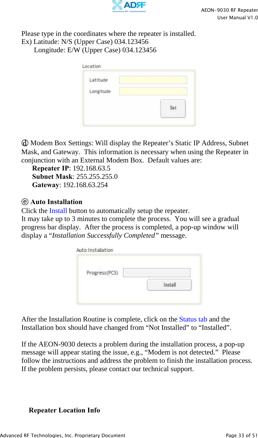
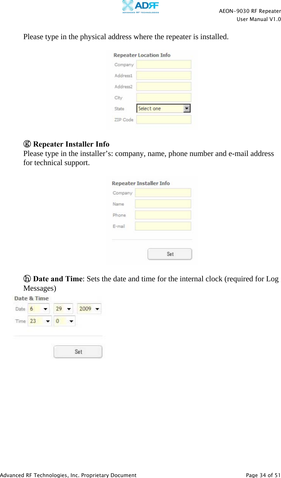
![AEON-9030 RF Repeater User Manual V1.0 Advanced RF Technologies, Inc. Proprietary Document Page 26 of 51 - Clear: Will delete message board contents. - Log File: Will download repeater’s log file. - Alarm History: Will provide additional alarm log for repeater’s status. - Installed icon: Shows the current “Install” status (Installed or Not Installed). - Modem icon: Shows the current modem status (Disabled, Connected, Not connected). - Power icon: Shows the current electric source [AC power, Battery (Shown when an external battery box is installed)].](https://usermanual.wiki/Advanced-RF-Technologies/AEON/User-Guide-1225979-Page-26.png)