Advanced RF Technologies AEON Digital Dual Band Repeater User Manual
Advanced RF Technologies, Inc. Digital Dual Band Repeater Users Manual
Users Manual
AEON-9030 RF Repeater
User Manual V1.0
Advanced RF Technologies, Inc. Proprietary Document Page 1 of 51
AEON-9030
USER MANUAL
Version 1.0
2607 Colorado Blvd.
Los Angeles, CA 90041
USA
Tel: 323-254-8131
Fax: 323-254-4928
www.adrftech.com

AEON-9030 RF Repeater
User Manual V1.0
Advanced RF Technologies, Inc. Proprietary Document Page 2 of 51
Glossary
The following is a list of abbreviations and terms used throughout this
document.
Abbreviation/Term Definition
AGC Automatic Gain Control
ALC Automatic Level Control
AROMS ADRF’s Repeater Operation and Management
System
BTS Base Transceiver Station
CDMA Code Division Multiple Access
CW Continuous Wave (un-modulated signal)
DAS Distributed Antenna System
DL Downlink
Downlink The path covered from the Base Transceiver
Station (BTS) to the subscribers service area
via the repeater
HPA High Power Amplifier
HW Hardware
iDEN Integrated Digital Enhanced Network
IF Intermediate Frequency
LNA Low Noise Amplifier
MS Mobile Station
PLL Phased Locked Loop
PSU Power Supply Unit
RF Radio Frequency
SW Software
UL Uplink
Uplink The path covered from the subscribers service
area to the Base Transceiver Station(BTS) via
the repeater
VSWR Voltage Standing Wave Ratio

AEON-9030 RF Repeater
User Manual V1.0
Advanced RF Technologies, Inc. Proprietary Document Page 3 of 51
Version 1.0 (July 1, 2009)
Information in this document is subject to change without notice.
Advanced RF Technologies, Inc. 1996-2009
All rights reserved.
Please send comments to:
E-Mail: info@adrftech.com
Phone: (323) 254-8131
Fax: (323) 254-4928
Address: Advanced RF Technologies, Inc.
Attention: Technical Publications Department
2607 Colorado Blvd., 1st floor
Los Angeles, CA 90041
USA
www.adrftech.com
AEON-9030 RF Repeater
User Manual V1.0
Advanced RF Technologies, Inc. Proprietary Document Page 4 of 51
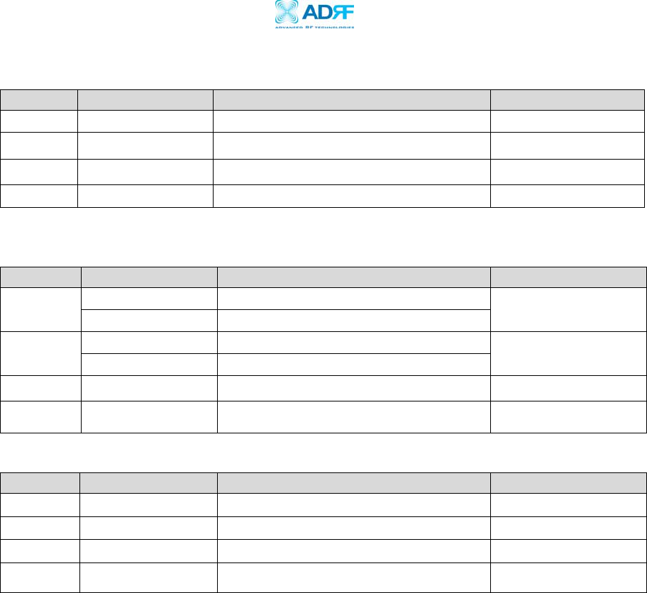
Revision History for Manual
Version Author Description Date
1.0 K.Y.LEE First Generation. July 1, 2009
Revision History for Hardware
Version Author Description Date
1.0 Digital Part First Generation. July 1, 2009
RF Hardware First Generation.
Revision History for Firmware
Version Author Description Date
1.0 Anthony Jang First Generation July 1, 2009

AEON-9030 RF Repeater
User Manual V1.0
Advanced RF Technologies, Inc. Proprietary Document Page 5 of 51
Table of Contents
1. Introduction of AEON-9030 ................................................................................... 7
1.1 Introduction ....................................................................................................... 7
1.1.1 Highlights .............................................................................................. 7
1.1.2 Parts List ............................................................................................... 8
1.1.3 Repeater Quick View ............................................................................ 9
1.2 Warnings and Hazards .................................................................................... 11
2. AEON-9030 Overview ......................................................................................... 13
2.1 Switches & Indicators ..................................................................................... 13
2.1.1 LEDs ................................................................................................... 13
2.1.2 AC Power Switch ................................................................................ 15
2.1.3 Back Up Battery Switch & Battery Port ............................................. 15
2.1.4 Ethernet Port ....................................................................................... 16
2.1.5 Modem Module ................................................................................... 16
2.1.6 Other Ports .......................................................................................... 16
2.2 Installation....................................................................................................... 17
2.2.1 Tools ................................................................................................... 17
2.2.2 Procedure ............................................................................................ 17
2.2.3 Grounding ........................................................................................... 19
2.3 Antenna Separation/Isolation .......................................................................... 20
2.4 Line of Sight ................................................................................................... 21
3. AEON-9030 AROMS Setup ................................................................................. 22
3.1 Repeater/PC Connection Using AROMS ....................................................... 22
3.2 Repeater Status ................................................................................................ 24
3.3 Repeater Control ............................................................................................. 28
3.4 Repeater Install ............................................................................................... 31
3.5 Repeater System.............................................................................................. 35
4. Maintenance Guide for AEON-9030 .................................................................... 37
4.1 Periodic Inspection Checklist ......................................................................... 37
4.2 Preventive Measures for Optimal Operation .................................................. 37
5. AEON-9030 Troubleshooting Guide .................................................................... 38
5.1 Connectivity Guide for LAN .......................................................................... 38
5.2 Troubleshooting Guide for Repeater ............................................................... 41
6. Warranty and Repair Policy .................................................................................. 44
6.1 General Warranty ............................................................................................ 44
6.2 Limitations of Warranty .................................................................................. 44
6.3 Limitation of Damages ................................................................................... 44
6.4 No Consequential Damages ............................................................................ 44
6.5 Additional Limitation on Warranty ................................................................. 44
6.6 Return Material Authorization (RMA) ........................................................... 44
Appendix A: Specifications .............................................................................................. 45
A.1 Electrical Specifications ................................................................................. 45
A.2 Mechanical Drawing ...................................................................................... 46
A.3 Power Specifications ...................................................................................... 46
A.4 Environmental Specifications ........................................................................ 46

AEON-9030 RF Repeater
User Manual V1.0
Advanced RF Technologies, Inc. Proprietary Document Page 6 of 51
A.5 Other Specifications ....................................................................................... 47
Appendix B: Mechanical Drawing ................................................................................... 48
Appendix C: AEON-9030 Overview ................................................................................ 49
C.1 Black Diagram ................................................................................................ 49
C.2 Components .................................................................................................... 50

AEON-9030 RF Repeater
User Manual V1.0
Advanced RF Technologies, Inc. Proprietary Document Page 7 of 51
1. Introduction of AEON-9030
1.1 Introduction
AEON-9030 repeaters enhance indoor wireless coverage in the most effective and
cost efficient way. Intelligent design and versatility make AEON-9030 repeaters
the ideal choice for indoor wireless coverage problems. DSP (Digital Signal
Processing) technology is utilized to achieve the highest level of performance and
filtering agility.
1.1.1 Highlights
• Dual Band (PCS, Cellular)
• Covers the 60 MHz PCS band
• Down Link 30 dBm Composite Output Power
• Up Link 30 dBm Composite Output Power
• 90 dB gain
• 30 dB AGC Range @ 0.5 dB Step
• Adjustable AGC Output Power Level
• Automated installation
• Web GUI connectivity via DHCP
• Band Selectable via Web-GUI
• Can Support Non-Contiguous Bands
• Supports Embedded Wireless Modem
• Supports Network Management Monitoring System via SNMP
• Three independent RF PCS channels Each channel supports 1.25 MHz
to 18.75 MHz bandwidth
• Adjustable FA (3 channels)
• Digital filtering
• Oscillation detection
AEON-9030 RF Repeater
User Manual V1.0
Advanced RF Technologies, Inc. Proprietary Document Page 8 of 51
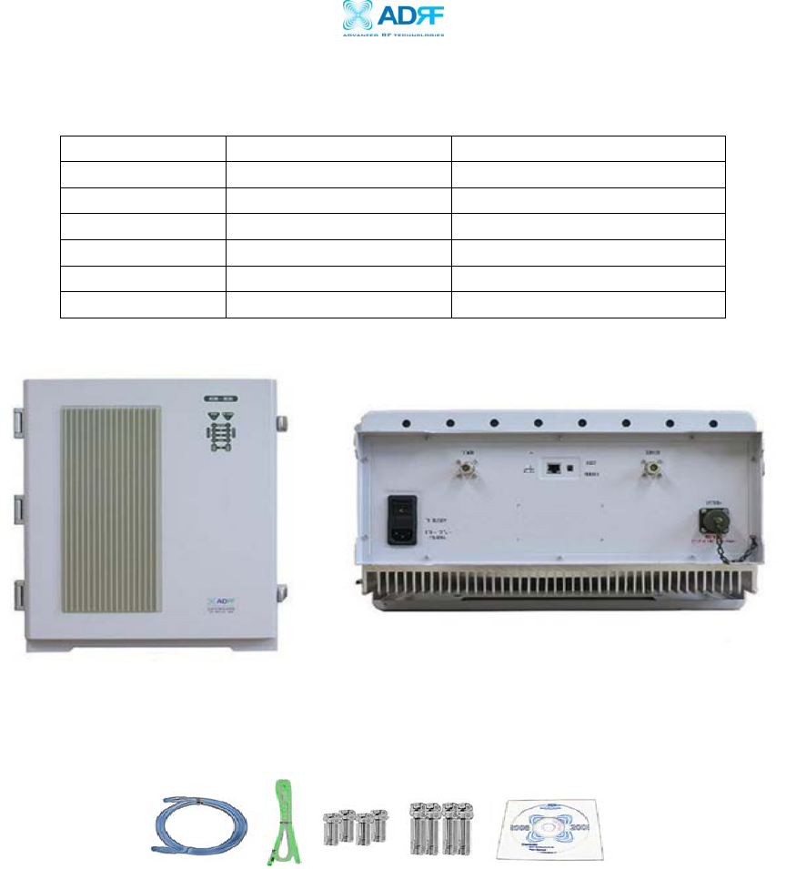
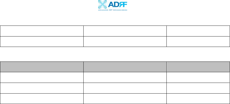
1.1.2 Parts List
Label Qty Description
A 1 AEON-9030 Repeater
B 1 Ethernet Cable (crossover)
C 1 Ground Cable
D 1 Kit (Set of 4) 3/8” Nuts & Bolts
E 1 Kit (Set of 4) 1/2” Nuts & Bolts
F 1 CD**
** CD includes: (1) AEON-9030 User Manual & (2) AEON-9030 Quick
Start Guide
Figure 1: AEON-9030 Repeater Parts List
Table 1: Parts List
B C D E F
A
AEON-9030 RF Repeater
User Manual V1.0
Advanced RF Technologies, Inc. Proprietary Document Page 9 of 51
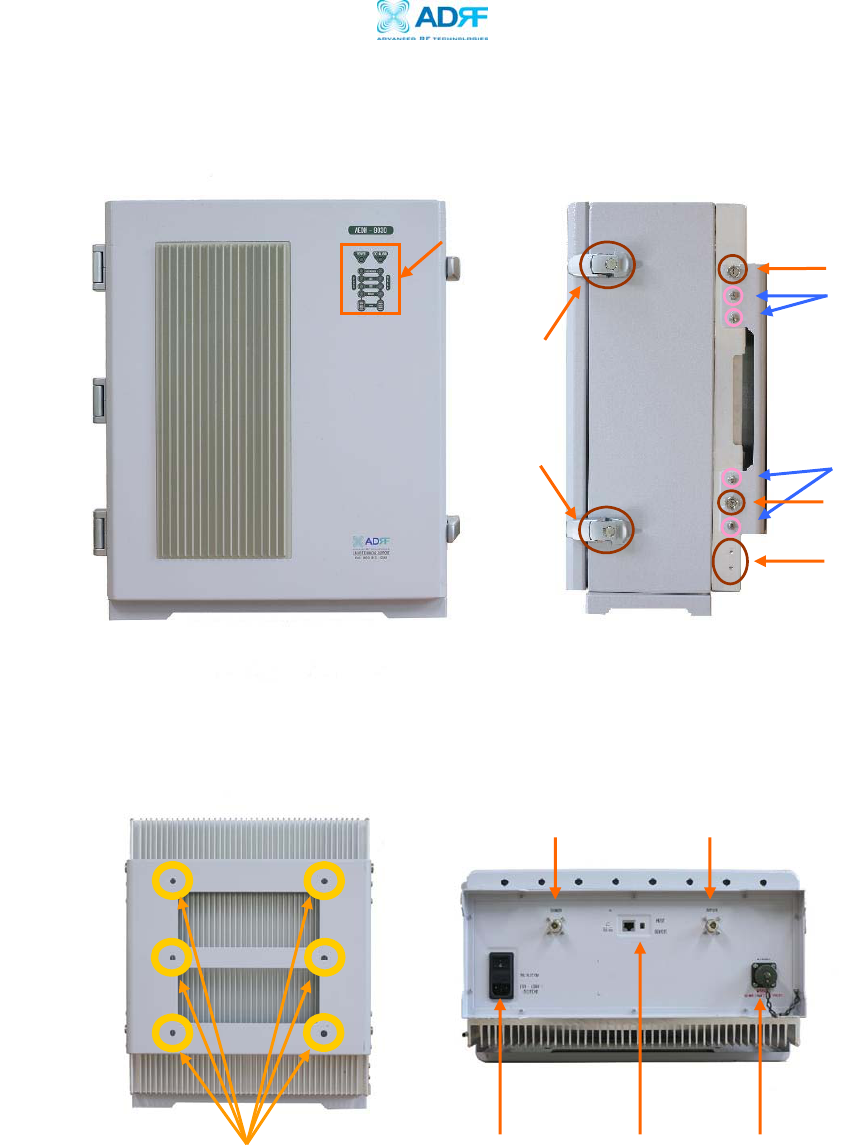
1.1.3 Repeater Quick View
Upper Guard Screw
Ground Hole
(Page 19)
Figure 2: AEON-9030 Front & Side Views
Fi
g
ure 3: AEON-9030 Bac
k
& Botto
m
Views
Door Lock
Lower Guard Screw
(Page 18)
Bracket Screw
(Page 18)
Bracket Screw
(Page 18)
Anchor Bolt
Hole (Page 18)
Donor Antenna
Port (Page 16)
Server Antenna
Port (Page 16)
Ethernet Port
(Page 15) Back Up
Battery Port
(Page 15)
AC Power
Supply Cord
(Page 15)
Display LED
(Page 13)
AEON-9030 RF Repeater
User Manual V1.0
Advanced RF Technologies, Inc. Proprietary Document Page 10 of 51
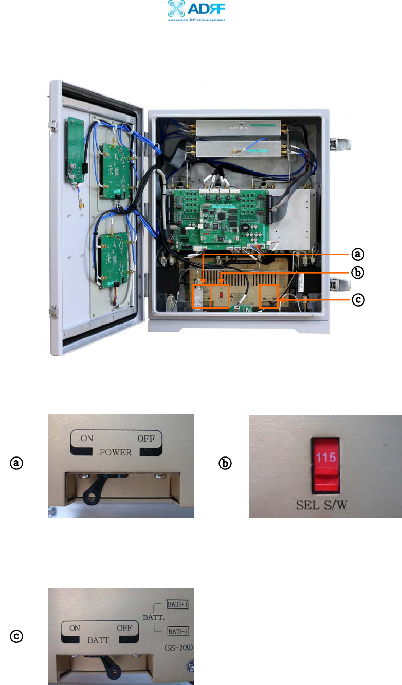
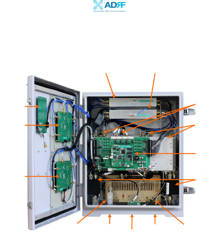
- Selector switch
See installation instructions before connecting to the supply
Fi
g
ure 4: AEON-9030 Inside View
Fi
g
ure 5: AC Power Switch Fi
g
ure 6: 110/200V Select Switch
Fi
g
ure 7: Batter
y
Selec
t
Switch
AEON-9030 RF Repeater
User Manual V1.0
Advanced RF Technologies, Inc. Proprietary Document Page 11 of 51
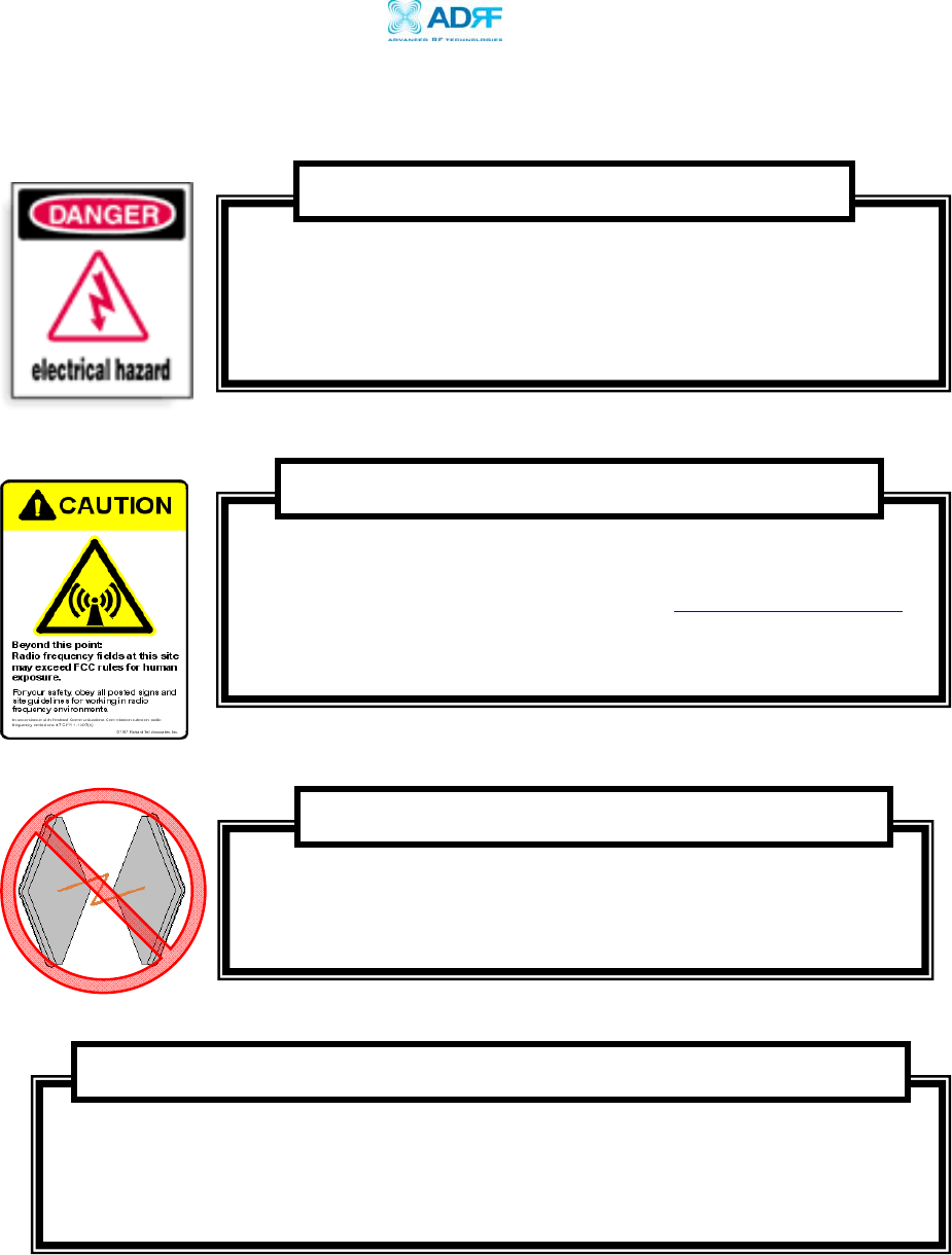
1.2 Warnings and Hazards
Actual separation distance is determined upon gain of antenna used.
Please maintain a minimum safe distance of at least 50 cm while operating near the
donor and the server antennas. Also, the donor antenna needs to be mounted
outdoors on a permanent structure.
RF EXPOSURE & ANTENNA PLACEMENT Guidelines
Operating the AEON-9030 with antennas in very close proximity
facing each other could lead to severe damage to the repeater.
WARNING! DAMAGE TO REPEATER
Working with the repeater while in operation, may expose the
technician to RF electromagnetic fields that exceed FCC rules for
human exposure. Visit the FCC website at www.fcc.gov/oet/rfsafety
to learn more about the effects of exposure to RF electromagnetic
fields.
WARNING! EXPOSURE TO RF
Opening the AEON-9030 could result in electric shock and may
cause severe injury.
WARNING! ELECTRIC SHOCK
AEON-9030 RF Repeater
User Manual V1.0
Advanced RF Technologies, Inc. Proprietary Document Page 12 of 51
NOTE: This equipment has been tested and found to comply with the limits for a
Class A digital device, pursuant to part 15 of the FCC Rules. These limits are
designed to provide reasonable protection against harmful interference when the
equipment is operated in a commercial environment. This equipment generates,
uses, and can radiate radio frequency energy and, if not installed and used in
accordance with the instruction manual, may cause harmful interference to radio
communications. Operation of this equipment in a residential area is likely to
cause harmful interference in which case the user will be required to correct the
interference at their own expense.
FCC Part 15 Class A
Lithium Battery: CAUTION. REPLACEMENT OF BATTERY WITH THE INCORRECT TYPE
MAY LEAD TO A RISK OF EXPLOSION. DISPOSE OF USED BATTERIES ACCORDING TO
INSTRUCTIONS.
Ethernet Instructions: This equipment is for indoor use only. All cabling should be
limited to inside the building.
Opening or tampering the AEON-9030 will void all warranties.
WARRANTY
AEON-9030 RF Repeater
User Manual V1.0
Advanced RF Technologies, Inc. Proprietary Document Page 13 of 51
2. AEON-9030 Overview
2.1 Switches & Indicators
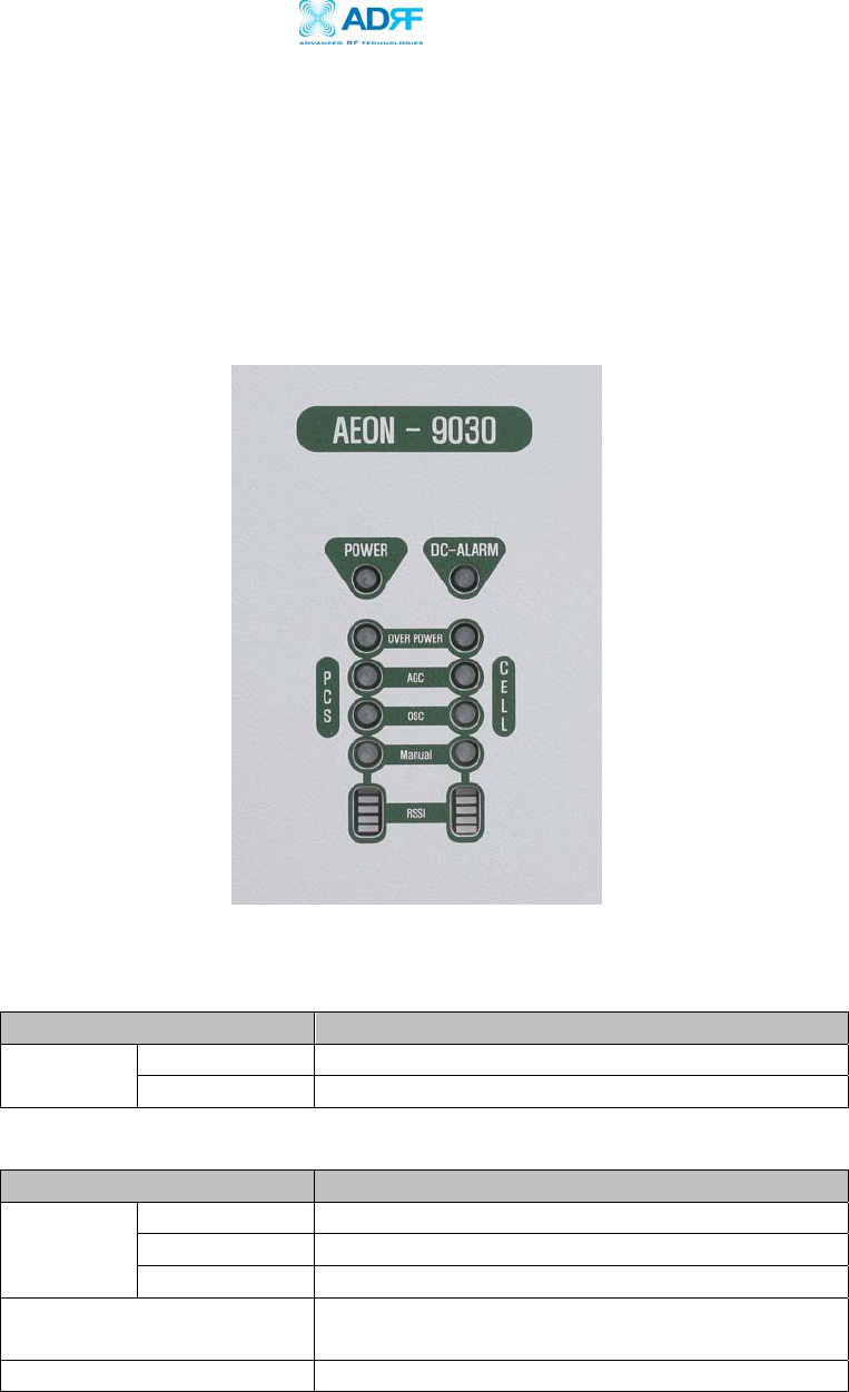
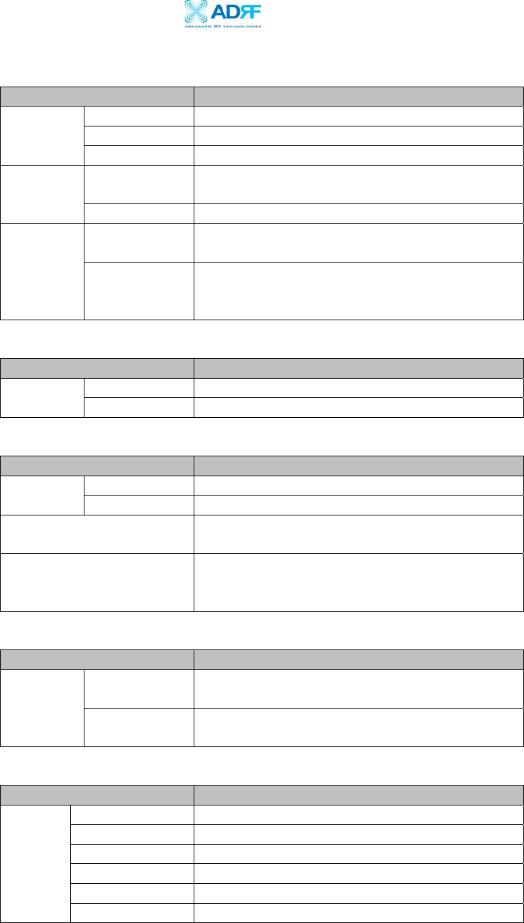
2.1.1 LEDs
The AEON-9030 has ten LEDs on the front panel of the repeater as shown
below in Figure 8.
POWER LED
Parameters Specifications
LED Repeater On Green LED on
Repeater Off Green LED off
DC-ALARM LED
Parameters Specifications
LED Normal LED off
Soft fail Green LED on
Hard fail Red LED on
Condition for Alarm
Activation Current > 9A (Hard Fail)
Current < 2A (Soft Fail)
After Alarm Activation Full Spectrum (PCS/Cellular) shutdown
Figure 8: AEON-9030 Repeater LED View
AEON-9030 RF Repeater
User Manual V1.0
Advanced RF Technologies, Inc. Proprietary Document Page 14 of 51
OVER POWER LED
Parameters Specifications
LED Normal LED off
Soft fail PCS/ Cellular Green LED on
Hard fail PCS/ Cellular Red LED on
Condition
for Alarm
Activation
Soft fail Max power +1 <measured output < max
power+2
Hard fail measured output > max power + 2
Following
Alarm
Activation
Soft fail Only the alarm is activated and the repeater
operates as normal
Hard fail The function associated with the alarm shuts
down, and the shutdown process goes into
effect
AGC LED
Parameters Specifications
LED AGC On PCS / Cellular Green LED On
AGC Off PCS / Cellular LED Off
OSC LED
Parameters Specifications
LED Normal LED off
Hard fail Red LED on
Condition for Alarm
Activation Repeater goes into oscillation
Following Alarm
Activation
The portion associated with the oscillation
shuts down, and at time of oscillation the
defined procedure goes into effect
MANUAL LED
Parameters Specifications
LED
Manually
HPA Off/On PCS / Cellular Green LED On
Factory set or
Reboot PCS / Cellular Green LED Off
RSSI LED BAR
Parameters Specifications
LED
Input < -75dBm PCS / Cellular All LED Off
Input < -65dBm PCS / Cellular one LED On
Input < -55dBm PCS / Cellular two LED On
Input < -45dBm PCS / Cellular three LED On
Input < -35dBm PCS / Cellular four LED On
Input > -25dBm PCS / Cellular five LED On
AEON-9030 RF Repeater
User Manual V1.0
Advanced RF Technologies, Inc. Proprietary Document Page 15 of 51
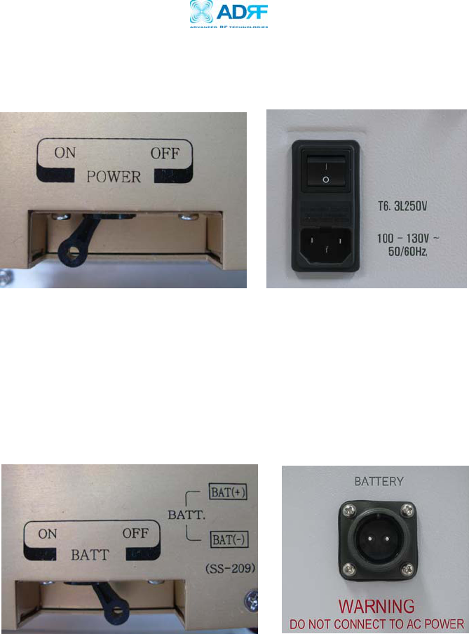
2.1.2 AC Power Switch
The AC Power on/off switch is located on the inside and bottom of repeater
(Figure 9). The switch should be powered on after the repeater has been
installed properly.
2.1.3 Back Up Battery Switch & Battery Port
The Battery Switch can be used to provide power to the optional External
Backup Battery.
If a backup battery is utilized, please connect the battery to the unit via the
external battery port as shown in Figure 10.
(WARINING: If the Circuit Protector Switch is not turned OFF there may be a risk of
damage or electric shock)
Note: Please contact ADRF Technical Support for assistance if you are unfamiliar with the
installation procedure of our battery box.
Fi
g
ure 9: AC Power Switch
Fi
g
ure 10: Batter
y
Switch & Batter
y
Po
r
t

AEON-9030 RF Repeater
User Manual V1.0
Advanced RF Technologies, Inc. Proprietary Document Page 16 of 51
2.1.4 Ethernet Port
Figure 11 shows the Ethernet port which is used to interface with the unit via
RJ-45 crossover cable. Verify that the Host/Remote switch is set to Host and
set your network adapter to “Obtain an IP Address Automatically” and the
repeater will assign an IP Address via DHCP. The Host/Remote switch
should only be set to Remote when an external modem box is being used to
monitor the unit.
Figure 11: Ethernet Port
2.1.5 Modem Module
Figure 12 shows the Modem Module that is used to remotely interface with
the unit via modem. The modem will allow for remote configuration and
monitoring via SNMP.
Figure 12: Modem Module
2.1.6 Other Ports
- Donor Antenna Port
Port where the Donor Antenna will be connected.
- Sever Antenna Port
Port where the Server Antenna will be connected.

AEON-9030 RF Repeater
User Manual V1.0
Advanced RF Technologies, Inc. Proprietary Document Page 17 of 51
2.2 Installation
2.2.1 Tools
No special tools or equipments are needed to install the AEON-9030.
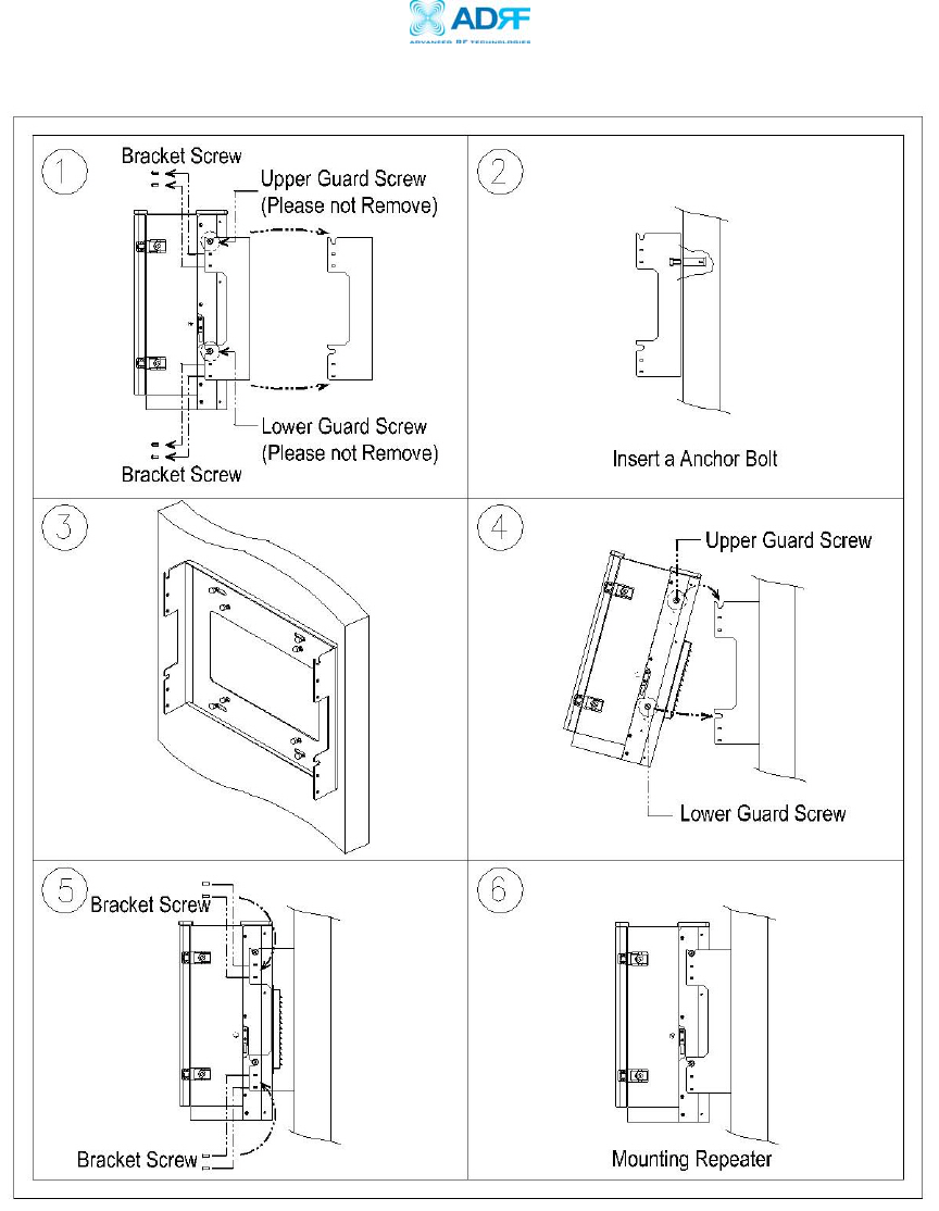
2.2.2 Procedure
The wall-mounting bracket has six mounting holes which are used to mount
the bracket to the wall. The wall bracket must be securely attached to the wall
in order to support the weight of the AEON-9030. After mounting the bracket
to the wall, the AEON-9030 is placed on the mounting bracket using the four
guard screws attached to the AEON-9030.
The following steps should be followed while mounting the repeater:
Installation Procedure
① Take the AEON-9030 out of the box.
② Using the six anchor bolts, mount the bracket on the wall.
③ Make sure the bracket is securely mounted.
④ Slightly tilt the top portion of the repeater and mount the repeater onto the
wall as shown in the picture on page 18. Hook the upper 2 guard screws
first and then slide/push in the lower 2 guard screws into place.
⑤ Make sure the AEON-9030 is securely placed onto the wall bracket.
⑥ Fasten the 8 bracket screws back properly on both sides.
⑦ Verify that the repeater is secure and properly grounded.
AEON-9030 RF Repeater
User Manual V1.0
Advanced RF Technologies, Inc. Proprietary Document Page 18 of 51
Fi
g
ure 13: Re
p
eater Mountin
g
Instructions
AEON-9030 RF Repeater
User Manual V1.0
Advanced RF Technologies, Inc. Proprietary Document Page 19 of 51
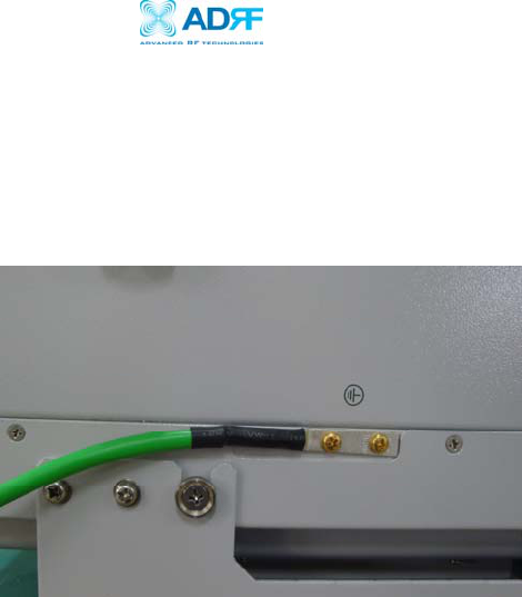
2.2.3 Grounding
A ground cable is included in the packaging and should be properly connected
to the repeater as shown below.
Figure 14: Ground Cable Connection
AEON-9030 RF Repeater
User Manual V1.0
Advanced RF Technologies, Inc. Proprietary Document Page 20 of 51
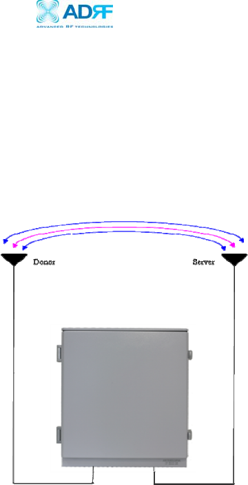
2.3 Antenna Separation/Isolation
Separation between antennas is necessary to prevent oscillation.
Oscillation occurs when the signal entering the system continually re-
enters, due to the lack of separation between the donor and server antenna.
This creates a constant amplification of the same signal. As a result, the
noise level rises above the signal level.
To prevent feedback, the donor and server antenna must be separated by
an appropriate distance to provide sufficient isolation. Isolation is attained
by creating sufficient distance between the donor and nearest server
antenna so that the output of one antenna does not reach the input of the
other. This distance is determined by the gain of the repeater.
A sufficient isolation value is 13 ~ 15 dB greater than the maximum gain
of the repeater. The AEON-9030 has a maximum gain of 90 dB, thus it
requires an isolation of at least 103 ~ 105 dB.
Figure 15: RF Repeater Oscillation
AEON-9030 RF Repeater
User Manual V1.0
Advanced RF Technologies, Inc. Proprietary Document Page 21 of 51
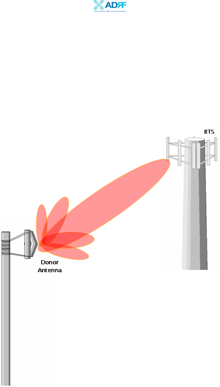
2.4 Line of Sight
The donor antenna which points toward the base station typically has a
narrow beam antenna pattern. As a result, a slight deviation away from
the direction of the BTS can lead to less than optimum results. In addition,
obstacles between the repeater and the BTS may impair the repeater from
obtaining any BTS signal. As a result, the repeater cannot transmit signal
to the coverage area. Therefore, a direct line of sight to the BTS for the
donor antenna is vital to the function of a repeater. For the same reason,
placing the server antenna in direct line of sight of the coverage area is
also necessary.
Figure 16: Direct Line of Sight to the BTS
AEON-9030 RF Repeater
User Manual V1.0
Advanced RF Technologies, Inc. Proprietary Document Page 22 of 51
3. AEON-9030 AROMS Setup
3.1 Repeater/PC Connection Using AROMS
i) Wait until the Power LED is lit in green. Connect the LAN cable between the
laptop’s Ethernet port and the repeater’s Ethernet port.
Note: Under Local Area Connection in Network Settings, make sure to select
Obtain an IP address automatically under Internet Protocol (TCP/IP) properties.
** Before proceeding to the next step, please close the cabinet door (do
not lock) at this time in order to avoid inadvertent RF feedback going
inside the repeater.”
ii) Launch Microsoft Internet Explorer
Note: ADRF’s Web GUI has not been tested for compatibility with any other web
browsers (e.g. Netscape, Mozilla, etc.).
iii) Please type the following IP address into the address bar of MS Internet
Explorer:
http://192.168.63.1/home.asp
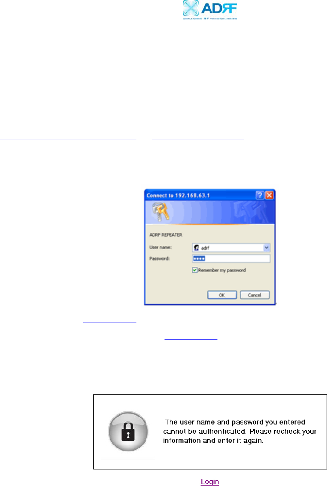
iv) The following login screen will appear:
AEON-9030 RF Repeater
User Manual V1.0
Advanced RF Technologies, Inc. Proprietary Document Page 23 of 51
If you are not the Super-User, please type in your assigned username & password
which you should have received from the Super-User.
The default username and password for the General User is adrf & adrf,
respectively.
If the username & password is typed in incorrectly, the following screen will
appear:
** If you cannot connect to the Web GUI, Please see the LAN Connectivity
Troubleshooting Guide on Page 38 or visit
http://www.adrftech.com/wiki/index.php?n=Connectivity.ConnectingViaLAN
AEON-9030 RF Repeater
User Manual V1.0
Advanced RF Technologies, Inc. Proprietary Document Page 24 of 51
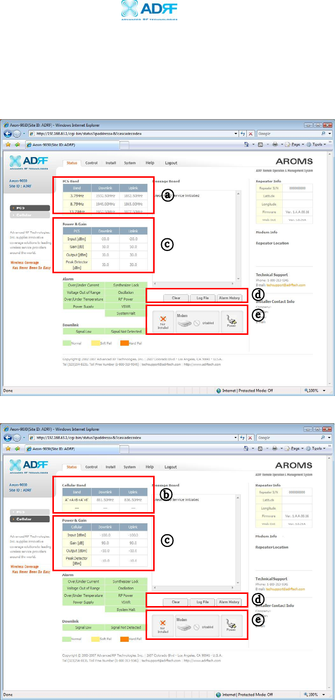
3.2 Repeater Status
PCS Repeater Status
If you click on Status tab, the following window will appear:
Cellular Repeater Status
AEON-9030 RF Repeater
User Manual V1.0
Advanced RF Technologies, Inc. Proprietary Document Page 25 of 51
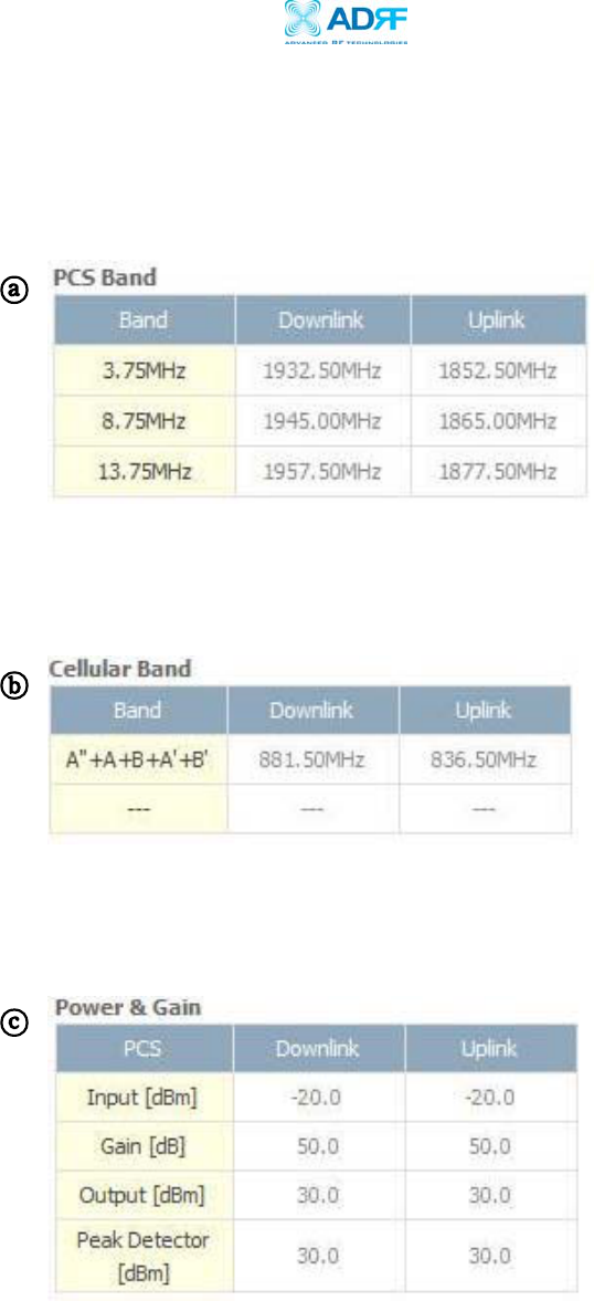
In this window, the user can view the following:
(To change any parameters, e.g., Channel frequency, bandwidth, Gain
Settings, AGC Level, etc., you must go to the Install or the Control
window.)
- CDMA Band: Will display the center frequencies of the 1900 MHz filtered
BWs on the downlink and uplink respectively.
- Cellular Band: Will display the center frequencies of the 800 MHz filtered BWs
on the downlink and uplink respectively.
- Power & Gain: Will display the repeater’s input, gain and output power on the
downlink and uplink.
AEON-9030 RF Repeater
User Manual V1.0
Advanced RF Technologies, Inc. Proprietary Document Page 26 of 51
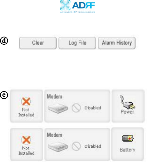
- Clear: Will delete message board contents.
- Log File: Will download repeater’s log file.
- Alarm History: Will provide additional alarm log for repeater’s status.
- Installed icon: Shows the current “Install” status (Installed or Not Installed).
- Modem icon: Shows the current modem status (Disabled, Connected, Not
connected).
- Power icon: Shows the current electric source [AC power, Battery (Shown
when an external battery box is installed)].

AEON-9030 RF Repeater
User Manual V1.0
Advanced RF Technologies, Inc. Proprietary Document Page 27 of 51
- Alarms: The unit will display seven alarms with three different status
conditions (Normal, Soft Fail or Hard Fail).
- Message Board: Displays the 20 most recent log messages (Alarms &
Heartbeats).
- Installation: Displays the repeater’s installation status (Not Installed or
Installed).
- Repeater Info: Displays the repeater’s serial number, and location
information (latitude and longitude coordinates).
- Repeater Location: Displays the address where the repeater is installed
- Technical Support: Displays ADRF’s technical support contact information.
- Installer Contact Info: Displays the installer’s name, phone and e-mail
address.
- Modem (only applicable if a wireless modem is connected to the repeater):
The Auto Connection box needs to be checked when the wireless modem is
installed inside the repeater. A wireless modem is used in order to send the
alarms and the heartbeat over the air to the Wireless Provider’s NOC.
Note: Once successfully logged in, the repeater model name and the site/cascade
ID will be displayed on the top left of all the windows.
AEON-9030 RF Repeater
User Manual V1.0
Advanced RF Technologies, Inc. Proprietary Document Page 28 of 51
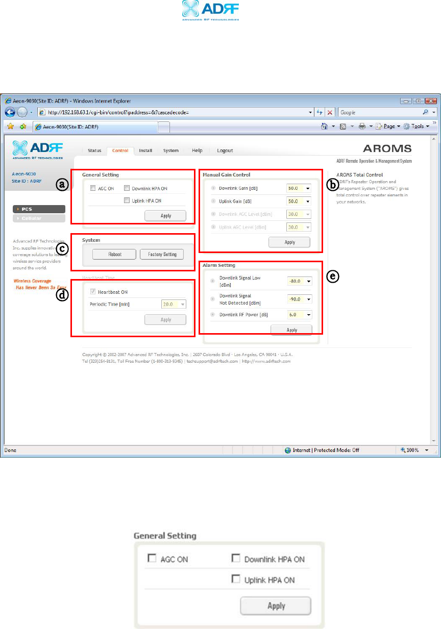
3.3 Repeater Control
If you click on Control tab, the following window will appear:
In this window, the user can adjust the following parameters:
ⓐ General Setting
- Automatic Gain Control (Default mode is Off)
- Downlink HPA on/off (Default mode is Off)
- Uplink HPA on/off (Default mode is Off)
AEON-9030 RF Repeater
User Manual V1.0
Advanced RF Technologies, Inc. Proprietary Document Page 29 of 51
AGC Mode
AGC (Auto Gain Control) adjusts the variable gain of the repeater on both
downlink and uplink to ensure a constant specified output power. The
functionality of the AGC feature is assured under the condition that the input BTS
signal is within the specified AGC range and that sufficient isolation exists
between antennas. By default, the AGC ON box is not checked. To change the
AGC levels on the Uplink and Downlink, AGC ON must be checked.
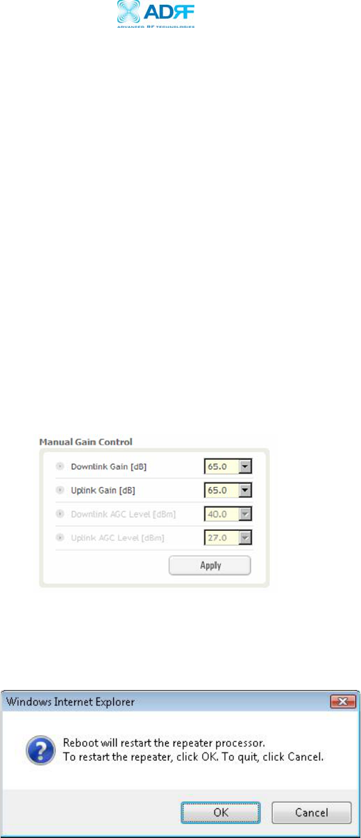
ⓑ Manual Gain Control
- Downlink Gain Control (60 to 90 dB @ 0.5 dB step)
- Uplink Gain Control (60 to 90 dB @ 0.5 dB step)
- Downlink AGC Level
AEON-9030: 10 to 30dBm @ 0.5 dB step, default value: 30dBm
- Uplink AGC Level
AEON-9030: 10 to 30dBm @ 0.5 dB step, default value: 30dBm
ⓒ System
- If you click the Reboot button, the following message box will appear:
When a system reboot is performed, no settings are changed, but coverage is
temporarily lost.
Please wait approximately 30 seconds to 1 minute for the system to reboot.
AEON-9030 RF Repeater
User Manual V1.0
Advanced RF Technologies, Inc. Proprietary Document Page 30 of 51
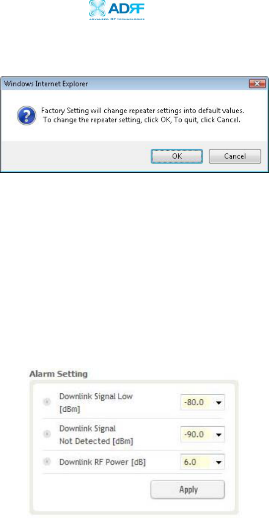
- If you click the Factory Setting button, the following message box will appear:
Factory Setting will erase the saved settings by the user and change all the
parameters to the factory default settings.
ⓓ Heartbeat Time
- Heartbeat is disabled.
ⓔ Alarm Setting
- Downlink Signal Low (-90 ~ -30 dBm @ 0.5 dB step, default value: -80 dBm)
- Downlink Signal Not Detected (-90 ~ -96 dBm @ 0.5 dB step, default value: -90
dBm)
- Downlink RF Power (2 ~ 10 dB @ 0.5 dB step, default value: 6 dB)
AEON-9030 RF Repeater
User Manual V1.0
Advanced RF Technologies, Inc. Proprietary Document Page 31 of 51
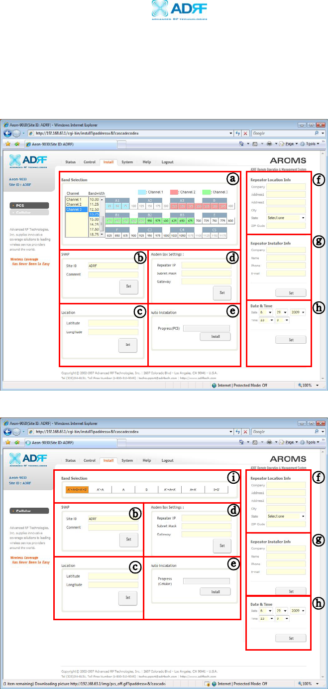
3.4 Repeater Install
If you click on the Install tab, the following window will appear:
PCS Install
Cellular Install
AEON-9030 RF Repeater
User Manual V1.0
Advanced RF Technologies, Inc. Proprietary Document Page 32 of 51
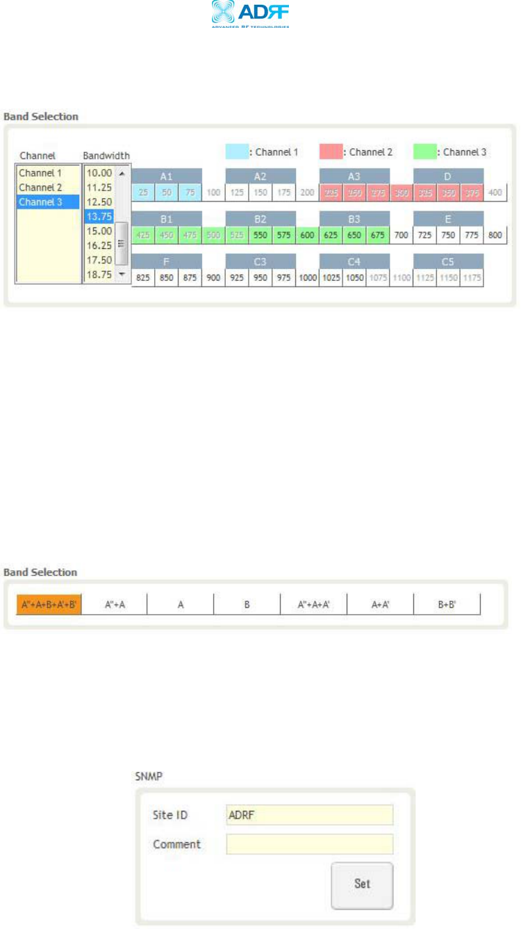
ⓐ PCS Band Selection
- Step 1: Channel Select
- Step 2: Bandwidth Select
- Step 3: FA Select
* 3 Separate Channel Selections are possible.
The AEON-9030 has three independent RF PCS channels: Channel 1, Channel 2
and Channel 3. Each channel supports 1.25 MHz to 18.75MHz bandwidth.
One can use any of the three channels (three contiguous: Unit will not filter 1FA
as guard band nor non-contiguous channels). Therefore, the instantaneous
bandwidths that the AEON-9030 supports is 1.25MHz to 56.25MHz.
Cellular Band Selection
Simply click on the desired operating bandwidth.
ⓑ SNMP
Type in the assigned Site/Cascade ID and Comment.
Default Site ID is ADRF.
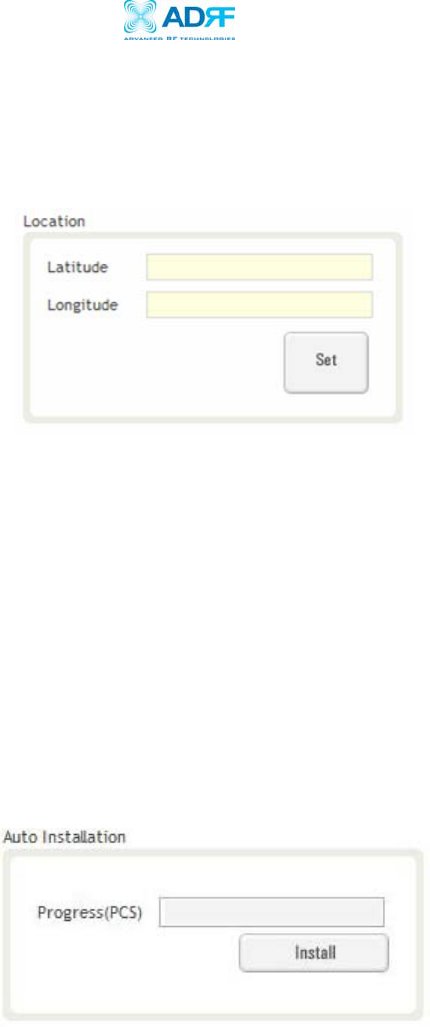
ⓒ Repeater Location
AEON-9030 RF Repeater
User Manual V1.0
Advanced RF Technologies, Inc. Proprietary Document Page 33 of 51
Please type in the coordinates where the repeater is installed.
Ex) Latitude: N/S (Upper Case) 034.123456
Longitude: E/W (Upper Case) 034.123456
ⓓ Modem Box Settings: Will display the Repeater’s Static IP Address, Subnet
Mask, and Gateway. This information is necessary when using the Repeater in
conjunction with an External Modem Box. Default values are:
Repeater IP: 192.168.63.5
Subnet Mask: 255.255.255.0
Gateway: 192.168.63.254
ⓔ Auto Installation
Click the Install button to automatically setup the repeater.
It may take up to 3 minutes to complete the process. You will see a gradual
progress bar display. After the process is completed, a pop-up window will
display a “Installation Successfully Completed” message.
After the Installation Routine is complete, click on the Status tab and the
Installation box should have changed from “Not Installed” to “Installed”.
If the AEON-9030 detects a problem during the installation process, a pop-up
message will appear stating the issue, e.g., “Modem is not detected.” Please
follow the instructions and address the problem to finish the installation process.
If the problem persists, please contact our technical support.
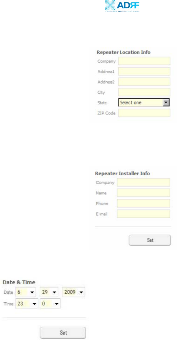
Repeater Location Info
AEON-9030 RF Repeater
User Manual V1.0
Advanced RF Technologies, Inc. Proprietary Document Page 34 of 51
Please type in the physical address where the repeater is installed.
ⓖ Repeater Installer Info
Please type in the installer’s: company, name, phone number and e-mail address
for technical support.
ⓗ Date and Time: Sets the date and time for the internal clock (required for Log
Messages)
AEON-9030 RF Repeater
User Manual V1.0
Advanced RF Technologies, Inc. Proprietary Document Page 35 of 51
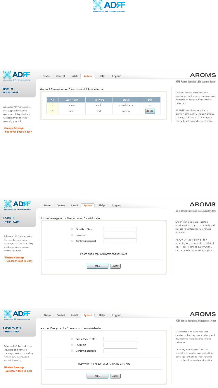
3.5 Repeater System
If you click on the Account menu under the System tab, the following window
will appear:
Note: If you are the Super-User, you will see account management section under
the System Window. If you are a general user, you will not be able to see the
account management portion.
Only the Super-User can add, delete and modify a user. The following window
illustrates how a new user can be added by simply clicking on New Account.
The following window illustrates how an administrator can be changed or
removed by simply clicking on Administrator.
AEON-9030 RF Repeater
User Manual V1.0
Advanced RF Technologies, Inc. Proprietary Document Page 36 of 51
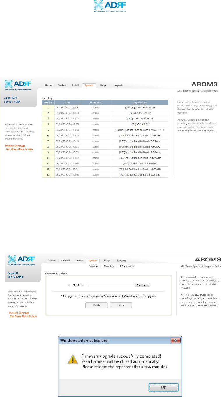
User Log
If you click on the User Log menu under the System tab, the following window
will appear. The following window displays the changes made to the Repeater
settings.
Firmware Update
If you click on Firmware Upgrade, the following window will appear. You can
browse through your PC and locate the firmware file. Once it’s selected, click on
Update and it will upload the firmware automatically and close the session. You
will need to re-login again after the firmware update is performed. This will cause
a temporary loss in coverage.

AEON-9030 RF Repeater
User Manual V1.0
Advanced RF Technologies, Inc. Proprietary Document Page 37 of 51
4. Maintenance Guide for AEON-9030
4.1 Periodic Inspection Checklist
4.1.1 Check for loose connections to the repeater and antennas. If connections
are loose, make sure that all connections are tightly fastened.
4.1.2 Check that cables and connectors are in good condition.
4.1.3 Ensure that the repeater brackets are in good condition and that the
repeater is securely fastened.
4.2 Preventive Measures for Optimal Operation
4.2.1 Recommendations
Perform the Periodic Inspection Checklist quarterly or semi-annually.
4.2.2 Precautions
Do not operate the repeater with the antennas in extremely close proximity
as this may cause damage to the repeater.
Do not change parameters unless instructed to do so by an authorized
supervisor.
Do not move the repeater unless instructed to do so by an authorized
supervisor.
Do not detach any cables to the repeater unless repair of respective
components are necessary.

AEON-9030 RF Repeater
User Manual V1.0
Advanced RF Technologies, Inc. Proprietary Document Page 38 of 51
5. AEON-9030 Troubleshooting Guide
5.1 Connectivity Guide for LAN
If you are unable to connect to the Web GUI, please follow the steps listed below:
i) If you see the icon below (Figure 17)
Figure 17
- Check the Power Line to see whether or not the repeater is being powered correctly.
- Use the Cross-over Cable that came with the repeater to connect the repeater to your
laptop. If you still cannot connect, replace the cross-over cable with another one.
- If unsuccessful, power the repeater down and wait for at least 5-10 seconds for it to
electrically discharge, then power the repeater back up. Wait for the PWR LED to light
up before attempting the IP address in browser again. (When the repeater powers up,
you will hear a faint click)
ii) If you see the icon in Figure 18, then the computer is in the process of
obtaining an IP Address and you will not be able to connect to the unit. Once you see the
icon in Figure 19 then you can attempt to connect to the unit.
Figure 18
Figure 19
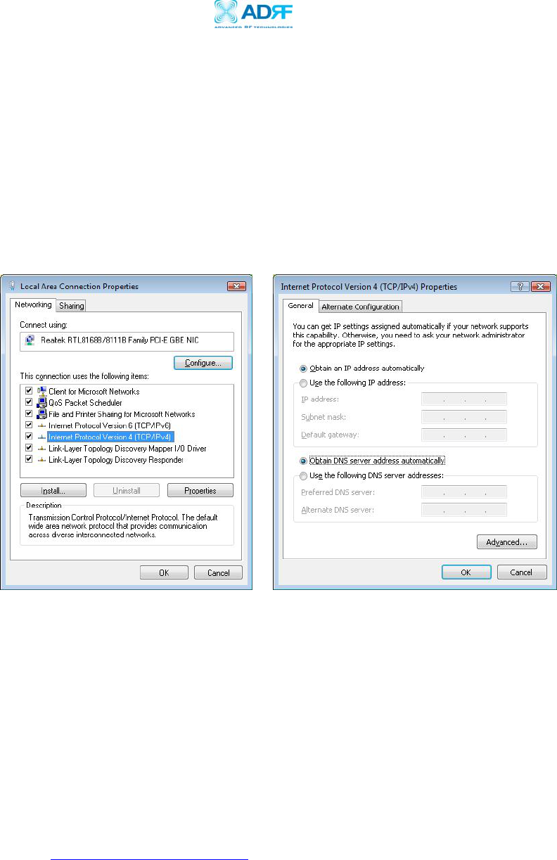
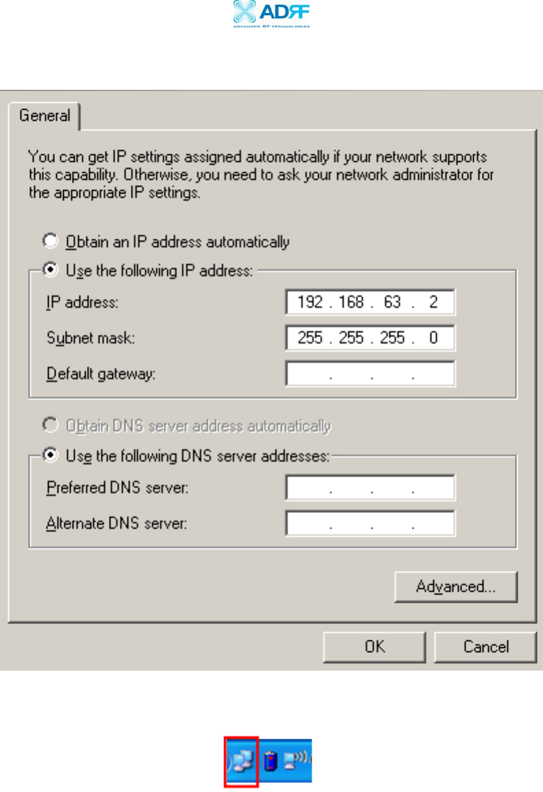
- If unsuccessful: Go to Start Control Panel or Start Settings Control Panel.
Double-Click Network Connections Right-Click Local Area Connection Left-Click
Properties Scroll down to the bottom of the list Double-Click Internet Protocol
(TCP/IP)
Instead of “Obtain an IP address automatically”, please select “Use the following IP
address” and input the same values as shown in Figure.
AEON-9030 RF Repeater
User Manual V1.0
Advanced RF Technologies, Inc. Proprietary Document Page 39 of 51
iii) If you see the icon in Figure 20, then the IP Address has been obtained. If you
see this icon and still cannot connect to the unit, then please follow the steps listed below.
Figure 20
Verify HOST/REMOTE switch is set to the HOST mode.
- When the unit is set to Host Mode, the IP address for the unit is 192.168.63.1
- When the unit is set to Remote Mode, the IP address for the unit is 192.168.63.5
Please note the only time ‘REMOTE’ mode is utilized is for modem box monitoring.
AEON-9030 RF Repeater
User Manual V1.0
Advanced RF Technologies, Inc. Proprietary Document Page 40 of 51
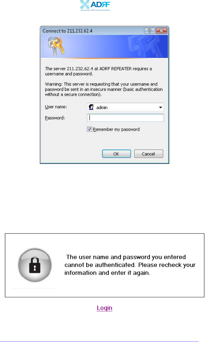
iv) Use Microsoft Internet Explorer to log into the Web-GUI
Note: ADRF’s Web GUI is not compatible with other web browsers such as Netscape,
Mozilla’s Firefox, Opera, etc.
Please type the following IP address into the address bar of MS Internet Explorer:
http://192.168.63.1/home.asp or http://192.168.63.1/
The following login screen will appear:
If you are not the Super-User, please type in your assigned username & password which
you should have received from the Super-User. The default username and password for
the General User is adrf & adrf, respectively.
If the username & password is typed in incorrectly, the following screen will appear:
v) If the steps above do not remedy the situation and you still cannot connect to
the Web-GUI, please contact ADRF Tech Support (800-313-9345).

AEON-9030 RF Repeater
User Manual V1.0
Advanced RF Technologies, Inc. Proprietary Document Page 41 of 51
5.2 Troubleshooting Guide for Repeater
Alarm Status Parameter Troubleshooting
VSWR Hard Fail VSWR Over 3:1
1. Make sure connectors are tight at each port.
Sweep lines.
2. Use a 50 Ω dummy load, connect it to the
Alarming Port to check whether the repeater
is faulty. (e.g. if the Down Link is alarming,
connect the dummy to the Server Port.)
3. If multiple Server Antennas are connected,
connect only one antenna and recheck the
Alarm. If the Alarm clears, faulty connectors
like combiners/ splitters in the serving line and
lightning arrestors (polyphasers) may be
causing the problem.
Over Power
Soft Fail UL/DL 31dBm~32dBm >Max Output
Power+1dB 1. Check Input/Gain/Output values in the
‘Status Page’
2. Check Input Level (If the input exceeds the
max rated power, add an Attenuator to the
input/ Donor port)
3. Check whether AGC is On (In the case of UL
Shutdown, make sure that Tracking is OFF)
4. Factory Setting & Reboot
Hard Fail UL/DL Output Power +33dBm > Max Output
Power +3dB
RF Power Soft Fail Invalid Output Level of Gain
1. Check whether Input/Gain/Output are
invalid.
2. From the Control page, check the Alarm
Settings.
AEON-9030 RF Repeater
User Manual V1.0
Advanced RF Technologies, Inc. Proprietary Document Page 42 of 51
(Default 6dB)
3. Go under ‘Control’ tab and turn off AGC and
change gain manually to verify BDA is
responding to changes. Recheck the measured
values.
Signal Low Soft Fail Downlink Input Value is less than threshold:
PCS / Cell: -80dBm minimum
1. Ensure proper ports are connected (Donor/
Server).
2. Verify the Donor antenna is pointed toward
the correct cell site.
3. Verify the selected band(s) and be sure it is
the right band(s) for the area.
4. Please be aware that our BDA typically
require well above -85dBm (threshold) of
incoming RSSI on the DL side.
Under/Over
Current Soft Fail Current falls out of the permitted range 1. Factory Setting & Reboot
2. Recheck, if continues, contact Tech Support.
Hard Fail
Over
Temperature Soft Fail Repeater’s internal temperature exceeds the permitted range 1. Factory Setting & Reboot
2. Recheck, if continues, contact Tech Support.
Hard Fail
Input Overload Hard Fail Input Signal Level increases beyond the set range:
PCS/ Cell: -30dBm max input
1. Add attenuator to donor/server antenna
(Applicable to DAS)
2. Factory Setting & Reboot
Low Isolation
Oscillation Antennas are located too close to one another, causing RF output to feed
input.
1. Check Input Level. (fluctuates drastically)
2. We recommend 13~15dB + max gain of
repeater between the donor and the server
antenna as an isolation value.
3. Check antenna direction (make sure that the
Donor and Server antennas are not facing
one another)
4. Placing an attenuator before the nearest
serving antenna can also help to increase
isolation.

AEON-9030 RF Repeater
User Manual V1.0
Advanced RF Technologies, Inc. Proprietary Document Page 43 of 51
Connectivity Issue Unable to Interface to repeater with GUI Software.
1. Please verify under ‘Device Manager’ of
Windows that the necessary drivers for the USB
to serial adapter are installed.
2. Be sure to use the GUI software from the CD
that came with the repeater.
3. If for some reason the CD is not available,
contact 24HR tech support to acquire the
appropriate one.
4. In the event of using a USB-to-serial
converter, you must be sure to the ‘COM port’
number on the ‘STATUS PAGE’ matches the
COM port number of the USB to- serial
adapter in your ‘Device Manager’ of
Windows.
5. If the GUI software at any time reports a
missing file error such as “component
missing”, please be sure to contact our tech
support staff directly at the number provided
below.
6. Connectivity is accomplished successfully
when both TX/RX lights are blinking green
in the lower right-hand corner of the GUI
software.
Connecting to DAS
All our PCS as well as Cellular BDAs can have the ‘AGC’ function enabled
and the ‘Downlink AGC Level’ set from 0dBm to whichever value is
specified by the manufacturer for common DAS applications.
PCS: lowest DL AGC value 0dBm
To get output power on the Downlink side of
the BDA even lower to plug into a DAS system,
the use of 5dB or 10dB attenuators/pads with
the proper tolerance of wattage is
recommended.
For any other issues, contact ADRF Tech Support at 1-800-313-9345 or 1-323-514-9070

AEON-9030 RF Repeater
User Manual V1.0
Advanced RF Technologies, Inc. Proprietary Document Page 44 of 51
6. Warranty and Repair Policy
6.1 General Warranty
The AEON-9030 carries a Standard Warranty period of three (3) years unless indicated
otherwise on the package or in the acknowledgment of the purchase order.
6.2 Limitations of Warranty
Your exclusive remedy for any defective product is limited to the repair or replacement of
the defective product. Advanced RF Technologies, Inc. may elect which remedy or
combination of remedies to provide in its sole discretion. Advanced RF Technologies,
Inc. shall have a reasonable time after determining that a defective product exists to
repair or replace the problem unit. Advanced RF Technologies, Inc. warranty applies to
repaired or replaced products for the balance of the applicable period of the original
warranty or ninety days from the date of shipment of a repaired or replaced product,
whichever is longer.
6.3 Limitation of Damages
The liability for any defective product shall in no event exceed the purchase price for the
defective product.
6.4 No Consequential Damages
Advanced RF Technologies, Inc. has no liability for general, consequential, incidental or
special damages.
6.5 Additional Limitation on Warranty
Advanced RF Technologies, Inc. standard warranty does not cover products which have
been received improperly packaged, altered, or physically damaged. For example,
broken warranty seal, labels exhibiting tampering, physically abused enclosure, broken
pins on connectors, any modifications made without Advanced RF Technologies, Inc.
authorization, will void all warranty.
6.6 Return Material Authorization (RMA)
No product may be returned directly to Advanced RF Technologies, Inc. without first
getting an approval from Advanced RF Technologies, Inc. If it is determined that the
product may be defective, you will be given an RMA number and instructions in how to
return the product. An unauthorized return, i.e., one for which an RMA number has not
been issued, will be returned to you at your expense. Authorized returns are to be
shipped to the address on the RMA in an approved shipping container. You will be given
our courier information. It is suggested that the original box and packaging materials
should be kept if an occasion arises where a defective product needs to be shipped back
to Advanced RF Technologies, Inc. To request an RMA, please call (800) 313-9345 or
send an email to techsupport@adrftech.com.

AEON-9030 RF Repeater
User Manual V1.0
Advanced RF Technologies, Inc. Proprietary Document Page 45 of 51
Appendix A: Specifications
A.1 Electrical Specifications
Parameters Specification Comments
*Frequency
Bands
Cellular Down Link 869 - 894MHz
Up Link 824 - 849MHz
PCS Down Link 1930MHz ~ 1990MHz
Up Link 1850MHz ~ 1910MHz
Max RF output power Down Link (Max) 30dBm / 3FA
Up Link (Max) 30dBm / 3FA
Cellular Sub Bands A”+A+B+A’+B’, A”+A, A+A’, B+B’, A, B,
A+A”+ A’ Selectable blocks of 10, 12.5 and
25 MHz
Max 7
combinations
(*1)
PCS Band Select Feature 1~ 3 selectable bands Selectable in blocks of
1.25~18.75 MHz 1FA=1.25MHz
Max RF input power Down Link -60dBm/Typ, -30dBm/Max
Up Link (Max) -60dBm/Typ, -30dBm/Max
Gain Adjustable Range 30dB(0.5dB/Step)
Noise Figure(Reverse) 5.5dB @max gain
System Delay 5.5 ㎲ (max)
Input VSWR 1.5 : 1 (max)
Rho 12.5% (max at 16/64 QAM)
Gain 90dB (max)
Passband Ripple ±1.5dB
Filter Out of
Band
Attenuation
Cellular > -35dBc @±0.5MHz >-60dBc @±1MHz
PCS > -60dBc @±1MHz
Freq Error Cellular ± 300 Hz
PCS ± 150 Hz
AEON-9030 RF Repeater
User Manual V1.0
Advanced RF Technologies, Inc. Proprietary Document Page 46 of 51
(*1) Cellular Sub Bands
1 BAND Selection 1 25MHz FULL (869~894MHz) Full band
2 869~880MHz A”+A
3 870~880MHz A
4 880~890MHz B
2 BAND Selection 1 869~880MHz, 890~891.5MHz A”+A, A’
2 870~880MHz, 890~891.5MHz A, A’
3 880~890MHz, 891.5~894MHz B, B’
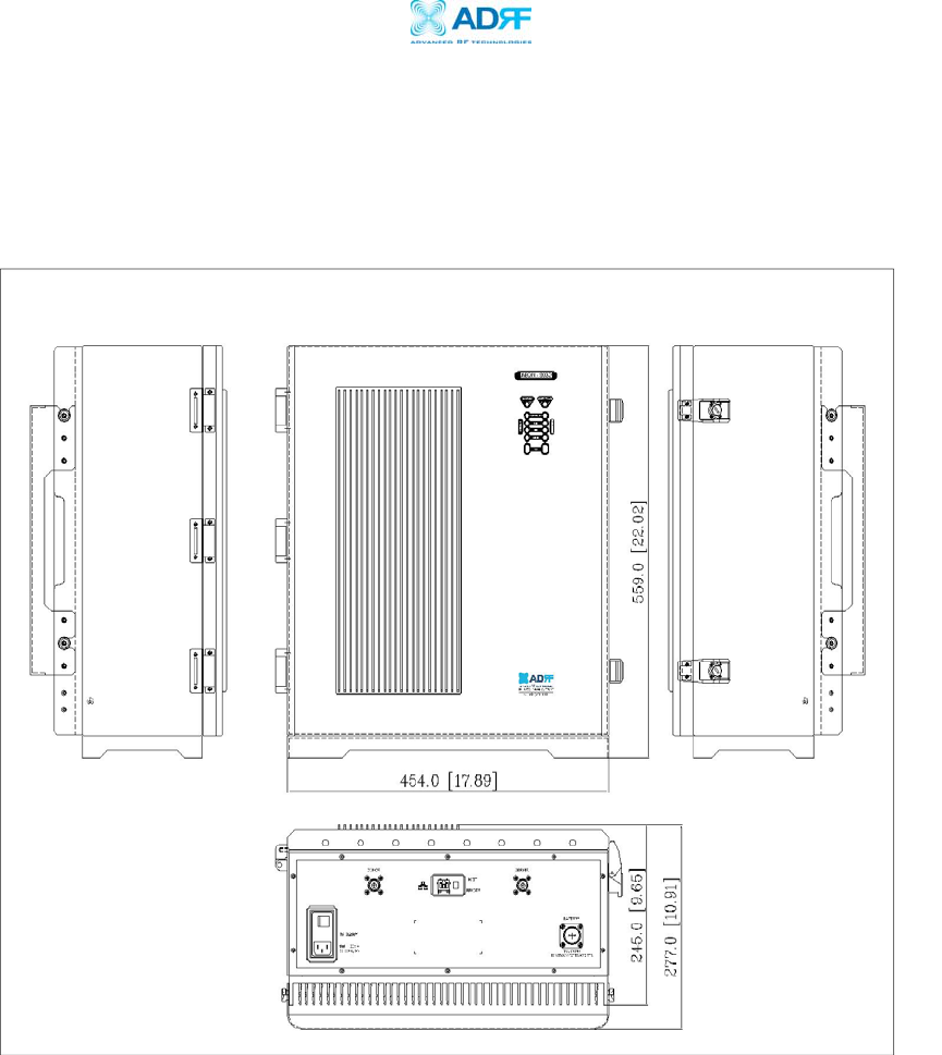
A.2 Mechanical Drawing
Parameters Specifications Comments
Dimension 22” X 17.9.” X 9.65” Inches W x H x D
Bracket excluded
Weight 80.5lbs Bracket excluded
RF Ports N-Type (F) Donor & Server Antenna
Ports
Local Interface RJ45 (DHCP)
Cooling AIR Type
NEMA NEMA 4, IP56 Outdoor Type
A.3 Power Specifications
Parameters Specifications Comments
AC Power 100 ~ 130V / 200 ~ 240V AC Select Switch Type
AC Frequency 50 ~ 60 Hz
AC Supply Protection Fuse
Power Consumption 350 W
Ground External Threaded Stud
A.4 Environmental Specifications
Parameters Specifications Comments
Operating Temperature -5 ~ +50 ℃ Ambient
Relative Humidity 5 ~ 95 %, (Non-Condensing)
Dust Industrial Dust Per Telcordia
GR63 Core
AEON-9030 RF Repeater
User Manual V1.0
Advanced RF Technologies, Inc. Proprietary Document Page 47 of 51
Over voltage category Over voltage category II
Pollution degree Pollution degree 2
A.5 Other Specifications
Parameters Specifications Comments
MTBF > 100,000 Hours
Certificates UL 60950, FCC Part 15, 24
Warranty 3 Years
AEON-9030 RF Repeater
User Manual V1.0
Advanced RF Technologies, Inc. Proprietary Document Page 48 of 51
Appendix B: Mechanical Drawing
AEON-9030
AEON-9030 RF Repeater
User Manual V1.0
Advanced RF Technologies, Inc. Proprietary Document Page 49 of 51
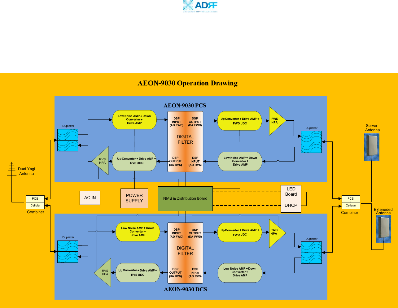
Appendix C: AEON-9030 Overview
C.1 Black Diagram
AEON-9030 RF Repeater
User Manual V1.0
Advanced RF Technologies, Inc. Proprietary Document Page 50 of 51
C.2 Components
AEON-9030
Power Supply
Provides DC power to each module within the repeater.
Controller
Responsible for monitoring the status of each module and controls the parameters.
Also interfaces with PC through Ethernet port.
Donor Antenna Port
Connect Donor Antenna.
Sever Antenna Port
Connect Sever Antenna.
AEON-9030 Internal Components
Cellular FWD/RVS
UP/Down Converte
r
PCS FWD/RVS
UP/Down Converte
r
Donor Port Server Port
Control Board
Ethernet Port Power Supply
Combine
r
Cellular Digital Filte
r
PCS Digital Filter
LED Board
PCS FWD/RVS
HPA, Duplexer
Cellular FWD/RVS
HPA, Duplexer
Modem Coupler

AEON-9030 RF Repeater
User Manual V1.0
Advanced RF Technologies, Inc. Proprietary Document Page 51 of 51
PCS Down Converter Module
The PCS downlink RF signal that enters through the cavity filter is converted to
IF frequency, which is later, converted back to RF frequency through digital
filtering.
PCS Up Converter Module
The PCS uplink RF signal that enters through the cavity filter is converted to IF
frequency, which is later, converted back to RF frequency through digital filtering.
Cellular Down Converter Module
The Cellular downlink RF signal that enters through the cavity filter is converted
to IF frequency, which is later, converted back to RF frequency through digital
filtering.
Cellular Up Converter Module
The PCS uplink RF signal that enters through the cavity filter is converted to IF
frequency, which is later, converted back to RF frequency through digital filtering.
Digital Filter
DSP (Digital Signal Processing) technology is utilized to achieve the highest level
of performance and filtering agility.
Duplexer
Consists of four BPFs (band-pass filters): PCS TX (1930 ~ 1990 MHz) & RX
(1850 ~ 1910 MHz), Cellular TX (869 ~ 894 MHz) & RX (824 ~ 849 MHz)
HPA
Receives the output signal from the PCS, Cellular Up / Down converter module
and amplifies the signal up to the repeater’s maximum rated power level.
LED Board
LED Board displays the state of the repeater. The detailed alarm information can
be viewed via the Web GUI.
PCS, Cellular Digital Filter
The Digital Filter is IF frequency converted back to RF frequency through digital
filtering.
Combiner
Combines Cellular and PCS signals. It consists of three BPFs (band-pass filters):
PCS and Cellular TX and RX.
Modem Module
Contains the CDMA 2000 modem (Kyocera M200).