Advanced RF Technologies AXM700 RF Repeater (Bi-Directional Amplifier) User Manual
Advanced RF Technologies, Inc. RF Repeater (Bi-Directional Amplifier)
UserManual.wiki
>
Advanced RF Technologies
>
AXM700 User Manual
Users Manual
Navigation menu
Upload a User Manual
Namespaces
Wiki Guide
HTML
PDF
Info
Views
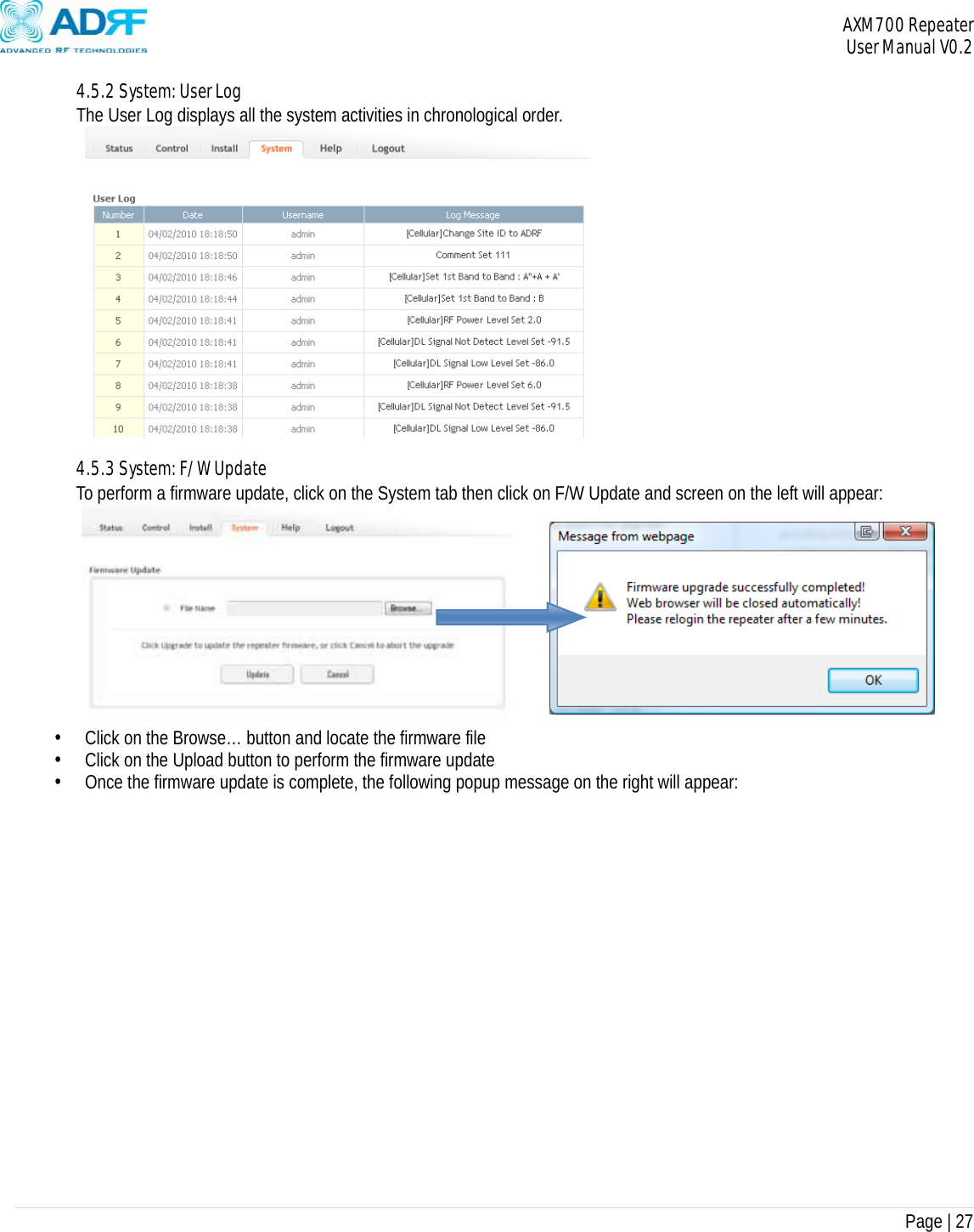
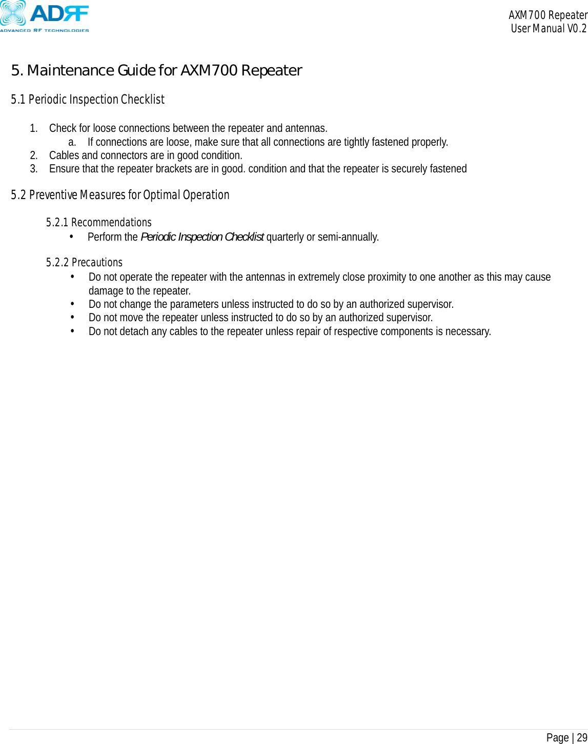
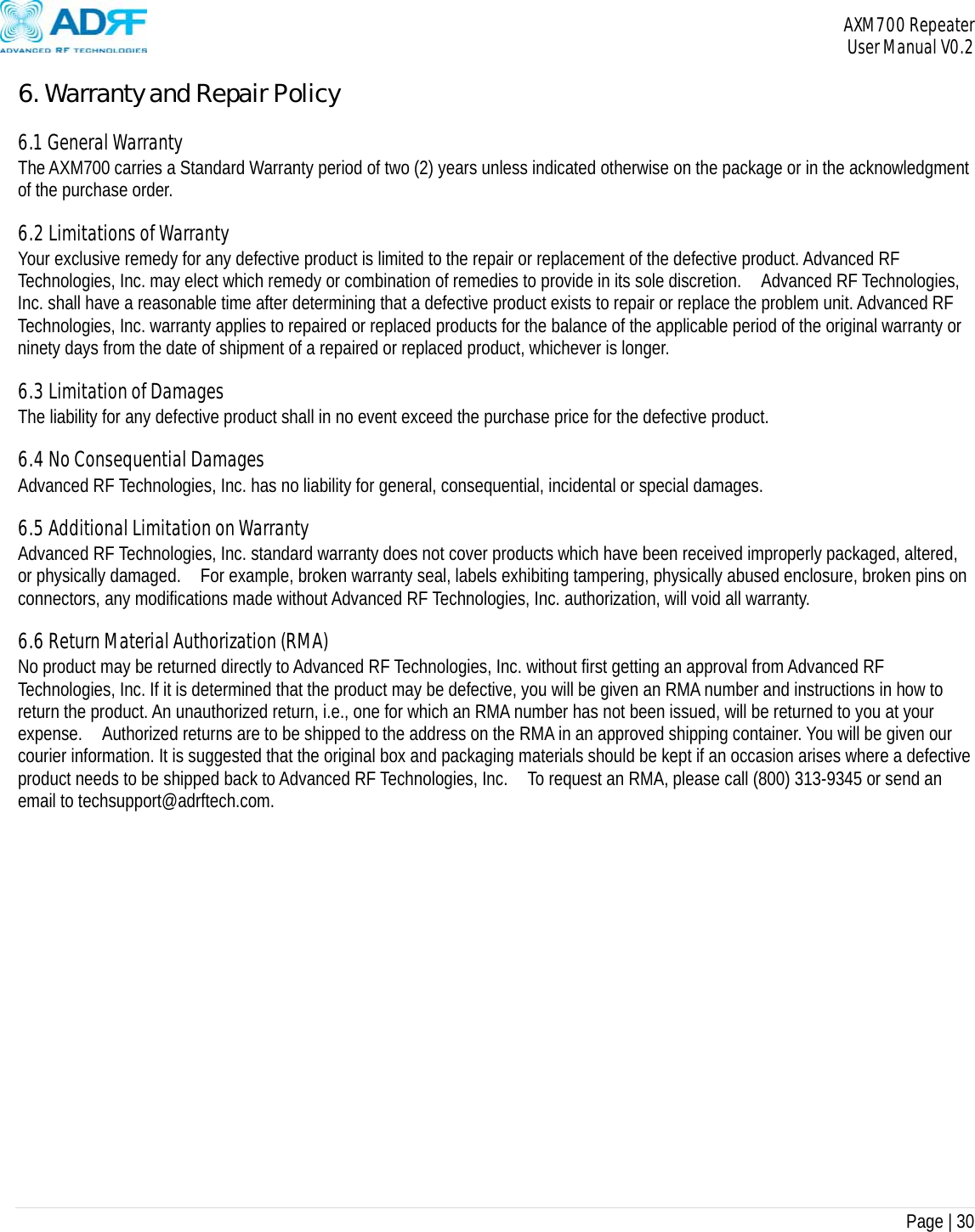
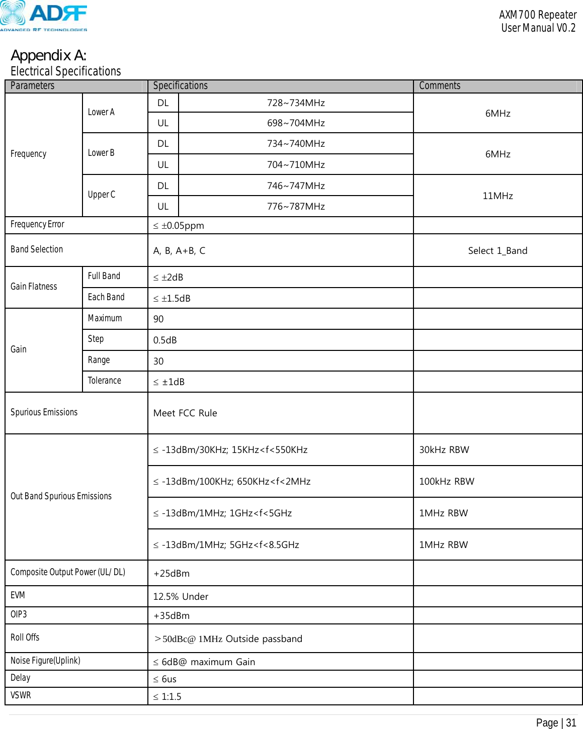
User Manual
Discussion / Help
Navigation