Advanced RF Technologies AXM700 RF Repeater (Bi-Directional Amplifier) User Manual
Advanced RF Technologies, Inc. RF Repeater (Bi-Directional Amplifier)
Users Manual
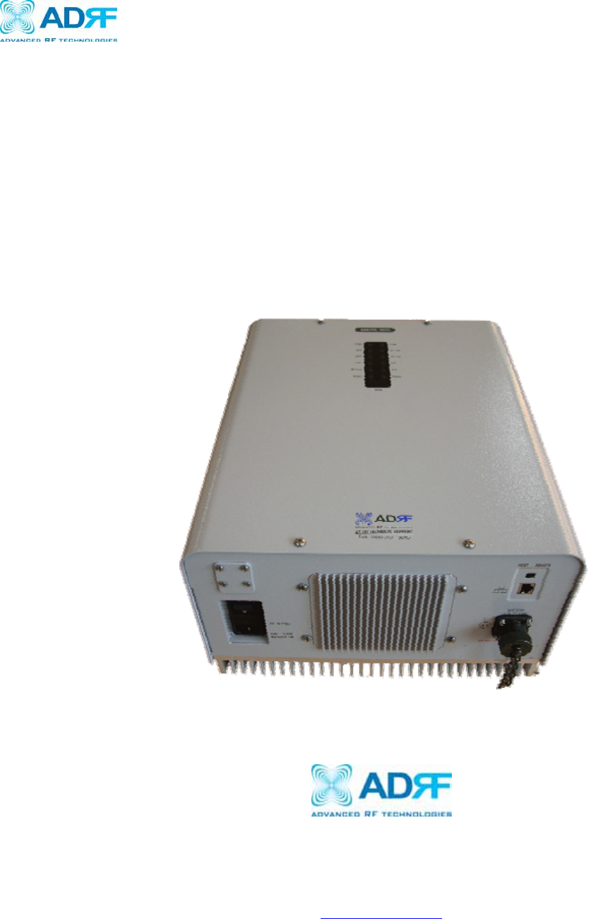
AXM700
USER MANUAL
Version 0.2
3116 Vanowen St.
Burbank, CA 91505
Tel: 818-840-8131
Fax: 818-840-8138
www.adrftech.com

AXM700 Repeater
User Manual V0.2
Page | 2
Glossary
The following is a list of abbreviations and terms used throughout this document.
Abbreviation/Term Definition
AGC Automatic Gain Control
ALC Automatic Level Control
AROMS ADRF’ Repeater Operation and Management
System
BTS Base Transceiver Station
CDMA Code Division Multiple Access
CFE Compact Front End
CW Continuous Wave (un-modulated signal)
DAS Distributed Antenna System
DL Downlink
Downlink The path covered from the Base Transceiver
Station (BTS) to the subscribers service area via
the repeater
HPA High Power Amplifier
HW Hardware
IF Intermediate Frequency
LNA
LTE Low Noise Amplifier
Long Term Evolution
MS Mobile Station
PLL Phased Locked Loop
PS Power Supply
RF Radio Frequency
SQE Signal Quality Estimate
SW Software
UL Uplink
Uplink The path covered from the subscribers service
area to the Base Transceiver Station(BTS) via the
repeater
VSWR Voltage Standing Wave Ratio

AXM700 Repeater
User Manual V0.2
Page | 3
Released version: 0.1
Information in this document is subject to change without notice.
Advanced RF Technologies, Inc. 1996-2010.
All rights reserved.
Please send comments to:
E-Mail: info@adrftech.com
Phone: (818) 840-8131
(800) 313-9345
Fax: (818) 840-8138
Address: Advanced RF Technologies, Inc.
Attention: Technical Publications Department
3116 W. Vanowen St.
Burbank, CA 91505
USA
www.adrftech.com
Revision History
Version Author Description Date
0.1 Sun Kim Initial Release April 19, 2010
0.2 Louis Lee Updated manual for UL and FCC
requirements May 17, 2010

AXM700 Repeater
User Manual V0.2
Page | 4
TABLE OF CONTENTS
1. AXM700 REPEATER ....................................................................................................................................... 6
1.1 Introduction ............................................................................................................................................... 6
1.1.1 Highlights ........................................................................................................................................ 6
1.1.2 Parts List .......................................................................................................................................... 7
1.1.3 Repeater Quick View ....................................................................................................................... 8
2. WARNINGS AND HAZARDS ......................................................................................................................... 9
3. AXM700 OVERVIEW ..................................................................................................................................... 11
3.1 Operation Modes ......................................................................................................................................11
3.1.1 Local Web-GUI ..............................................................................................................................11
3.1.2 Remote NMS (Modem Option) ......................................................................................................11
3.2 Front Panel LED .......................................................................................................................................11
3.3 Switches and Ports ................................................................................................................................... 12
3.3.1 Power Switch................................................................................................................................. 12
3.3.2 Battery Port ................................................................................................................................... 12
3.3.3 Ethernet Port and Host/Remote Switch ......................................................................................... 13
3.4 Installation ............................................................................................................................................... 13
3.4.1 Tools .............................................................................................................................................. 13
3.4.2 Procedure ....................................................................................................................................... 13
3.4.3 Grounding...................................................................................................................................... 15
3.4.4 Antenna Separation/Isolation ........................................................................................................ 16
3.4.5 Line of Sight .................................................................................................................................. 17
4. AXM700 WEB-GUI SETUP .......................................................................................................................... 18
4.1 Repeater/PC Connection Using Web-GUI .............................................................................................. 18
4.2 Status Tab ................................................................................................................................................. 19
4.3 Control Tab .............................................................................................................................................. 21
4.4 Install Tab ................................................................................................................................................ 24
4.5 System ..................................................................................................................................................... 26
4.5.1 System: Account: ........................................................................................................................... 26
4.5.2 System: User Log .......................................................................................................................... 27
4.5.3 System: F/W Update ..................................................................................................................... 27
4.6 Help ......................................................................................................................................................... 28
4.7 Logout ...................................................................................................................................................... 28
5. MAINTENANCE GUIDE FOR AXM700 REPEATER ............................................................................. 29
5.1 Periodic Inspection Checklist .................................................................................................................. 29
5.2 Preventive Measures for Optimal Operation ........................................................................................... 29
5.2.1 Recommendations ......................................................................................................................... 29
5.2.2 Precautions .................................................................................................................................... 29
6. WARRANTY AND REPAIR POLICY ......................................................................................................... 30
6.1 General Warranty ..................................................................................................................................... 30
6.2 Limitations of Warranty ........................................................................................................................... 30
6.3 Limitation of Damages ............................................................................................................................ 30
6.4 No Consequential Damages..................................................................................................................... 30
6.5 Additional Limitation on Warranty .......................................................................................................... 30
6.6 Return Material Authorization (RMA) .................................................................................................... 30

AXM700 Repeater
User Manual V0.2
Page | 5
APPENDIX A: ..................................................................................................................................................... 31
Electrical Specifications ................................................................................................................................ 31
Mechanical Specifications ............................................................................................................................. 32
Environmental Specifications ........................................................................................................................ 32
Power Specifications ..................................................................................................................................... 32
Other Specifications ...................................................................................................................................... 32

AXM700 Repeater
User Manual V0.2
Page | 6
1. AXM700 Repeater
1.1 Introduction
The AXM700 is ideal for upgrading existing 3G (PCS/Cellular) systems with 4G LTE services, and can also serve as
feeder source to active DAS.
1.1.1 Highlights
• Support Lower A, Lower B, Lower A + B, and Upper C sub-band filtering
• Digital filtering with sharp roll-off (>50 dBc @ + 1 MHz from sub-band edge)
• Remote monitoring and control capability using our Web-based GUI
• 90 dB of max gain and 25 dBm max output power
• Front panel LEDs provide signal strength and alarm status
• Optional integrated modem for remote access and alarming
• Configurable network setting in order to interface with ADRF's OmniBox or 3rd party external modem boxes
• Detachable wall mount brackets allow for a more efficient installation
AXM700 Repeater
User Manual V0.2
Page | 7
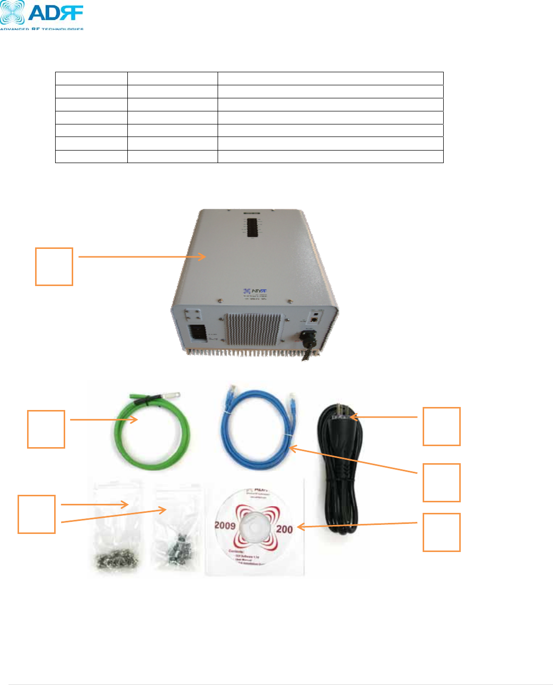
1.1.2 Parts List
Label Quan
t
ity Description
A 1 AXM700 Repeater
B 1 Ground Cable
C 1 Set Wall Mounting Anchor Bolts/Screws
D 1 Ethernet Cable (Crossover)
E 1 Documentation CD**
F 1 AC Power Cable
** CD includes: User Manual, Quick-Start Guide, and Troubleshooting Guide
Figure A – AXM700 Repeater Parts List
Table 1 – Parts List
A
F
D
E
B
C
AXM700 Repeater
User Manual V0.2
Page | 8
1.1.3 Repeater Quick View
AXM700 Repeater
User Manual V0.2
Page | 9
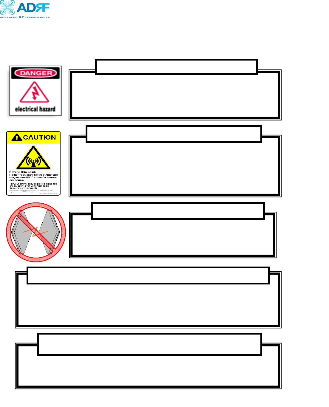
2. Warnings and Hazards
Actual separation distance is determined upon gain of antenna used.
Please maintain a minimum safe distance of at least 60 cm while operating near the donor and the server
antennas. Also, the donor antenna needs to be mounted outdoors on a permanent structure.
RF EXPOSURE & ANTENNA PLACEMENT Guidelines
Opening or tampering the AXM700 will void all warranties.
WARRANTY
Operating the AXM700 with antennas in very close proximity facing each other
could lead to severe damage to the repeater.
WARNING! DAMAGE TO REPEATER
Working with the repeater while in operation, may expose the technician to RF
electromagnetic fields that exceed FCC rules for human exposure. Visit the FCC
website at www.fcc.gov/oet/rfsafety to learn more about the effects of exposure to RF
electromagnetic fields.
WARNING! EXPOSURE TO RF
Opening the AXM700 could result in electric shock and may cause severe
injury.
WARNING! ELECTRIC SHOCK
AXM700 Repeater
User Manual V0.2
Page | 10
Caution: For continued protection against risk of fire, replace only with same type and rating of
fuse.
NOTE: This equipment has been tested and found to comply with the limits for a Class A
digital device, pursuant to part 15 of the FCC Rules. These limits are designed to provide
reasonable protection against harmful interference when the equipment is operated in a
commercial environment. This equipment generates, uses, and can radiate radio frequency
energy and, if not installed and used in accordance with the instruction manual, may cause
harmful interference to radio communications. Operation of this equipment in a residential
area is likely to cause harmful interference in which case the user will be required to correct
the interference at their own expense.
FCC Part 15 Class A
Lithium Battery: CAUTION. RISK OF EXPLOSION IF BATTERY IS REPLACED BY INCORRECT
TYPE. DISPOSE OF USED BATTERIES ACCORDING TO INSTRUCTIONS.
Ethernet Instructions: This equipment is for indoor use only. All cabling should be limited to
inside the building.
AXM700 Repeater
User Manual V0.2
Page | 11
3. AXM700 Overview
3.1 Operation Modes
3.1.1 Local Web-GUI
The AXM700 can be accessed locally by connecting a RJ-45 crossover cable from your laptop to the Ethernet port of the
repeater. Once a connection is established, launch your web browser and type http://192.168.63.1 in the address bar. A
popup window prompting for a user name and password will appear. Input your login credentials to gain access to the
repeater.
3.1.2 Remote NMS (Modem Option)
The AXM700 can support an optionally CDMA wireless modem in order to monitor and adjust the settings of the repeater
from a remote location. A computer with internet connection can be used to gain access to the repeater from a remote
location. To gain access to the repeater from a remote location, launch you web browser and type the static IP address that
has been assigned to the wireless modem and a popup window prompting for a user name and password will appear. Input
your login credentials to gain access to the repeater.
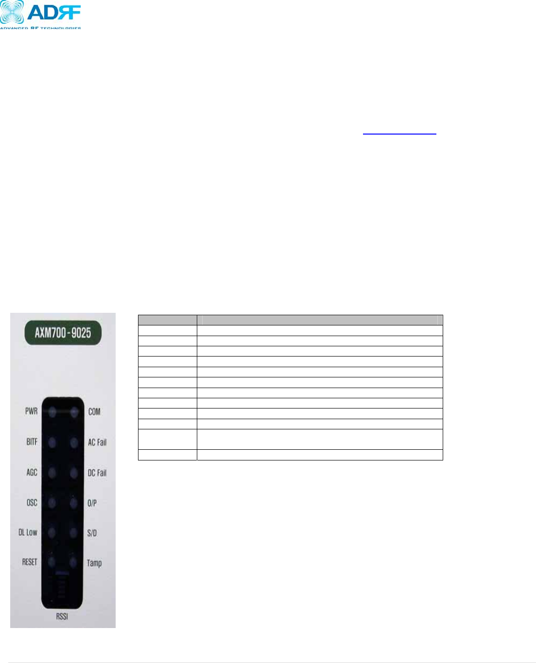
3.2 Front Panel LED
A general overview of the status of the repeater can be seen by looking at the LED indicators on the front of the repeater.
Indicator Description
PWR Indicates whether or not repeater is being powered
BITF Test to see that the modules is functioning
AGC Indicates whether or not AGC is being utilized
OSC Detects if oscillation is occurring
DL Low Detects is DL RSSI signal is below the specified threshold
RESET Indicates whether or not an unauthorized reset has occurred
COM Indicates that the repeater is communicating with the laptop
AC Fail Indicates that the repeater is not receiving enough AC Power
DC Fail Indicates that the repeater is not receiving enough DC Power
O/P Indicates that the repeater is in the state of RF Overpower
S/D Indicates that the repeater is performing the built-in shutdown
routine to protect itself from further damage
Tamper Detects if the settings of the repeaters have been changed
AXM700 Repeater
User Manual V0.2
Page | 12
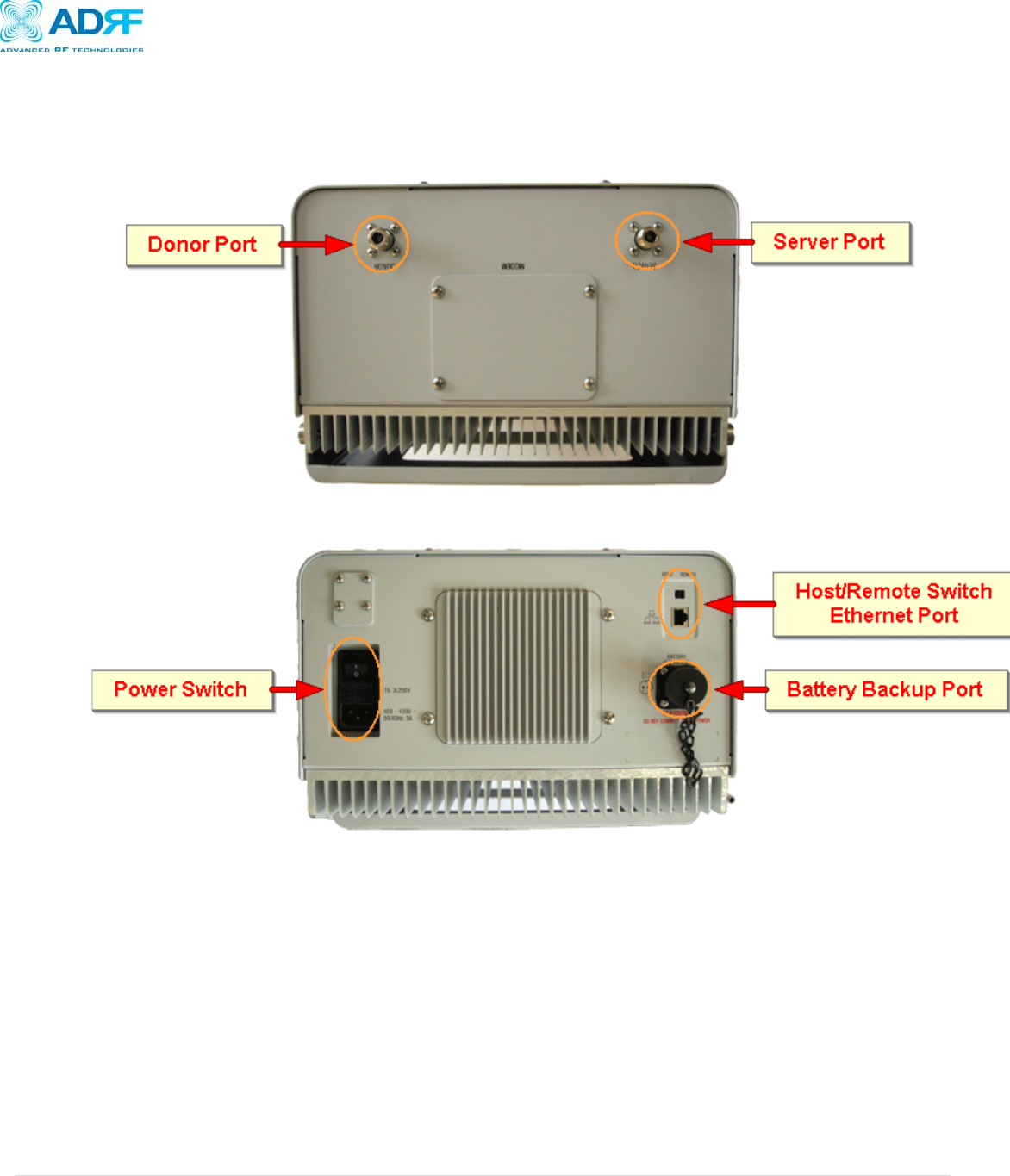
3.3 Switches and Ports
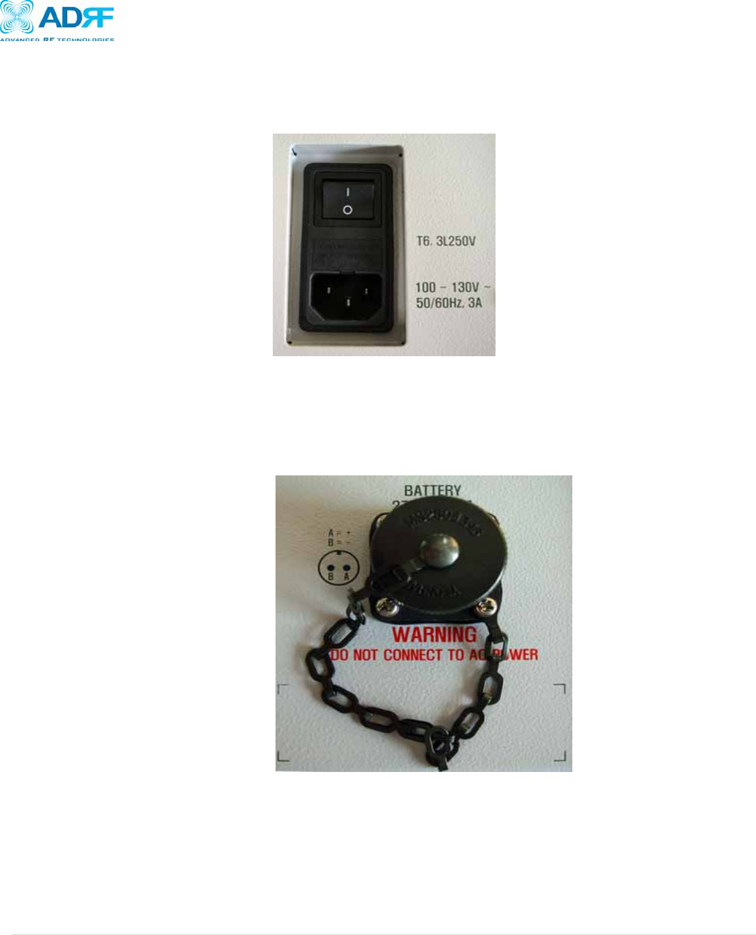
3.3.1 Power Switch
The AC Power on/off switch is located at the back panel of repeater. The switch should be powered on after the repeater has
been physically installed properly.
Figure 1: AXM700 Repeater Power Switch View
3.3.2 Battery Port
The Battery Port is to be used in conjunction with the ADRF-BBU (Optional Battery Backup Unit). The ADRF-BBU offers up
to 8 hours of battery backup power to avoid any possible downtime due to power failure. If a backup battery is utilized,
please connect the battery to the unit via the external battery port as shown in Figure 4.
Figure 2: Battery Port
Note: Please contact ADRF Technical Support for assistance if you are unfamiliar with the installation procedure of our
battery box.
AXM700 Repeater
User Manual V0.2
Page | 13
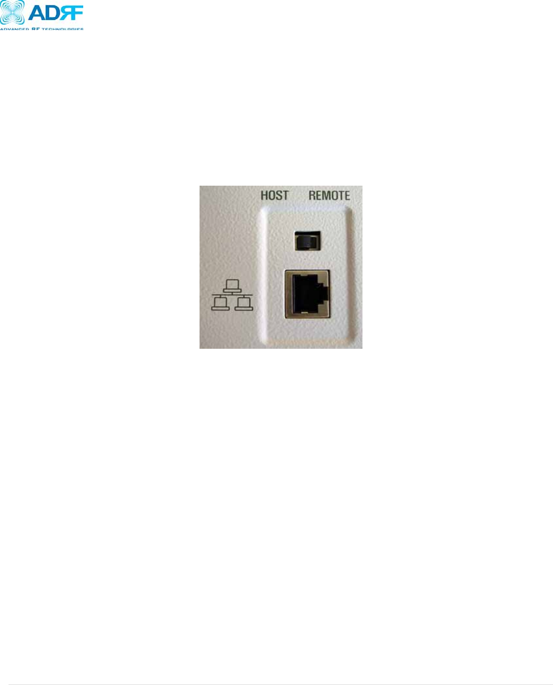
3.3.3 Ethernet Port and Host/Remote Switch
• The Ethernet port as shown in Figure 5 is used to interface with the repeater locally. A RJ-45 crossover cable is required in
order to establish a connection with the unit.
• Host/Remote switch is to be used when an external modem box is being used
o Host Mode: DHCP is enabled. Any computer set to “Obtain an IP address automatically” will be assigned an IP
address by the repeater. When the repeater is set to Host Mode the IP address of the unit is 192.168.63.1
o Remote Mode: DHCP is disabled. This mode should only be used when an external modem box is present. By
default, then IP address of the unit is set to 192.168.63.5 and can be changed by setting the repeater to Host Mode
and specifying and IP address in the Modem Box Setting under the Install Tab of our Web-GUI.
Figure 3: Ethernet Port and Host/Remote Switch
3.4 Installation
3.4.1 Tools
The following tools are required to mount the AXM700 to the wall:
• Phillips screwdriver
• Power drill
3.4.2 Procedure
Four mounting holes are located on the wall-mounting bracket to attach it to the wall. The wall bracket must be securely
attached to sufficiently carry the weight of the AXM700, which is bolted to the wall bracket through the four aligned mounting
holes.
Installation Procedure
① Verify that the Repeater and Mounting Bracket are in good condition.
② Drill holes in the installation surface and insert the anchor bolts.
③ Set the mounting bracket against the wall.
④ Using the Hooks on top, set the Repeater against the mounting bracket.
⑤ Using the anchor bolts attach the Repeater to the Bracket.
⑥ Make sure the Repeater is securely attached.
⑦ Connect the GND cable.
⑧ Connect the Antenna cable.
⑨ Connect the Power.
⑩ Using a laptop, setup the Repeater.
AXM700 Repeater
User Manual V0.2
Page | 14
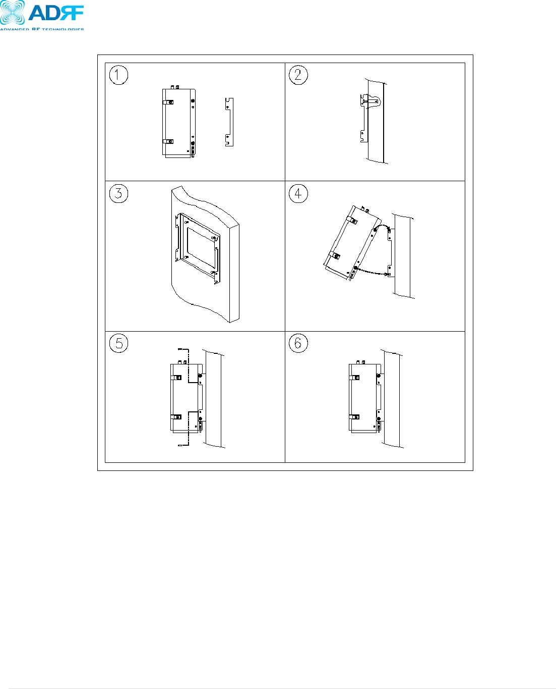
Figure 4: AXM700 Mounting Instructions
1. Unpack the repeater and the mounting bracket from the box
2. Install the anchor bolts to the wall
3. Screw the mounting bracket to the wall using the anchor bolts
4. Tilt the repeater as shown in Figure 4 above and place top mounting loop over the upper hook of the
mounting bracket
a. Gently lower the repeater into place so that it is hanging vertically
5. Fasten the bracket to the repeater as shown in Figure 5
6. Once completed, the repeater should look like Figure 6
AXM700 Repeater
User Manual V0.2
Page | 15
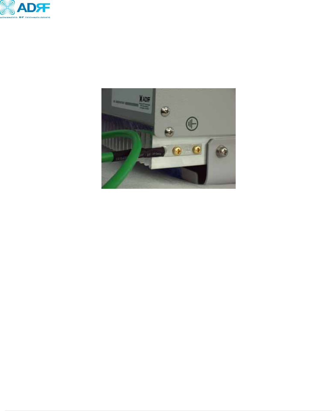
3.4.3 Grounding
A ground cable is included in the box. The ground cable should be connected to the Right side of AXM700 before the repeater
is turned on.
Figure 5: Ground Cable Connection
AXM700 Repeater
User Manual V0.2
Page | 16
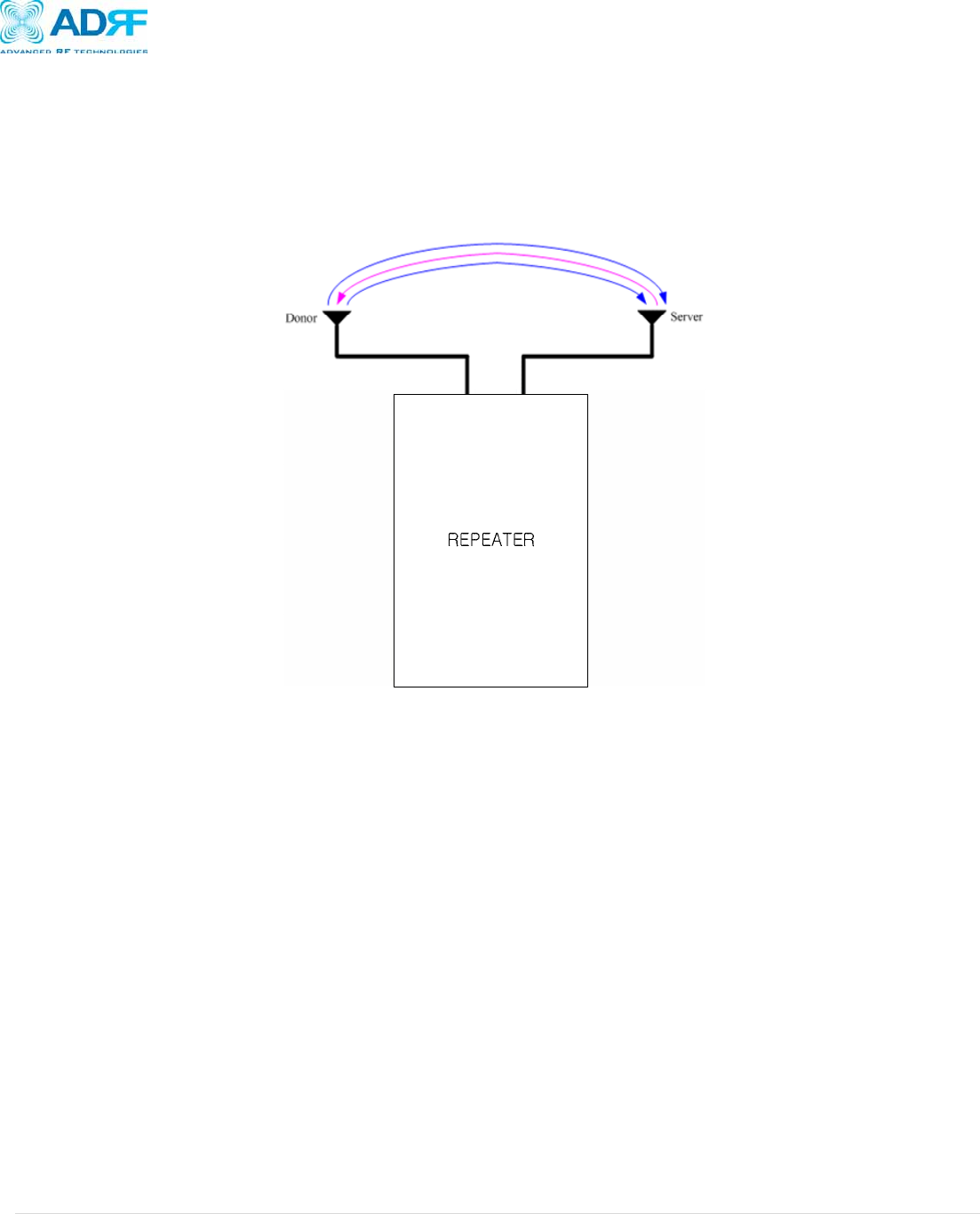
3.4.4 Antenna Separation/Isolation
Separation between the antennas is necessary to prevent oscillation. Oscillation occurs when the signal entering the system
continually reenters, due to the lack of separation between the donor and server antennas. In other words, the signal is being fed
back into the system. This creates a constant amplification of the same signal. As a result, the noise level rises above the signal
level.
Figure 6: RF Repeater Oscillation
To prevent feedback, the donor and server antennas must be separated by an appropriate distance to provide sufficient isolation.
Isolation is attained by separating antennas a sufficient distance so that the output of one antenna does not reach the input of the
other. This distance is dependent on the gain of the repeater.
A sufficient isolation value is 13 ~ 15 dB greater than the maximum gain of the repeater. For example, if the gain of the repeater is
50 dB, then an isolation of 63 ~ 65 dB or greater is required. In the same manner, because the AXM700 has a maximum gain of
90 dB in case of AXM700, it requires an isolation of at least 103 ~ 105 dB.
AXM700 Repeater
User Manual V0.2
Page | 17
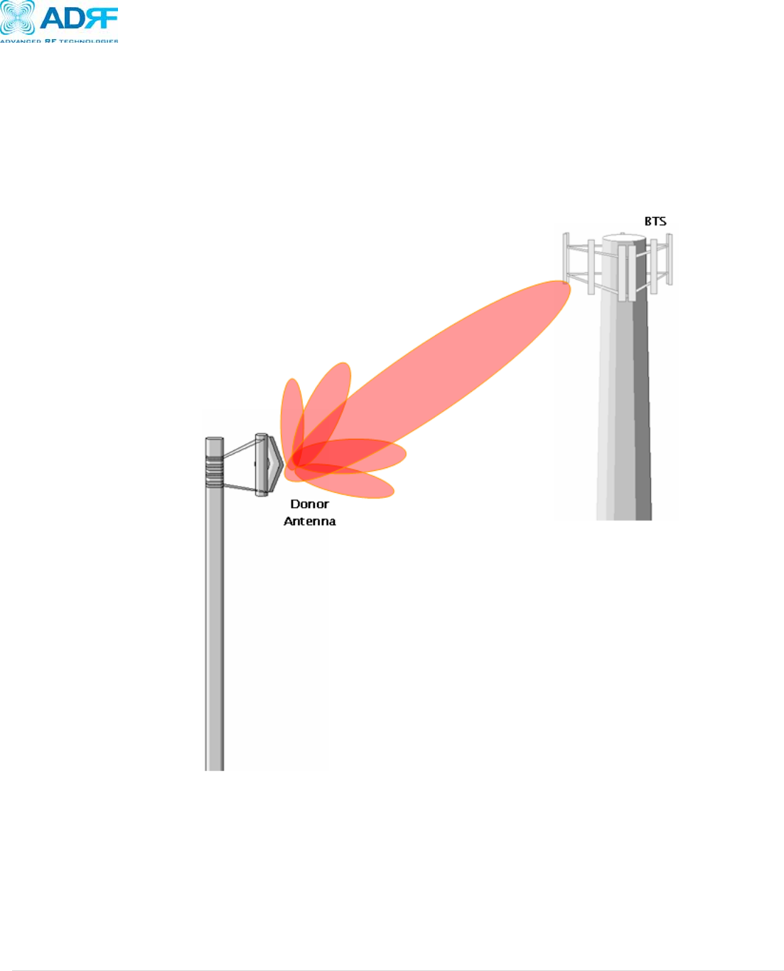
3.4.5 Line of Sight
The donor antenna which points towards the base station typically has a narrow beam antenna pattern. As a result, a slight
deviation away from the direction of the BTS can lead to less than optimum results. In addition, obstacles between the repeater
and the BTS may impair the repeater from obtaining any BTS signal. As a result, the repeater cannot transmit signal to the
coverage area. Therefore, a direct line of sight to the BTS for the donor antenna is vital to the function of a repeater. For the
same reason, placing the server antenna in direct line of sight of the coverage area is also necessary.
Figure 17 - Direct Line of Sight to the BTS
AXM700 Repeater
User Manual V0.2
Page | 18
4. AXM700 Web-GUI Setup
The Web-GUI allows the user to communicate with the repeater either locally or remotely. To connect to the repeater locally, you will
need a laptop with an Ethernet port and a RJ-45 crossover cable. To connect to the repeater remotely, you will need to have an
active internet connection and the repeater must have either an internal modem or an Omnibox (ADRF Modem Box) connected to the
repeater.
4.1 Repeater/PC Connection Using Web-GUI
A. Verify that your Local Area Connection is set to Obtain an IP address automatically under the Internet Protocol (TCP/IP)
properties
• If you are connecting to the unit remotely, then skip steps A and B.
B. Connect the RJ-45 crossover cable between the laptop’s Ethernet port and the repeater’s Ethernet port
C. Launch Microsoft Internet Explorer (Version 7.0 or below)
D. Type the following IP address into the address bar of Microsoft Internet Explorer: http://192.168.63.1
• If you are connecting to the unit remotely, then type the IP address of the modem to connect to the unit
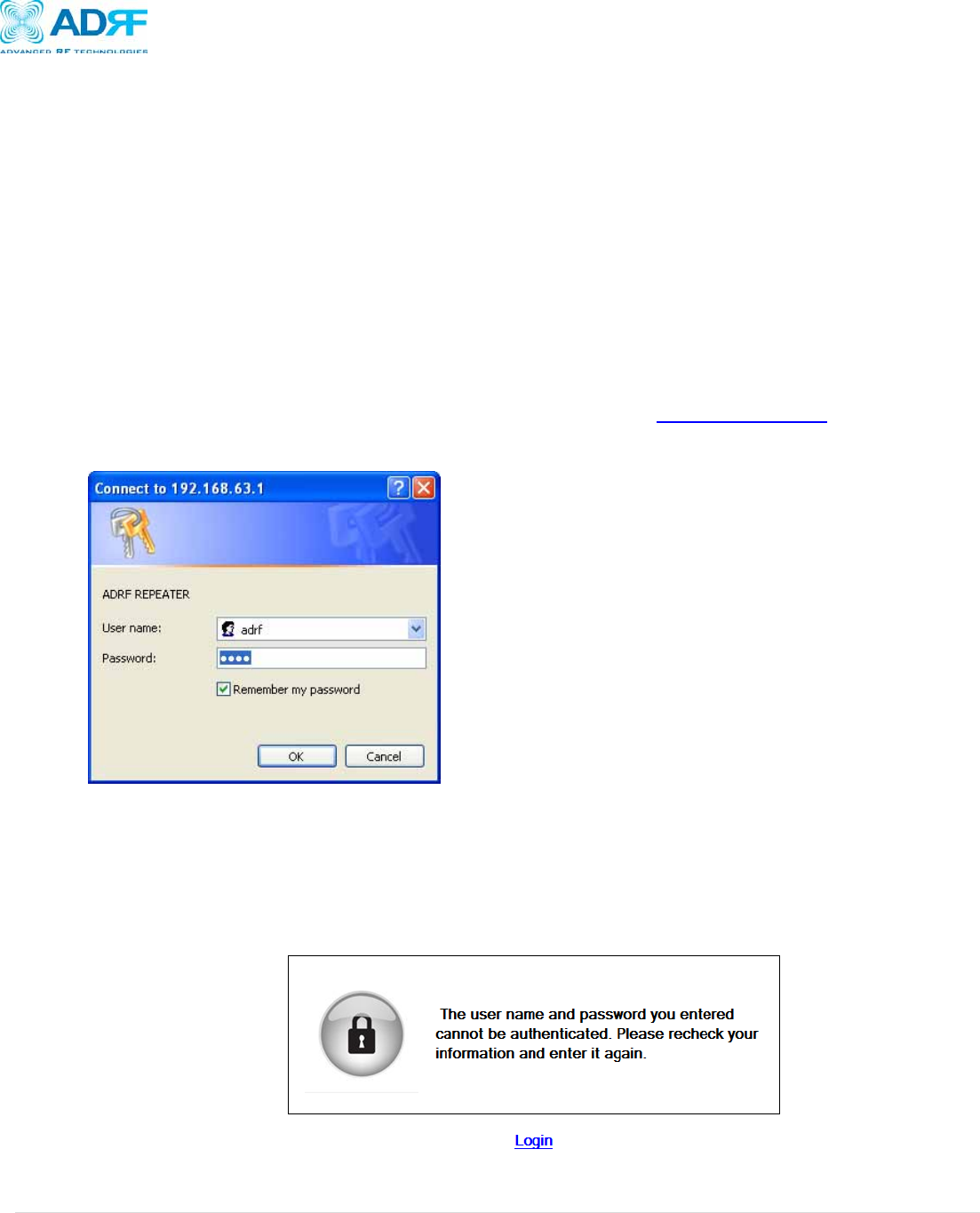
E. The following login screen will appear:
If you are not the Administrator, please type in your assigned username & password which you should have received from the
Administrator.
The default username and password for the General User is adrf & adrf, respectively.
If the username & password is typed in incorrectly, the following screen will appear:
AXM700 Repeater
User Manual V0.2
Page | 19
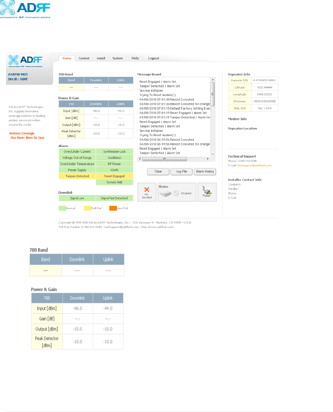
4.2 Status Tab
The Status Tab allows the user to see a snapshot of the system to see if any issues need to be addressed.
• Band: Displays the bands that are currently being utilized
• Power & Gain: Displays the Input, Gain, and Output for both Downlink and Uplink
AXM700 Repeater
User Manual V0.2
Page | 20
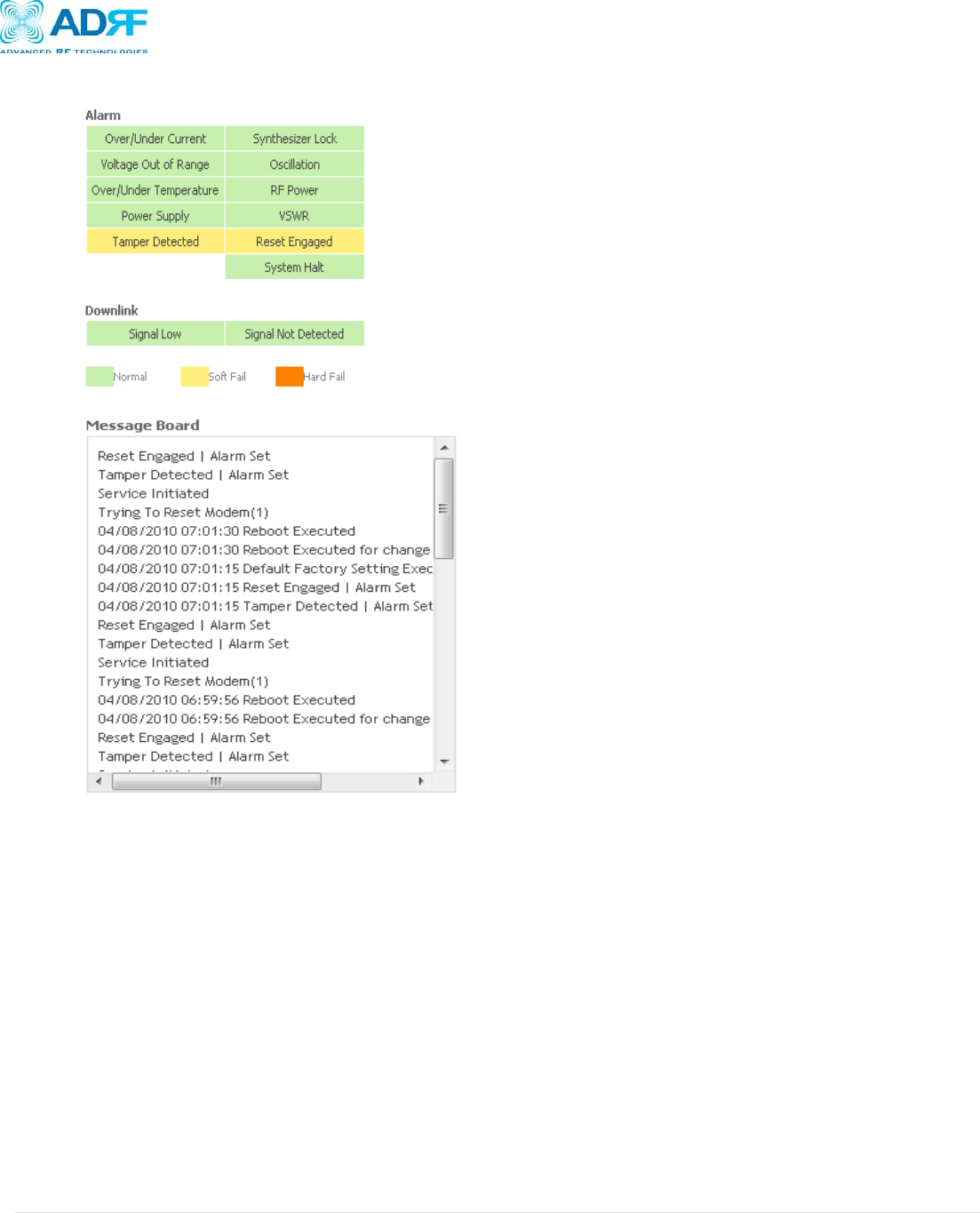
• Alarm: Displays 13 alarms with three different status conditions (Normal, Soft Fail or Hard Fail).
• Message Board: Displays the 20 most recent events.
• Clear: Clears the content that is currently being displayed on the Message Board
• Log File: Downloads the system Log File (events and alarms) to your computer
• Alarm History: Downloads the Alarm History log (alarms only) to your computer
• Installation: Displays whether or not the installation routine has been run (Not Installed or Installed)
• Modem: Displays the status of the modem
o Disabled- No internal modem is present
o Not Connected- Internal modem is detected, but no connection to the network has been established
o Connected- Internal modem is detected and a connection to the network has been established
• Repeater Info: Displays the serial number, latitude, longitude, firmware version, Web-GUI version
• Modem Info: Displays the ESN (DEC), MDN, and IP Address of the internal modem
• Repeater Location: Displays the address where the repeater is installed
• Technical Support: Displays ADRF’s Technical Support contact information
• Installer Contact Info: Displays the installer’s name, phone and e-mail address
Note: Once successfully logged in, the repeater model name and the site/cascade ID will be displayed
on the top of all the windows (except for the Main Window).
AXM700 Repeater
User Manual V0.2
Page | 21
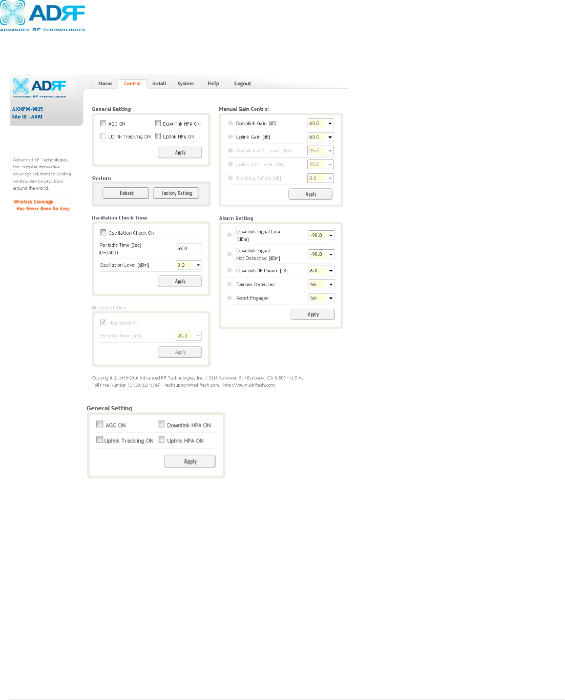
4.3 Control Tab
The Control Tab allows the user to adjust the settings of the repeater.
General Setting
• AGC ON: Enables or disables AGC (Automatic Gain Control)
• Uplink Tracking ON: Enables or disables the Uplink Tracking Feature
o Uplink Tracking adjusts the Uplink Gain to meet the Uplink Tracking Offset value
• Downlink HPA ON: Enables or disables the DL HPA
• Uplink HPA ON: Enables or disabled the UL HPA
AXM700 Repeater
User Manual V0.2
Page | 22
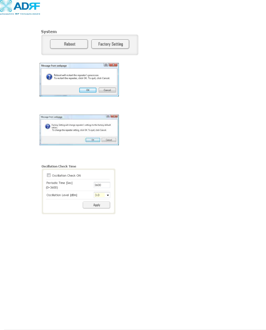
System
• Reboot: Clicking the reboot button will have the following popup show up:
Click OK to reboot the repeater or click Cancel to exit out
• Factory Setting: Resets the repeater to the original factory settings
Click OK to reset the settings to the Factory Default settings or Cancel to exit out
Oscillation Check Setting
• Oscillation Check ON: Enables or disables oscillation check
• Periodic Time: Allows the use to specify how often the repeater runs the oscillation check
• Oscillation Level: Allows the user to adjust the sensitivity level of the oscillation detection level
AXM700 Repeater
User Manual V0.2
Page | 23
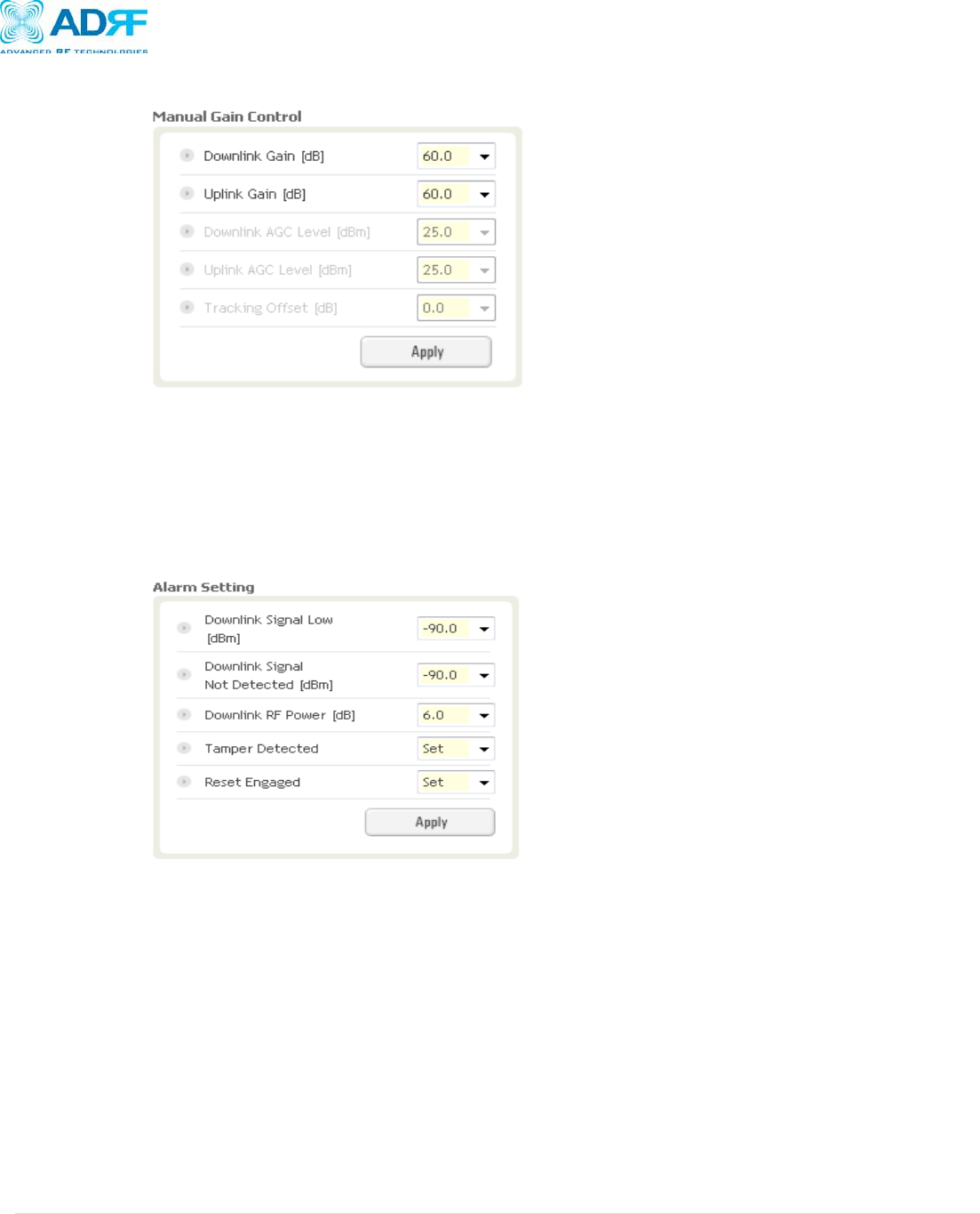
Manual Gain Control
• Downlink Gain: Allows the DL gain to be adjusted manually when AGC is OFF
• Uplink Gain: Allows the UL gain to be adjusted manually when AGC is OFF
• Downlink AGC Level: Allows the user to set the DL gain when AGC is enabled
• Uplink AGC Level: Allows the user to set the UL gain when AGC is enabled
• Uplink Tracking Offset: This offset value determines how many dB lower the uplink gain value will be relative to the
downlink gain value
Alarm Setting
• Downlink Signal Low: Allows the user to specify how weak the signal can be before triggering a “Downlink Signal Low” soft-
fail alarm
• Downlink Signal Not Detected: Allows the user to specify the how weak the signal can be before triggering a “Signal Not
Detected” soft-fail alarm
• Downlink RF Power: Allows the user to set a maximum deviation value for the downlink RF power
o For example, if the input signal is -50 dBm and the gain is set to 60 dB, the expected output power should be 10 dBm.
If the Downlink RF Power alarm value is set to 6dB, then if the output power is below 4 dBm, then this will trigger a
soft-fail alarm
• Tamper Detected: Allows the tamper detection feature to be enabled or disabled
• Reset Engaged: Allows the Reset Engaged functioned to be enabled or disabled
AXM700 Repeater
User Manual V0.2
Page | 24
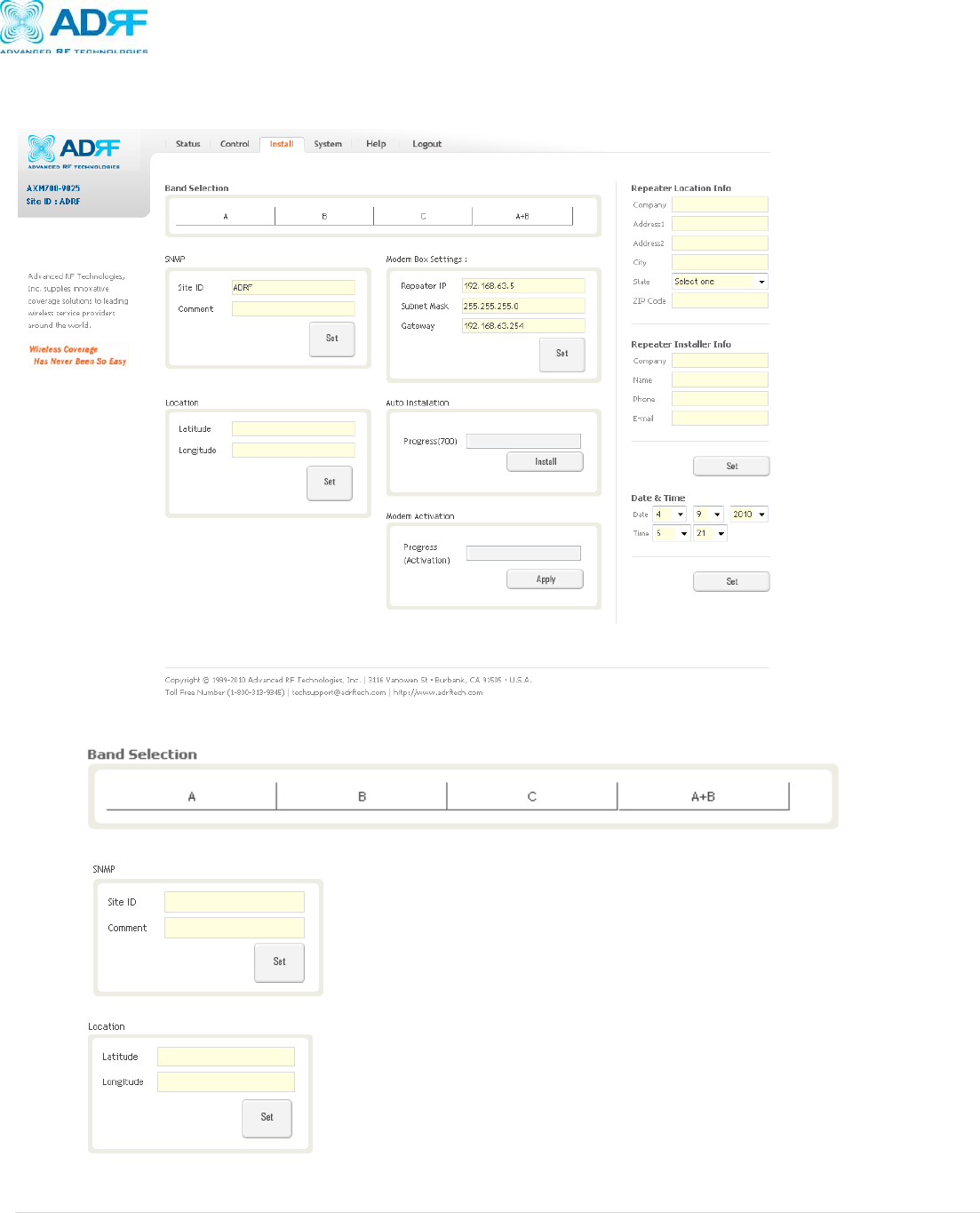
4.4 Install Tab
Allows the user change the settings required to run the installation routine properly.
• Band Selection: Allows the user to select the band(s) they would like to utilize
• SNMP: Type in the assigned site/cascade ID and manager IP address
• Location: Displays the physical address where the repeater is installed
AXM700 Repeater
User Manual V0.2
Page | 25
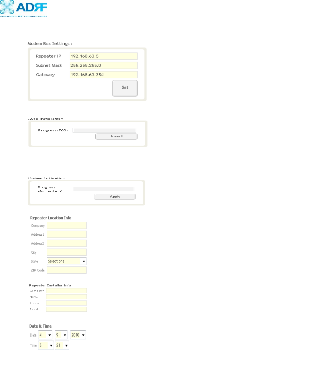
• Modem Box Settings: Allows the user to specify the IP address, subnet mask, and gateway for the repeater when the
Host/Remote switch is set to Remote.
• Auto Installation: Runs the automated installation routine that will run basic checks to ensure that the repeater can function in
the environment
• Modem Activation: Run the automated modem activation procedure which will attempt to activate a modem that has already
been provisioned. Once the modem activation procedure is complete, the repeater will automatically try to establish a
connection.
• Repeater Location Info: Information about the location physical location of the repeater can be stored here
• Repeater Installer Info: Information about the Installer can be stored here
• Date & Time: The Date and Time settings can be adjusted here
AXM700 Repeater
User Manual V0.2
Page | 26
4.5 System
The System tab allows the user to perform firmware updates, add/remove user accounts, and change the login credentials of the
Administrator.
4.5.1 System: Account:
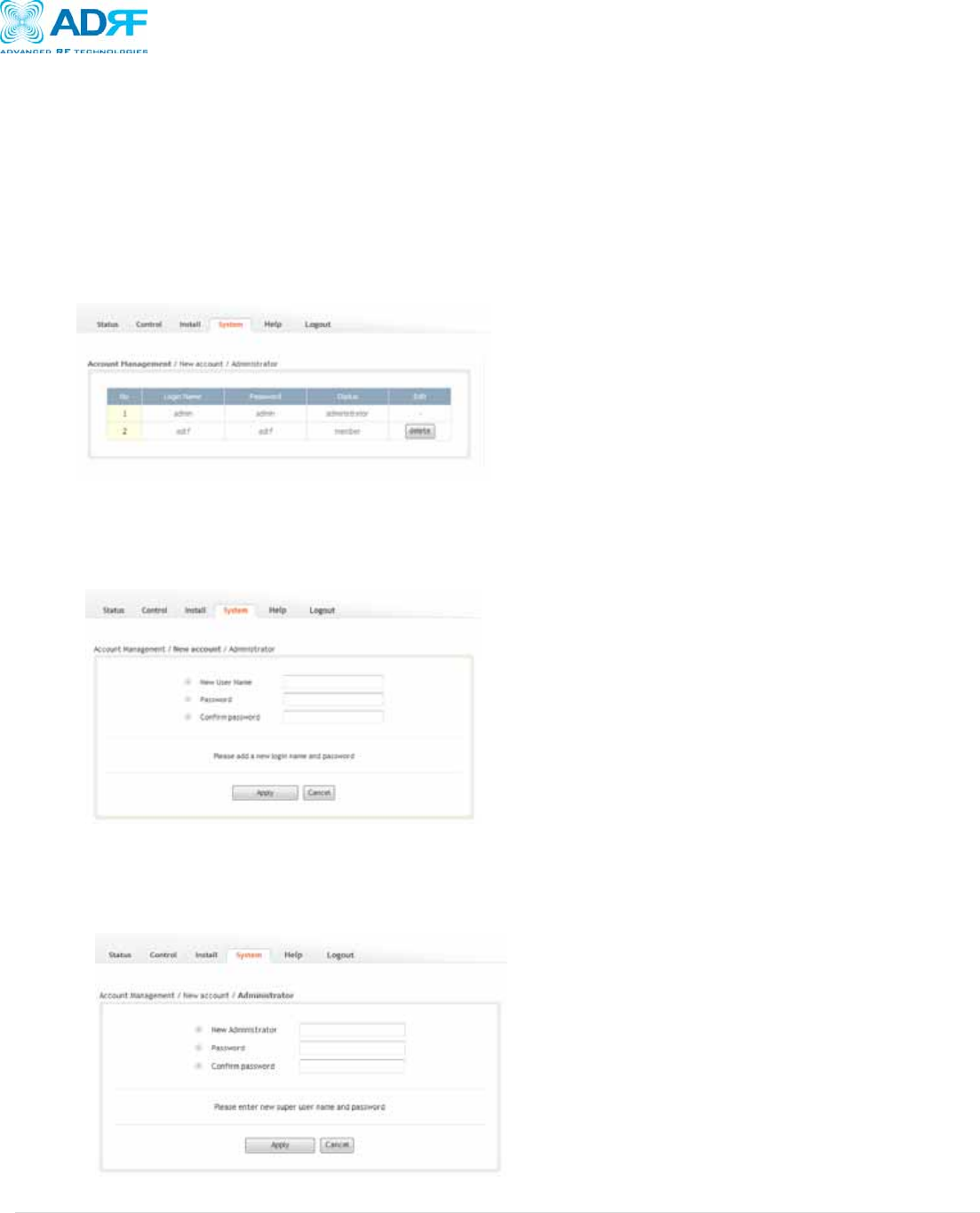
4.5.1.1 System: Account Management
The Account Management section will allow the Administrator to delete any user account. Please note that the Account
Management section is only available if you are logged into the system as the Administrator. To delete a user account click
on the Account Management link and under the Delete column, click on the delete button.
4.5.1.2 System: New Account
The New account section allows the Administrator to create a new user account. Please note that the New account
section is only available if you are logged into the system as the Administrator. To create a new user account click on the
New account link and fill in the fields highlighted in yellow as shown below.
4.5.1.3 System: Administrator
The Administrator section allows the Administrator to change their login credentials. Please note that the Administrator
section is only available if you are logged into the system as the Administrator. To change the login/password of the
administrator, click on the Administrator link and fill in the sections highlighted in yellow as shown below.
AXM700 Repeater
User Manual V0.2
Page | 27
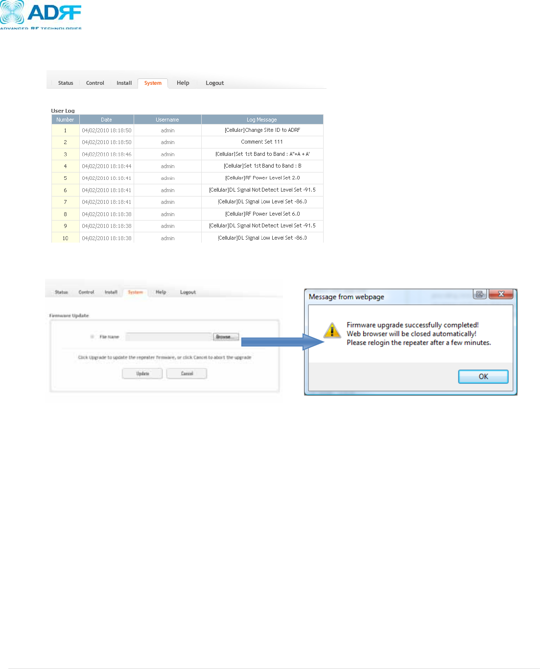
4.5.2 System: User Log
The User Log displays all the system activities in chronological order.
4.5.3 System: F/W Update
To perform a firmware update, click on the System tab then click on F/W Update and screen on the left will appear:
• Click on the Browse… button and locate the firmware file
• Click on the Upload button to perform the firmware update
• Once the firmware update is complete, the following popup message on the right will appear:

AXM700 Repeater
User Manual V0.2
Page | 28
4.6 Help
If an internet connection is available, clicking on the Help Tab will redirect the user to our Technical Support page.
4.7 Logout
Clicking the Logout button will log the current user off the system.

AXM700 Repeater
User Manual V0.2
Page | 29
5. Maintenance Guide for AXM700 Repeater
5.1 Periodic Inspection Checklist
1. Check for loose connections between the repeater and antennas.
a. If connections are loose, make sure that all connections are tightly fastened properly.
2. Cables and connectors are in good condition.
3. Ensure that the repeater brackets are in good. condition and that the repeater is securely fastened
5.2 Preventive Measures for Optimal Operation
5.2.1 Recommendations
• Perform the Periodic Inspection Checklist quarterly or semi-annually.
5.2.2 Precautions
• Do not operate the repeater with the antennas in extremely close proximity to one another as this may cause
damage to the repeater.
• Do not change the parameters unless instructed to do so by an authorized supervisor.
• Do not move the repeater unless instructed to do so by an authorized supervisor.
• Do not detach any cables to the repeater unless repair of respective components is necessary.

AXM700 Repeater
User Manual V0.2
Page | 30
6. Warranty and Repair Policy
6.1 General Warranty
The AXM700 carries a Standard Warranty period of two (2) years unless indicated otherwise on the package or in the acknowledgment
of the purchase order.
6.2 Limitations of Warranty
Your exclusive remedy for any defective product is limited to the repair or replacement of the defective product. Advanced RF
Technologies, Inc. may elect which remedy or combination of remedies to provide in its sole discretion. Advanced RF Technologies,
Inc. shall have a reasonable time after determining that a defective product exists to repair or replace the problem unit. Advanced RF
Technologies, Inc. warranty applies to repaired or replaced products for the balance of the applicable period of the original warranty or
ninety days from the date of shipment of a repaired or replaced product, whichever is longer.
6.3 Limitation of Damages
The liability for any defective product shall in no event exceed the purchase price for the defective product.
6.4 No Consequential Damages
Advanced RF Technologies, Inc. has no liability for general, consequential, incidental or special damages.
6.5 Additional Limitation on Warranty
Advanced RF Technologies, Inc. standard warranty does not cover products which have been received improperly packaged, altered,
or physically damaged. For example, broken warranty seal, labels exhibiting tampering, physically abused enclosure, broken pins on
connectors, any modifications made without Advanced RF Technologies, Inc. authorization, will void all warranty.
6.6 Return Material Authorization (RMA)
No product may be returned directly to Advanced RF Technologies, Inc. without first getting an approval from Advanced RF
Technologies, Inc. If it is determined that the product may be defective, you will be given an RMA number and instructions in how to
return the product. An unauthorized return, i.e., one for which an RMA number has not been issued, will be returned to you at your
expense. Authorized returns are to be shipped to the address on the RMA in an approved shipping container. You will be given our
courier information. It is suggested that the original box and packaging materials should be kept if an occasion arises where a defective
product needs to be shipped back to Advanced RF Technologies, Inc. To request an RMA, please call (800) 313-9345 or send an
email to techsupport@adrftech.com.

AXM700 Repeater
User Manual V0.2
Page | 31
Appendix A:
Electrical Specifications
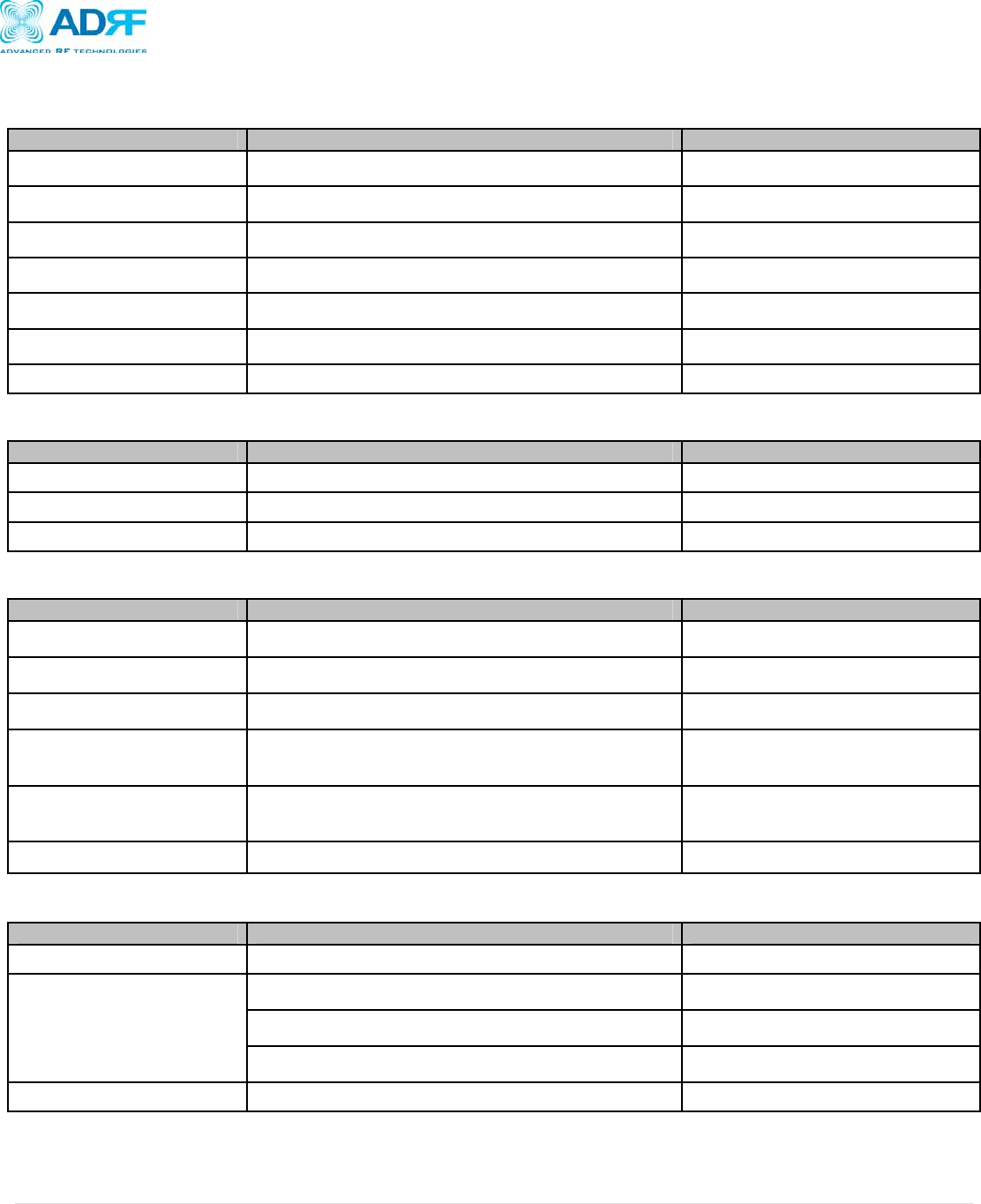
Parameters Specifications Comments
Frequency
Lower A DL 728~734MHz
6MHz
UL 698~704MHz
Lower B DL 734~740MHz
6MHz
UL 704~710MHz
Upper C DL 746~747MHz
11MHz
UL 776~787MHz
Frequency Error 0.05ppm
Band Selection A, B, A+B, C Select 1_Band
Gain Flatness Full Band 2dB
Each Band 1.5dB
Gain
Maximum 90
Step 0.5dB
Range 30
Tolerance ±1dB
Spurious Emissions Meet FCC Rule
Out Band Spurious Emissions
-13dBm/30KHz; 15KHz<f<550KHz30kHz RBW
-13dBm/100KHz; 650KHz<f<2MHz100kHz RBW
-13dBm/1MHz; 1GHz<f<5GHz1MHz RBW
-13dBm/1MHz; 5GHz<f<8.5GHz1MHz RBW
Composite Output Power (UL/DL) +25dBm
EVM 12.5% Under
OIP3 +35dBm
Roll Offs >50dBc@ 1MHz Outside passband
Noise Figure(Uplink) 6dB@ maximum Gain
Delay 6us
VSWR 1:1.5
AXM700 Repeater
User Manual V0.2
Page | 32
Mechanical Specifications
Parameters Specifications Comments
Dimension 410x344x203 mm Bracket excluded
Weight 20Kg Bracket excluded
RF Ports N-Type Female Donor & Server Antenna Ports
Local Interface Ethernet
Cooling Air Convection
IP Class IP 40 Minimum Indoor Type
Mounting Type Wall Mounting
Environmental Specifications
Parameters Specifications Comments
Operating Temperature -5~+40Ԩ Ambient
Relative Humidity 5~95%, (Non-Condensing)
Dust Industrial Dust Per Telcordia GR63 Core
Power Specifications
Parameters Specifications Comments
AC Power 100~130V / 200~240V Select Switch Type
AC Frequency 45~65Hz
AC Supply Protection Fuse T6.3L250V
DC Power Option 24V(+20~+30V) Change Power
Supply Mode
Power Consumption 125 Watt
Ground External Threaded Stud
Other Specifications
Parameters Specifications Comments
MTBF >100,000 Hours Ambient
Certificates
UL60950
FCC CFR47 part 15
FCC CFR47 part 27
Warranty 2 Years