Advanced RF Technologies DELOS201 Delos201 and Delos201 with 5, 10 and 15 MHz filter User Manual manual
Advanced RF Technologies, Inc. Delos201 and Delos201 with 5, 10 and 15 MHz filter manual
UserManual.wiki
>
Advanced RF Technologies
>
DELOS201 User Manual
manual
Navigation menu
Upload a User Manual
Namespaces
Wiki Guide
HTML
PDF
Info
Views
User Manual
Discussion / Help
Navigation
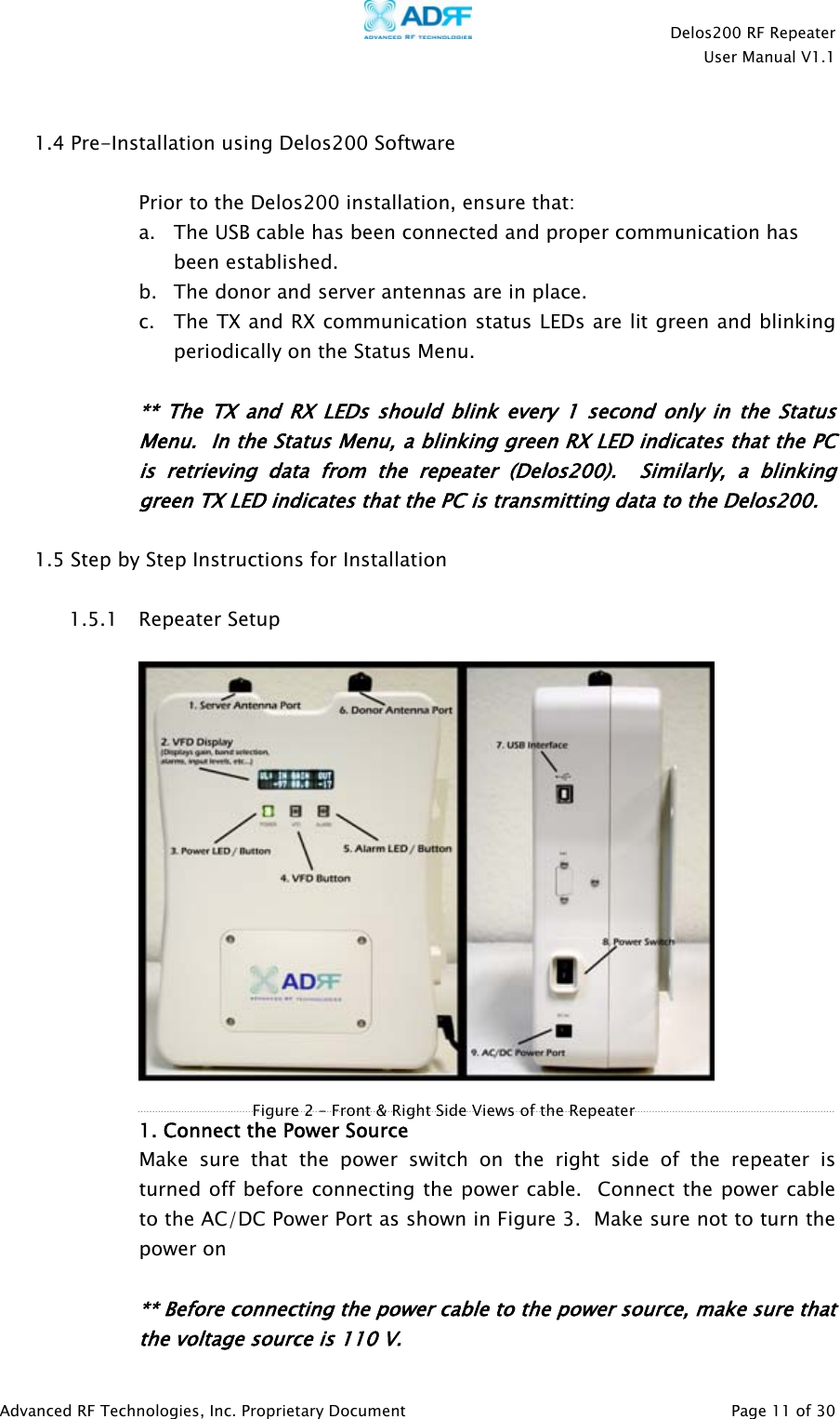
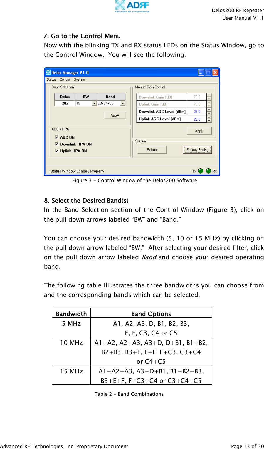
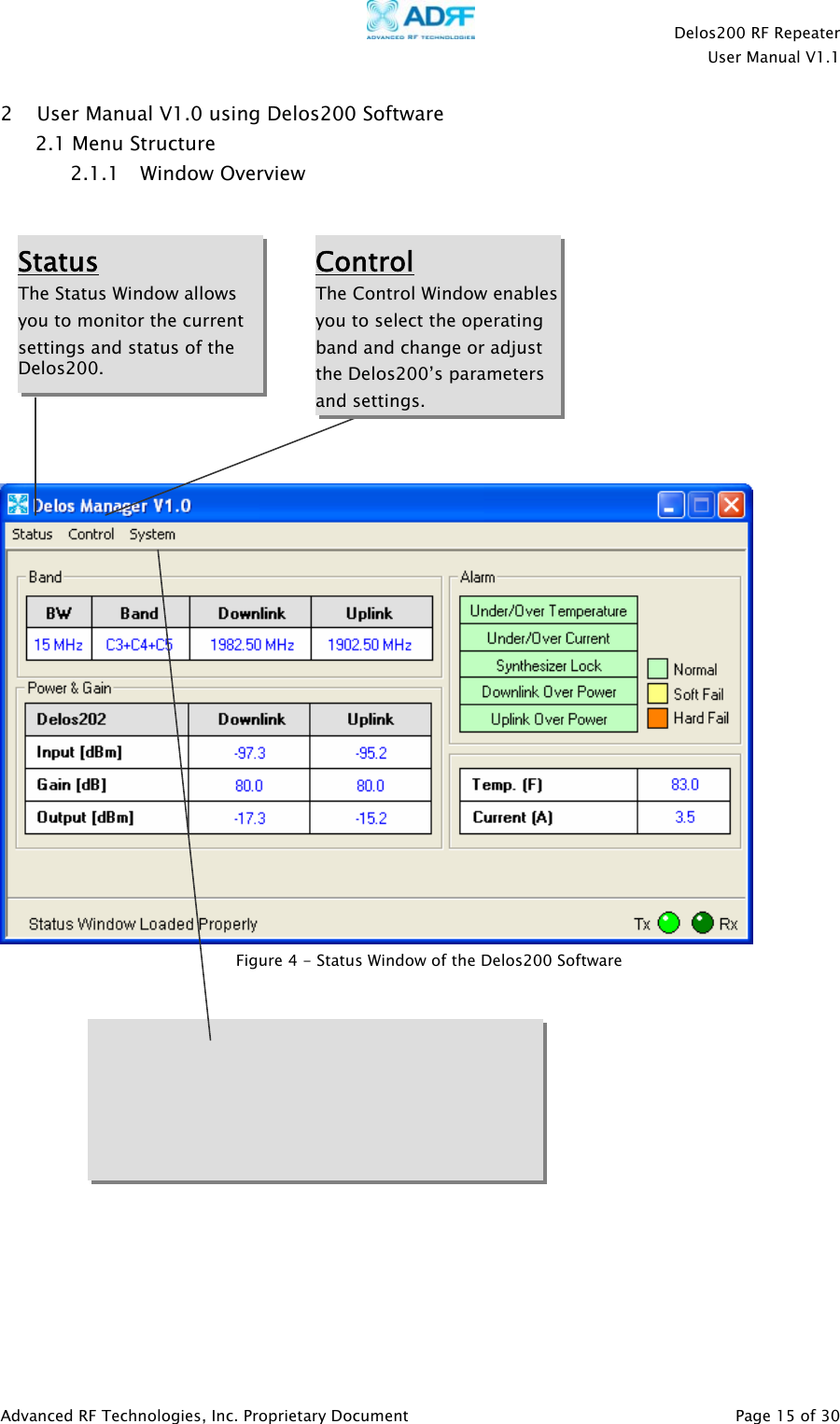
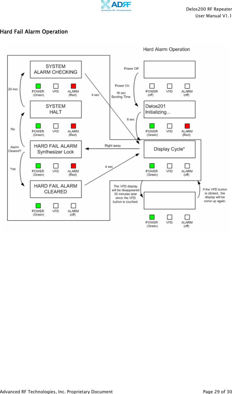
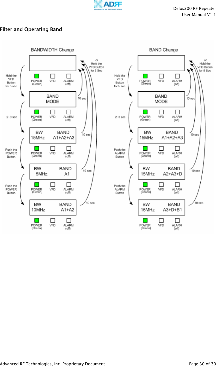
![Delos200 RF Repeater User Manual V1.1 Advanced RF Technologies, Inc. Proprietary Document Page 16 of 30 2.1.2 Status Menu The Status Window is the monitoring window of the Delos200 Software. This window enables the user to monitor the status and settings of the Delos200. In other words, no parameters can be changed in the Status Window. To change parameters, you will need to go to the Control Window. Bands Currently selected band(s) are highlighted. Repeater Input Indicates input signal strength of the repeater after the donor antenna [in dBm]. Repeater Output The output of the repeater [in dBm] before being radiated by the server antenna. Repeater Gain Indicates the gain of the repeater [in dB]. Status Bar Displays the status of the repeater (e.g. Status Window Loaded Properly, etc.), transmit (TX) and receive (RX) communication LEDs. Figure 5 - Status Window of the Delos200 Software Bandwidth Indicates the bandwidth of the selected filter. Downlink/Uplink Indicates currently selected operating frequencies. Alarm Indicates what type of alarm the repeater currently is in. Temp. & Current Indicates what the temperature is inside the repeater and how much current is being drawn.](https://usermanual.wiki/Advanced-RF-Technologies/DELOS201/User-Guide-923060-Page-16.png)