Advanced RF Technologies DELOS201 Delos201 and Delos201 with 5, 10 and 15 MHz filter User Manual manual
Advanced RF Technologies, Inc. Delos201 and Delos201 with 5, 10 and 15 MHz filter manual
manual

DELOS200
USER MANUAL
Version 1.1
2607 Colorado Blvd.
Los Angeles, CA 90041
USA
Tel: 323-254-8131
Fax: 323-254-4928
www.adrftech.com
Delos200 RF Repeater
User Manual V1.1
Advanced RF Technologies, Inc. Proprietary Document Page 2 of 30
Version 1.1 (Released March 25, 2008)
Information in this document is subject to change without notice.
Advanced RF Technologies, Inc. 1996-2008. All rights reserved.
Please send comments to:
E-Mail: info@adrftech.com
Phone: (323) 254-8131
(800) 313-9345
Fax: (323) 254-4928
Address: Advanced RF Technologies, Inc.
Attention: Technical Publications Department
2607 Colorado Blvd., 1st Floor
Los Angeles, CA 90041
USA
www.adrftech.com
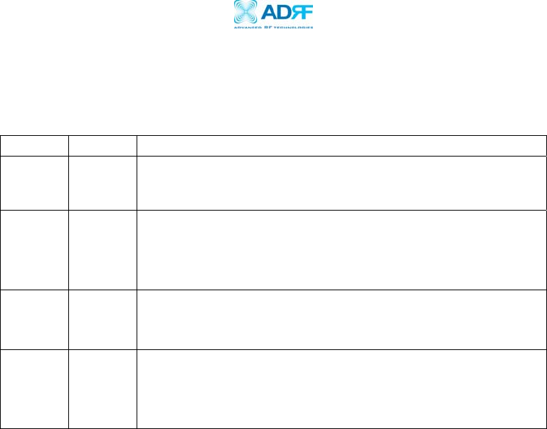
Revision History
Version Author Description Date
1.0 Peter Son June 24, 2006
1.1 Namchul Lee March 25, 2008

Delos200 RF Repeater
User Manual V1.1
Advanced RF Technologies, Inc. Proprietary Document Page 3 of 30
TABLE OF CONTENTS
1. Introduction of Delos200....................................................................................5
1.1 Overview ......................................................................................................5
1.1.1 Highlights ......................................................................................5
1.1.2 Special Features..............................................................................5
1.1.3 Available Models ............................................................................7
1.2 Warnings and Hazards ..................................................................................8
1.3 Delos200 Parts List.....................................................................................10
1.4 Delos200 Software Installation and Requirements.......................................10
1.4.1 Minimum PCS Requirements ....................................................................10
1.4.2 Delos200 Software Installation ................................................................10
** Refer to the Software & USB Driver Setup Guide
............................................10
** Refer to
the Software & USB Driver Setup Guide
............................................10
1.5 Pre-Installation using Delos200 Software....................................................11
1.6 Step by Step Instructions for Installation .....................................................11
1.6.1 Repeater Setup .............................................................................11
2 User Manual V1.0 using Delos200 Software ..................................................15
2.1 Menu Structure ...........................................................................................15
2.1.1 Window Overview .........................................................................15
2.1.2 Status Menu .................................................................................16
2.1.3 Control Menu ...............................................................................17
** You will lose your current saved settings once you click on
Factory Setting.
............................................................................18
2.1.4 System Menu................................................................................19
2.1.4.1 Info. Window ..................................................................19
2.1.4.2 Upgrade Window ............................................................20
2.2 Default Control Settings..............................................................................20
3 Maintenance Guide for Delos200 ..................................................................21
3.1 Periodic Inspection Checklist ......................................................................21
3.2 Preventive Measures for Optimal Operation.................................................21
3.2.1 Recommendations ........................................................................21
• Perform the
Periodic Inspection Checklist
quarterly or
semiannually. ...............................................................................21
3.2.2 Precautions ..................................................................................21
4 Troubleshooting ...........................................................................................22
4.1 Tx & Rx LEDs..............................................................................................22
4.2 Common Installation Problems ...................................................................23
5 Warranty and Repair Policy............................................................................23
5.1 General Warranty ........................................................................................23
5.2 Limitations of Warranty...............................................................................23
Appendix A: Specifications ..........................................................................................25

Delos200 RF Repeater
User Manual V1.1
Advanced RF Technologies, Inc. Proprietary Document Page 4 of 30
Appendix B: Button Operation......................................................................................27
Delos200 RF Repeater
User Manual V1.1
Advanced RF Technologies, Inc. Proprietary Document Page 5 of 30
1. Introduction of Delos200
1.1 Overview
Delos200 series repeaters enhance in-building wireless coverage in the most
effective and cost efficient way. For its intelligent design and versatility,
Delos200 series repeaters are the ideal choice for wireless coverage problems
indoors. Delos200 series repeaters can be used as a stand-alone repeater
with passive antennas connected to it or it can also be used as a feeder repeater
to a DAS (Distributed Antenna System).
1.1.1 Highlights
• 23 dBm Composite Output Power
• 80 dB gain
• 25 dB AGC Range @ 0.5 dB Step
• Can Set AGC Output Power Level
• Auto Level Control Feature
• Band/Channel Selectable via Software/Button
• Three Sliding Filters Built-In (5, 10 & 15 MHz)
1.1.2 Special Features
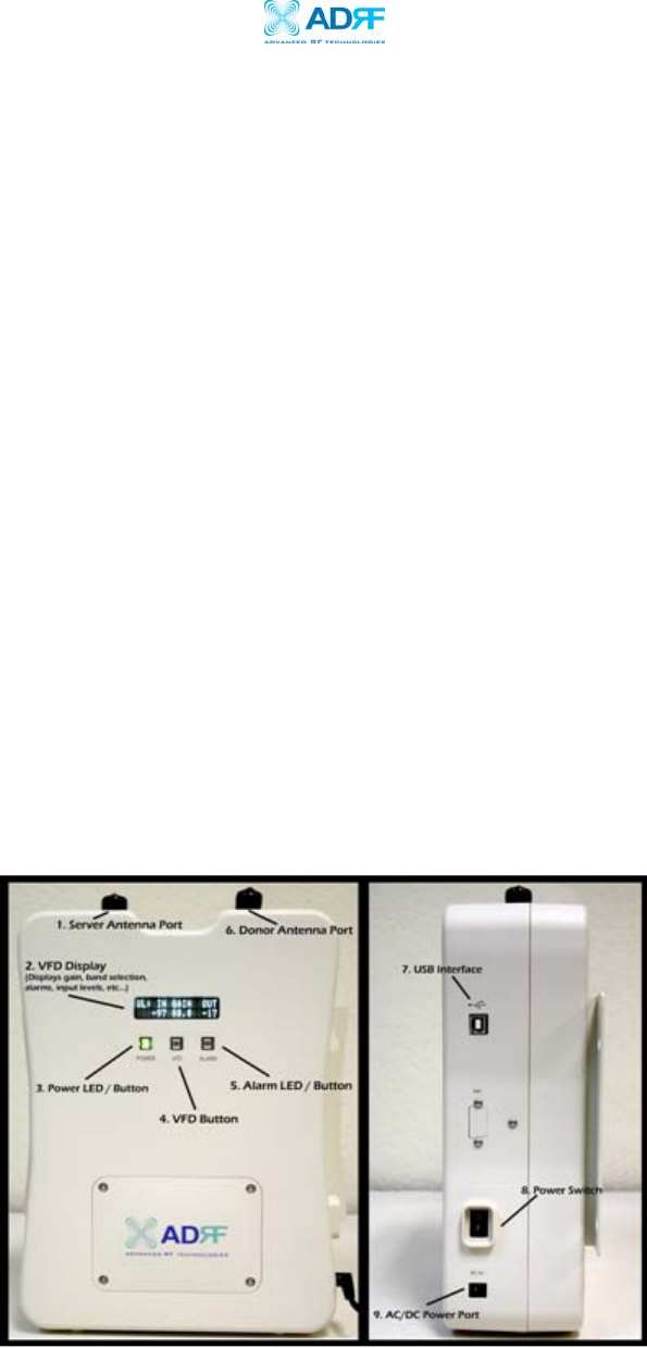
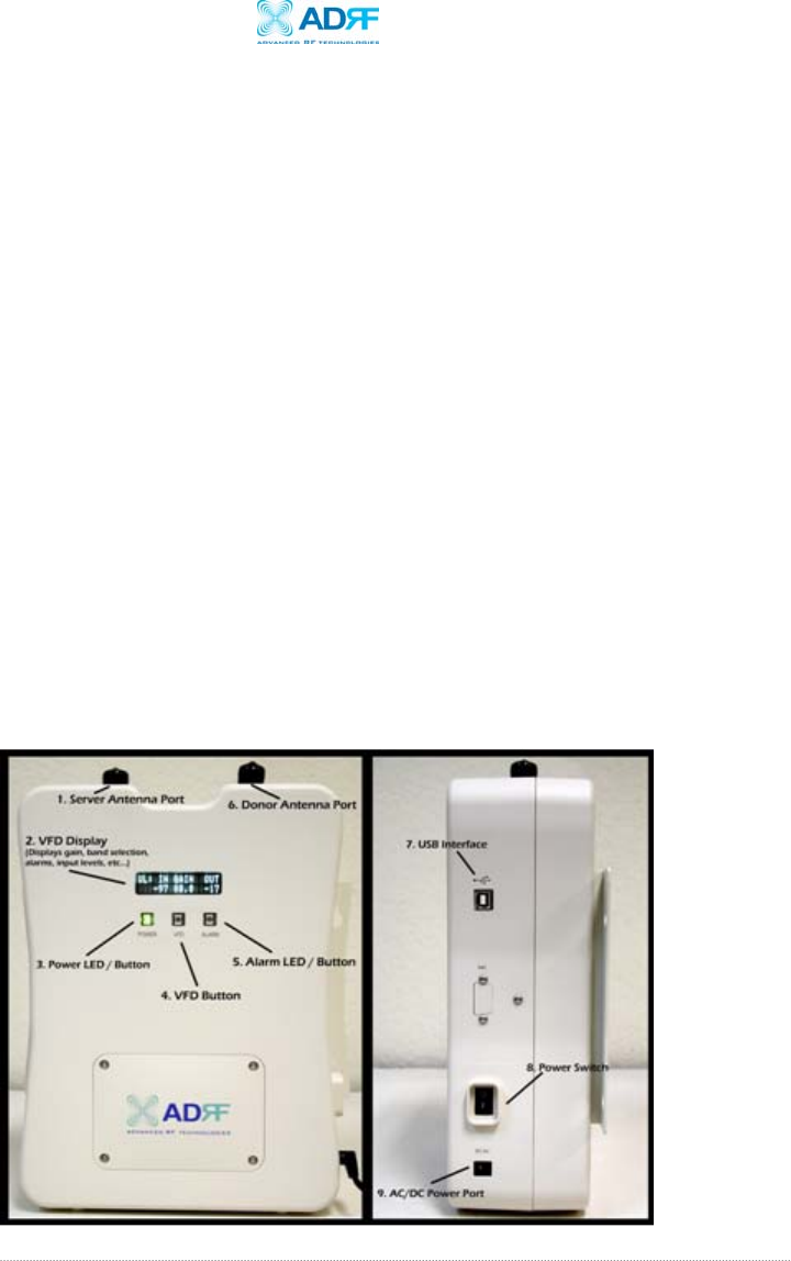
Figure 1 – Front & Right Side Views of the Repeater

Delos200 RF Repeater
User Manual V1.1
Advanced RF Technologies, Inc. Proprietary Document Page 6 of 30
1. Server Antenna Port
One end of the coax cable will connect to the “Server Antenna Port” of
Delos200 while the other end of the cable will connect to the server
antenna which is pointing towards the intended coverage area.
2. VFD Display
In this display, you are able to view the repeater vitals in each link (e.g.
RSS, Gain, Output Power & Alarms).
** Please refer to Appendix B for more detailed information on how the
VFD button operates.
3. Power LED / Button
The Power LED will be lit Green if the power is turned on and will be not
lit if the power is turned off.
At the same time, by pressing the “Power LED” button, you can choose the
desired filer (5, 10 or 15 MHz).
** Please refer to Appendix B for more detailed information on how the
Power LED button operates.
4. VFD Button
By pressing the VFD button, you can see the repeater vitals on the VFD
display. The VFD display will be lit for 30 minutes and will then turn off.
It needs to be pressed again to display the repeater parameters on the
VFD display.
5. Alarm LED / Button
If there’s an alarm, the Alarm LED will be lit Red and will not be lit if there
isn’t any alarm.
At the same time, by pressing the “Alarm LED” button, you can choose the
desired operating band(s). By clicking on the “ALARM LED” button each
time, you will be sliding the filter (5, 10 or 15 MHz) to the right side of
the spectrum by an increment of 5 MHz bandwidth.
** Please refer to Appendix B for more detailed information on how the
Alarm LED button operates.

Delos200 RF Repeater
User Manual V1.1
Advanced RF Technologies, Inc. Proprietary Document Page 7 of 30
6. Donor Antenna Port
One end of the coax cable will connect to the “Donor Antenna Port” of
Delos200 while the other end of the cable will connect to the donor
antenna which is pointing towards the BTS.
The coax cable coming in from the donor antenna (pointing towards the
BTS)
7. USB Interface
For management and troubleshooting purposes, you can connect your PC
to Delos200 Manager via USB cable.
8. Power Switch
To turn the Delos200, you need to turn the power switch on.
9. AC/DC Power Port
To power the repeater, you need to connect the power supply to this port.
1.1.3 Available Models
Delos200 is available in all 1900 MHz PCS band combinations. The
following table illustrates the two standard models:
Product ID Description
Delos201
RF repeater with built-in sliding filters (5, 10
& 15 MHz ) @ 5 MHz increments across the
first 45 MHz PCS spectrum
(DL: 1930-1975 / UL: 1850-1895)
Delos202
RF repeater with built-in sliding filters (5, 10
& 15 MHz) @ 5 MHz increments across the
last 45 MHz PCS spectrum
(DL: 1945-1990 / UL: 1865-1910)
Table 1 – Delos200 Models
Delos200 RF Repeater
User Manual V1.1
Advanced RF Technologies, Inc. Proprietary Document Page 8 of 30
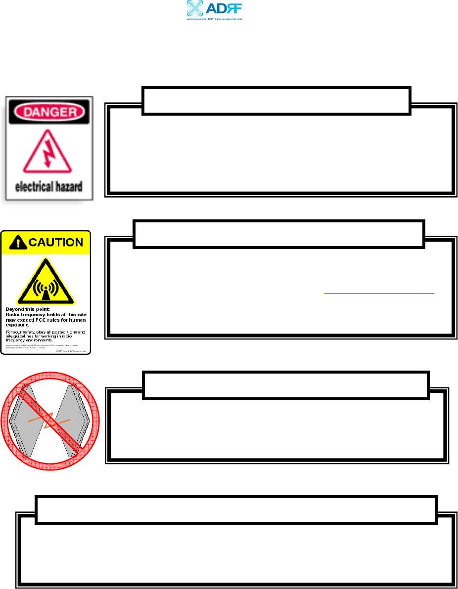
1.2 Warnings and Hazards
Please maintain a safe distance of 20 cm while operating near the donor and the
server antennas. Also, the donor antenna needs to be mounted outdoors on a
permanent structure.
RF EXPOSURE & ANTENNA PLACEMENT Guidelines
Operating the Delos200 with antennas in very close proximity
facing each other could lead to severe damage to the repeater.
WARNING! DAMAGE TO REPEATER
Working with the repeater while in operation, may expose the
technician to RF electromagnetic fields that exceed FCC rules for
human exposure. Visit the FCC website at www.fcc.gov/oet/rfsafety
to learn more about the effects of exposure to RF electromagnetic
fields.
WARNING! EXPOSURE TO RF
Opening the Delos200 could result in electric shock and may cause
severe injury.
WARNING! ELECTRIC SHOCK
Delos200 RF Repeater
User Manual V1.1
Advanced RF Technologies, Inc. Proprietary Document Page 9 of 30
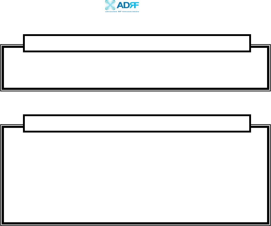
NOTE: This equipment has been tested and found to comply with the limits for a Class
A digital device, pursuant to part 15 of the FCC Rules. These limits are designed to
provide reasonable protection against harmful interference when the equipment is
operated in a commercial environment. This equipment generates, uses, and can
radiate radio frequency energy and, if not installed and used in accordance with the
instruction manual, may cause harmful interference to radio communications.
Operation of this equipment in a residential area is likely to cause harmful
interference in which case the user will be required to correct the interference at his
own expense.
FCC Part 15 Class A
Opening or tampering the Delos200 will void all warranties.
WARRANTY

Delos200 RF Repeater
User Manual V1.1
Advanced RF Technologies, Inc. Proprietary Document Page 10 of 30
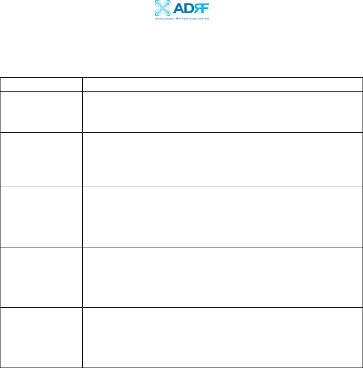
Delos200 Parts List
The Delos200 repeater system includes:
PART ID
QUANTITY
a. Delos200 Repeater Delos20X 1
b. Screws SC01 4
c. **CD Delos200 Manager 1
d. USB Cable USB01 1
e. Power Cable PWRC01 1
** CD includes: (1) GUI Software; (2) User Manual; (3) Delos200 Quick Start
Guide; & (4) Software & USB Driver Setup Guide.
1.3 Delos200 Software Installation and Requirements
1.4.1 Minimum PCS Requirements
CPU: 200 MHz
Memory: 32 MB
Hard Disk: 10 MB (Free Space)
USB Port: 1 USB Port
CD-ROM Drive
Compatible Operating System:
Microsoft Windows 2000 / XP
1.4.2 Delos200 Software Installation
** Refer to the Software & USB Driver Setup Guide
1.4.3 Initial Startup of Delos200 Software
a. Using the USB cable (USB01) that is provided, connect one end of the
cable to the USB port to the PC and the other end to the repeater’s
USB port located on the right side of the repeater.
b. Launch the Delos200 Software.
** Refer to
the Software & USB Driver Setup Guide
Delos200 RF Repeater
User Manual V1.1
Advanced RF Technologies, Inc. Proprietary Document Page 11 of 30
1.4 Pre-Installation using Delos200 Software
Prior to the Delos200 installation, ensure that:
a. The USB cable has been connected and proper communication has
been established.
b. The donor and server antennas are in place.
c. The TX and RX communication status LEDs are lit green and blinking
periodically on the Status Menu.
** The TX and RX LEDs should blink every 1 second only in the Status
Menu. In the Status Menu, a blinking green RX LED indicates that the PC
is retrieving data from the repeater (Delos200). Similarly, a blinking
green TX LED indicates that the PC is transmitting data to the Delos200.
1.5 Step by Step Instructions for Installation
1.5.1 Repeater Setup
1. Connect the Power Source
Make sure that the power switch on the right side of the repeater is
turned off before connecting the power cable. Connect the power cable
to the AC/DC Power Port as shown in Figure 3. Make sure not to turn the
power on
** Before connecting the power cable to the power source, make sure that
the voltage source is 110 V.
Figure 2 – Front & Right Side Views of the Repeater

Delos200 RF Repeater
User Manual V1.1
Advanced RF Technologies, Inc. Proprietary Document Page 12 of 30
2. Connect the Donor Antenna
Connect one end of the RF coaxial cable to the donor antenna and the
other end to the repeater Donor Antenna Port located on the top of the
Delos200 as shown in Figure 2.
3. Connect the Server Antenna
Connect one end of the RF coaxial cable to the server antenna and
connect the other end to the repeater Server Antenna Port located on the
top of the Delos200 as shown in Figure 2.
4. Connect the USB Cable
Using the USB cable (included in the box), connect one end of the cable to
the Delos200’s USB port located on the right side of the repeater and the
other end to the PC’s USB port as shown in Figure 2.
** Install the USB driver and the Delos200 Manager Software prior to
installation.
5. Turn On the Power for Delos200
Make sure that the donor and server antennas and the power cable are
securely connected to the correct ports. Turn the power switch on,
located on the right side of the repeater.
6. Launch the Delos200 Software
Open the Delos200 Software. You will see the Status Menu.
** For more detailed information on the Delos200 Software, please refer
to Section 2 on page 15.
** If only one or both of the LEDs on the Status Window are not blinking:
(1) check the physical USB cable connection or (2) check if the repeater
power is turned on.
Delos200 RF Repeater
User Manual V1.1
Advanced RF Technologies, Inc. Proprietary Document Page 13 of 30
7. Go to the Control Menu
Now with the blinking TX and RX status LEDs on the Status Window, go to
the Control Window. You will see the following:
8. Select the Desired Band(s)
In the Band Selection section of the Control Window (Figure 3), click on
the pull down arrows labeled “BW” and “Band.”
You can choose your desired bandwidth (5, 10 or 15 MHz) by clicking on
the pull down arrow labeled “BW.” After selecting your desired filter, click
on the pull down arrow labeled
Band
and choose your desired operating
band.
The following table illustrates the three bandwidths you can choose from
and the corresponding bands which can be selected:
Bandwidth Band Options
5 MHz A1, A2, A3, D, B1, B2, B3,
E, F, C3, C4 or C5
10 MHz A1+A2, A2+A3, A3+D, D+B1, B1+B2,
B2+B3, B3+E, E+F, F+C3, C3+C4
or C4+C5
15 MHz A1+A2+A3, A3+D+B1, B1+B2+B3,
B3+E+F, F+C3+C4 or C3+C4+C5
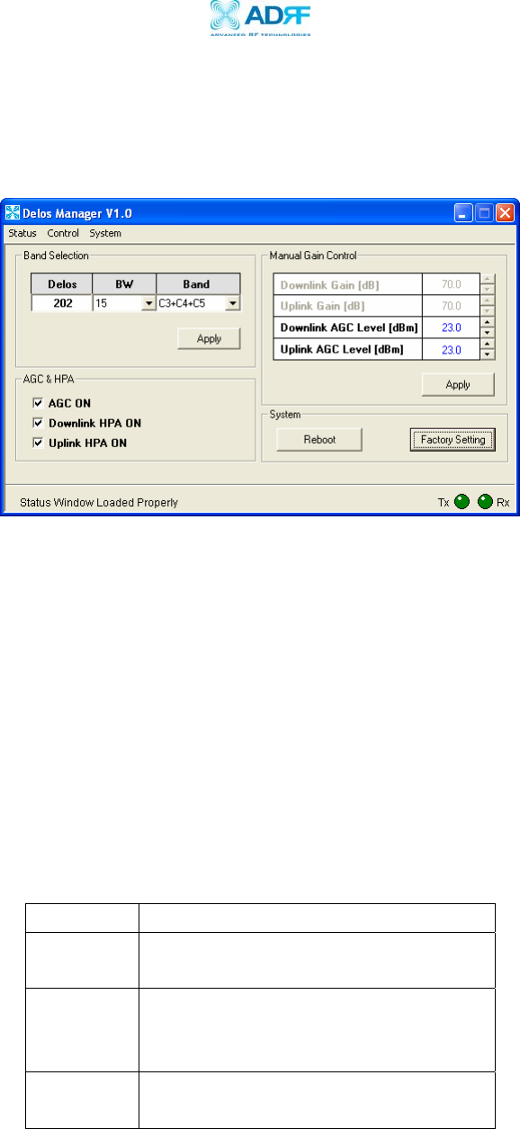
Figure 3 - Control Window of the Delos200 Software
Table 2 – Band Combinations
Delos200 RF Repeater
User Manual V1.1
Advanced RF Technologies, Inc. Proprietary Document Page 14 of 30
** Depending on which model of Delos200 is being used, the band
options will vary. Delos201 doesn’t support the C band while the
Delos202 model doesn’t support the A band.
9. Check the Front LED Panel
Check that the Power LED is on (Green) and the Alarm LED (Red) is off.
** If the Alarm LED is on, refer to Section 2.3 on page 25.
** You can go to the Status Menu of the Delos200 Software to view the
basic parameters of the repeater once the repeater has installed
successfully.
CONGRATULATIONS!!
The Delos200 Installation Process is Complete.
Delos200 RF Repeater
User Manual V1.1
Advanced RF Technologies, Inc. Proprietary Document Page 15 of 30
2 User Manual V1.0 using Delos200 Software
2.1 Menu Structure
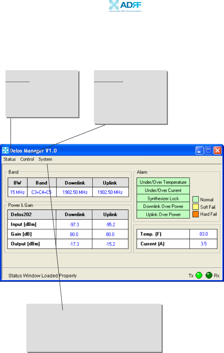
2.1.1 Window Overview
Status
The Status Window allows
you to monitor the current
settings and status of the
Delos200.
Control
The Control Window enables
you to select the operating
band and change or adjust
the Delos200’s parameters
and settings.
Figure 4 - Status Window of the Delos200 Software
Delos200 RF Repeater
User Manual V1.1
Advanced RF Technologies, Inc. Proprietary Document Page 16 of 30
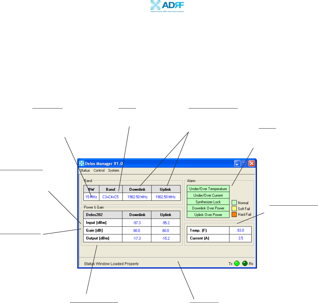
2.1.2 Status Menu
The Status Window is the monitoring window of the Delos200 Software.
This window enables the user to monitor the status and settings of the
Delos200. In other words, no parameters can be changed in the Status
Window. To change parameters, you will need to go to the Control
Window.
Bands
Currently selected
band(s) are highlighted.
Repeater Input
Indicates input
signal strength of
the repeater after
the donor antenna
[in dBm].
Repeater Output
The output of the
repeater [in dBm]
before being radiated
by the server antenna.
Repeater Gain
Indicates the gain
of the repeater
[in dB].
Status Bar
Displays the status of the repeater (e.g. Status
Window Loaded Properly, etc.), transmit (TX)
and receive (RX) communication LEDs.
Figure 5 - Status Window of the Delos200 Software
Bandwidth
Indicates the bandwidth of
the selected filter.
Downlink/Uplink
Indicates currently
selected operating
frequencies. Alarm
Indicates what type of
alarm the repeater
currently is in.
Temp. & Current
Indicates what the
temperature is inside the
repeater and how much
current is being drawn.
Delos200 RF Repeater
User Manual V1.1
Advanced RF Technologies, Inc. Proprietary Document Page 17 of 30
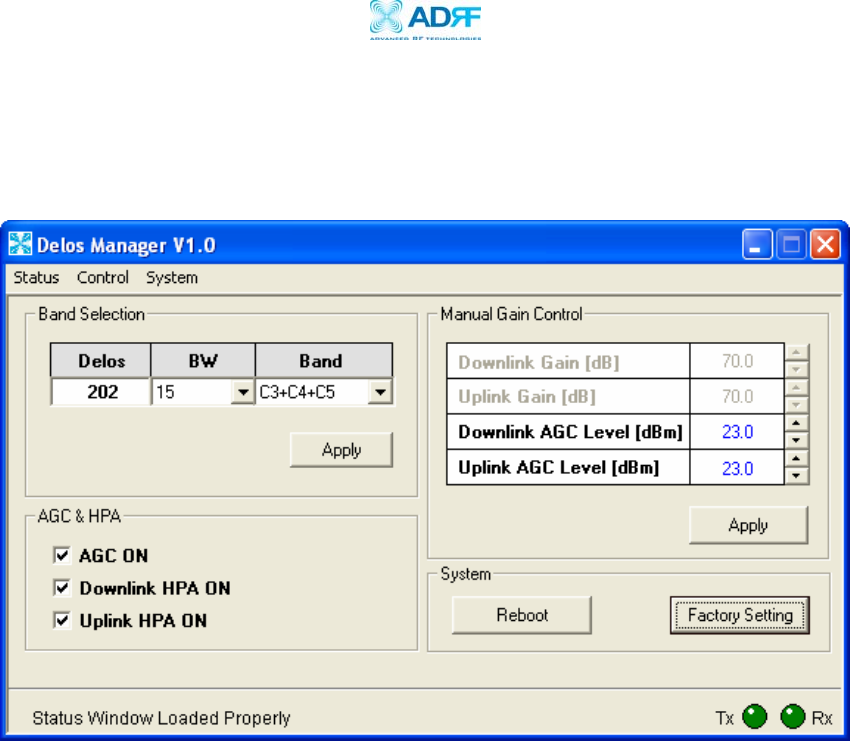
2.1.3 Control Menu
The Control Window lets the user to change parameters of the repeater.
Band Selection
Depending on which model of the Delos200 you have, you can choose the
desired filter from the drop down menu by clicking on
BW
and the corresponding
band options can be viewed by clicking on
Band
. Please refer to Table 2 on page
12 for all the possible band combinations.
AGC Mode
AGC (Auto Gain Control) adjusts the variable gain of the repeater to ensure a
constant specified output power of 23 dBm. The functionality of the AGC feature
is assured under the condition that the input BTS signal is within the specified
AGC range (-57 to -32 dBm => assuming AGC Level is set to 23 dBm) and that
sufficient isolation exists between antennas (≥ 93 dB). By default, the
AGC ON
box is checked. To manually change the gains in both the links,
AGC ON
must
be unchecked.
The user can specify the AGC level in the downlink and in the uplink respectively
@ 0.5 dB step (0 to 23 dBm). By default, the AGC Level is set to 23 dBm in each
link.
Figure 6 - Control Window of the Delos200 Software

Delos200 RF Repeater
User Manual V1.1
Advanced RF Technologies, Inc. Proprietary Document Page 18 of 30
Downlink/Uplink HPA Mode
The HPA mode enables the user to turn the HPA on or off. If the HPA is turned
off on either link, the Delos200 will not operate properly. Both HPAs needs to be
turned on for the RF portion of the repeater to work in both directions (downlink
and uplink). By default, the
Downlink/Uplink HPA ON
box are checked.
Either or both HPAs can be turned off for troubleshooting purposes during an
installation process.
Downlink/Uplink Gain
The gain of the Delos200 is the ratio of the input signal to the output signal.
The gain may be set in both links.
** The manual gain option is disabled when the AGC ON box is checked.
Reboot
By clicking the “Reboot” button, similar to how the operation works in a PC, the
control board of the repeater will restart itself.
Factory Setting
Clicking on the “Factory Setting”
button resets the settings of the repeater to the
original default factory settings as noted in the “Default Control Settings” in
Section 2.4 on page 28.
** You will lose your current saved settings once you click on Factory Setting.
Delos200 RF Repeater
User Manual V1.1
Advanced RF Technologies, Inc. Proprietary Document Page 19 of 30
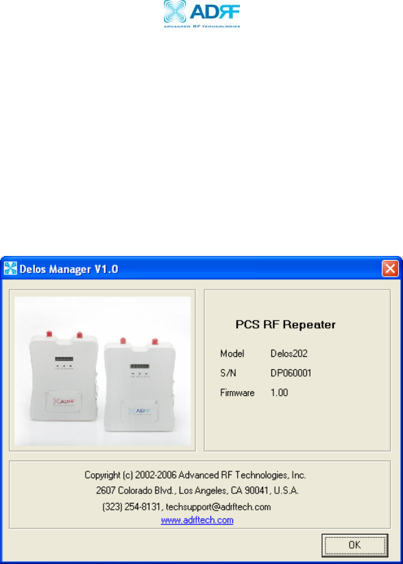
2.1.4 System Menu
2.1.4.1 Info. Window
The Info. Window displays the Model Number, Serial Number and Firmware
Version of the Delos200 repeater. Contact information is included along with
a link to Advanced RF Technologies, Inc.’s URL.
Figure 7 - Info. Window of the Delos200 Software
Delos200 RF Repeater
User Manual V1.1
Advanced RF Technologies, Inc. Proprietary Document Page 20 of 30
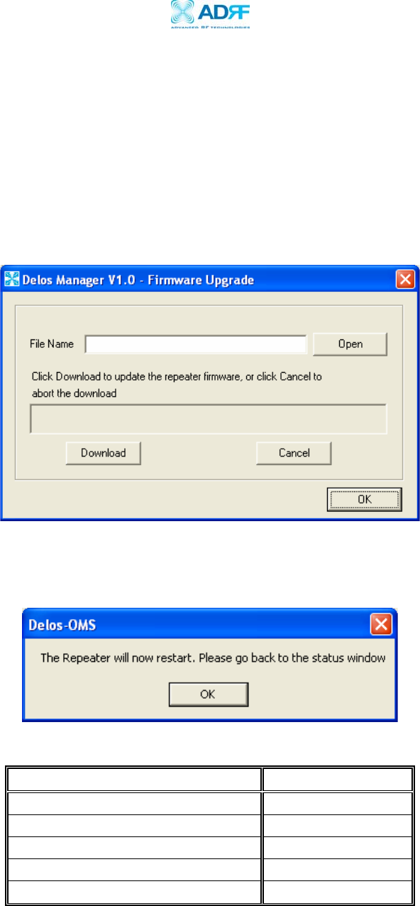
2.1.4.2 Upgrade Window
In order to download the latest repeater firmware, click on the Upgrade
Window. The firmware file will be provided by the technical support group
from Advanced RF Technologies, Inc. Once the firmware file has been saved
on the PC, you would connect the Delos200 repeater to the PC via the USB
cable provided. Click on “Open” and locate the firmware file and click on
‘Download.”
Once the firmware has been downloaded successfully, the following pop-up
window will appear.
2.2 Default Control Settings
Control Item Setting Value
AGC Mode ON
Downlink/Uplink HPA Mode ON
Uplink Tracking Mode ON
Downlink/Uplink Gain 70 dB
Downlink/Uplink AGC Level 23 dBm
** When
AGC ON
mode
is enabled, by default, the
Downlink/Uplink AGC
Level
is set to 23 dBm.
Table 3 - Default Repeater Settings
Figure 8 - Upgrade Window of the Delos200 Software

Delos200 RF Repeater
User Manual V1.1
Advanced RF Technologies, Inc. Proprietary Document Page 21 of 30
3 Maintenance Guide for Delos200
3.1 Periodic Inspection Checklist
a. Check for loose connections to the repeater and antennas. If connections
are loose, make sure that all connections are tightly fastened properly.
b. Cables and connectors are in good condition.
c. Ensure that the repeater brackets are in good condition and that the
repeater is securely fastened.
3.2 Preventive Measures for Optimal Operation
3.2.1 Recommendations
• Perform the
Periodic Inspection Checklist
quarterly or semiannually.
3.2.2 Precautions
• Do not operate the repeater with the antennas in extremely close
proximity as this may cause damage to the repeater.
• Do not change parameters unless instructed to do so by an authorized
supervisor.
• Do not move the repeater unless instructed to do so by an authorized
supervisor.
• Do not detach any cables to the repeater unless repair of respective
components are necessary.
Delos200 RF Repeater
User Manual V1.1
Advanced RF Technologies, Inc. Proprietary Document Page 22 of 30
4 Troubleshooting
4.1 Tx & Rx LEDs
Tx Rx Explanation
Blinking
GREEN
Blinking
GREEN
Successful Connection. The Delos200 Software and the
repeater are communicating successfully.
Blinking
GREEN
Solid
GREEN
The repeater is not receiving any commands from the
software. In this state, the repeater is either processing or
executing a command. Wait for a few seconds for the Rx LED
to blink periodically.
Blinking
GREEN RED
The repeater is not receiving any commands from the
software. Ensure that the repeater is tuned on and check for
proper USB port connection.
RED RED
The USB port can not send or receive data. Check if the USB
driver has been installed and also verify if the physical
connection on both ends of the USB cable is secure. Ensure
that the repeater is turned on.
** The Tx/Rx LEDs will blink periodically only on the Status Window.
Table 4 - Tx and Rx LEDs
Delos200 RF Repeater
User Manual V1.1
Advanced RF Technologies, Inc. Proprietary Document Page 23 of 30
4.2 Common Installation Problems
Problem Possible Solution
USB port is
not being
recognized
You would need to install the driver for the USB cable which can be
found with the CD that comes with the repeater.
The power
green LED on
the front panel
is not lit.
Check if the power switch is turned on. Also verify if the power cord is
securely connected to the repeater. Make sure there’s no power
outage.
GUI Software &
Laptop - No
Communication
The very first time during installation, once you connect the USB cable
to the repeater and the laptop, the PC will automatically detect a new
hardware has been added in the system and will prompt you to install
the driver which can be found in the CD. The driver needs to be
installed only once.
Status Window –
Weak Signal or
Donor RSS
Check that the donor and server antennas are connected to the proper
antenna ports on the repeater.
Reposition or rotate the donor antenna around until a stronger signal
is received.
Downlink/Uplink
Over Power
Alarm
Add an attenuator after the donor/server antenna to reduce the strong
donor/server signal coming into the repeater.
An oscillation in the system could cause this alarm. Check if there is
sufficient separation between the donor and the server antennas.
5 Warranty and Repair Policy
5.1 General Warranty
The Delos200 carries a Standard Warranty period of two (2) years unless indicated
otherwise on the package or in the acknowledgment of the purchase order.
5.2 Limitations of Warranty
Your exclusive remedy for any defective product is limited to the repair or
replacement of the defective product. Advanced RF Technologies, Inc. may elect
which remedy or combination of remedies to provide in its sole discretion.
Advanced RF Technologies, Inc. shall have a reasonable time after determining that a
defective product exists to repair or replace the problem unit. Advanced RF
Technologies, Inc. warranty applies to repaired or replaced products for the balance
of the applicable period of the original warranty or ninety days from the date of
shipment of a repaired or replaced product, whichever is longer.
Table 5 – Troubleshootin
g
Ti
p
s

Delos200 RF Repeater
User Manual V1.1
Advanced RF Technologies, Inc. Proprietary Document Page 24 of 30
5.3 Limitation of Damages
The liability for any defective product shall in no event exceed the purchase price for
the defective product.
5.4 No Consequential Damages
Advanced RF Technologies, Inc. has no liability for general, consequential, incidental
or special damages.
5.5 Additional Limitation on Warranty
Advanced RF Technologies, Inc. standard warranty does not cover products which
have been received improperly packaged, altered, or physically damaged. For
example, broken warranty seal, labels exhibiting tampering, physically abused
enclosure, broken pins on connectors, any modifications made without Advanced RF
Technologies, Inc. authorization, will void all warranty.
5.6 Return Material Authorization (RMA)
No product may be returned directly to Advanced RF Technologies, Inc. without first
getting an approval from Advanced RF Technologies, Inc. If it is determined that
the product may be defective, you will be given an RMA number and instructions in
how to return the product. An unauthorized return, i.e., one for which an RMA
number has not been issued, will be returned to you at your expense. Authorized
returns are to be shipped to the address on the RMA in an approved shipping
container. You will be given our courier information. It is suggested that the
original box and packaging materials should be kept if an occasion arises where a
defective product needs to be shipped back to Advanced RF Technologies, Inc. To
request an RMA, please call (323) 254-8131 or send an email to
techsupport@adrftech.com.
Delos200 RF Repeater
User Manual V1.1
Advanced RF Technologies, Inc. Proprietary Document Page 25 of 30
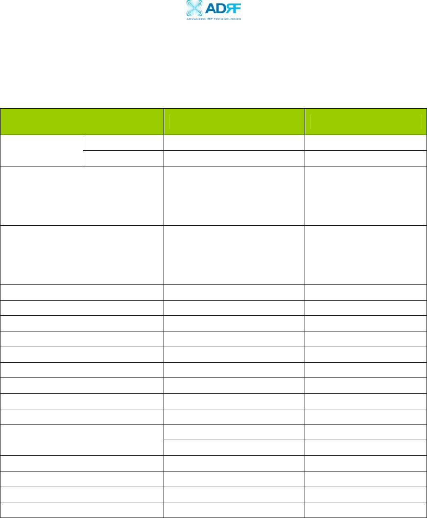
Appendix A: Specifications
ELECTRICAL SPECIFICATIONS
PARAMETERS SPECIFICATIONS COMMENTS
DL 1930 to 1990 MHz Frequency
Range UL 1850 to 1910 MHz
Sub Band Filtering 5/10/15 MHz Sliding Filter
Model 1
DL: 1930-1975 MHZ /
UL: 1850-1895 MHZ
Sub Band Filtering 5/10/15 MHz Sliding Filter
Model 2
DL: 1945-1990 MHZ /
UL: 1865-1910 MHZ
Operating Frequency Programmable Freq. Step: 10 KHz
Frequency Error ≤ +/- 0.1 ppm
Delay ≤ 5 usec Each Direction
Input Dynamic Range -32 to -57 dBm
Repeater Gain 55 to 80 dB
Maximum DL&UL Output Power +23 dBm Composite
DL AGC Range 25 dB / 1 dB Step
UL AGC Range 25 dB / 1 dB Step
Gain Flatness +/- 2.5 dB
≤ -45 dBc @ Fc +/- 885 KHz
In Band Noise ≤ -50 dBc @ Fc +/- 1.98 MHz
Spurious Emission < -13 dBm @ Fc +/- 2.25 MHz
Rho Factor ≥ 0.912
Noise Figure ≤ 5 dB
VSWR ≤ 1.5:1
Delos200 RF Repeater
User Manual V1.1
Advanced RF Technologies, Inc. Proprietary Document Page 26 of 30
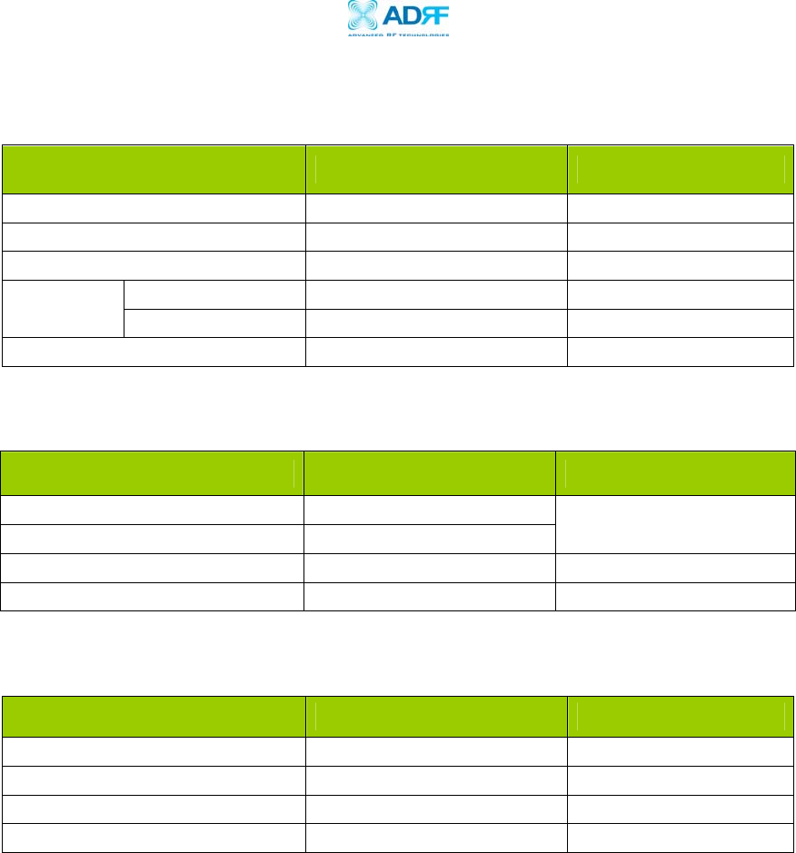
MECHANICAL SPECIFICATIONS
PARAMETERS SPECIFICATIONS COMMENTS
Housing (W x H x D) 8.27 x 11.03 x 3.57 inches
Housing Material Aluminum & Plastic
Weight ≤ 11 lbs
Antenna N-Type (Female) Connector
Type Software Interface USB
Cooling External Convection
POWER SPECIFICATIONS
PARAMETERS SPECIFICATIONS COMMENTS
Main AC Power 100 to 240 VAC
AC Frequency 50 to 60 Hz
Power Adapter complies
with UL & CE
Adaptor Voltage & Current 6 VDC / 4.5 A
Power Consumption ≤ 30 Watts
ENVIRONMENTAL SPECIFICATIONS
PARAMETERS SPECIFICATIONS COMMENTS
Operating Temperature +41 ˚F to +113 ˚F
Storage Temperature +23 ˚F to +176 ˚F
Humidity 10 to 85%, RH
MTBF 75,000 hours
Delos200 RF Repeater
User Manual V1.1
Advanced RF Technologies, Inc. Proprietary Document Page 27 of 30
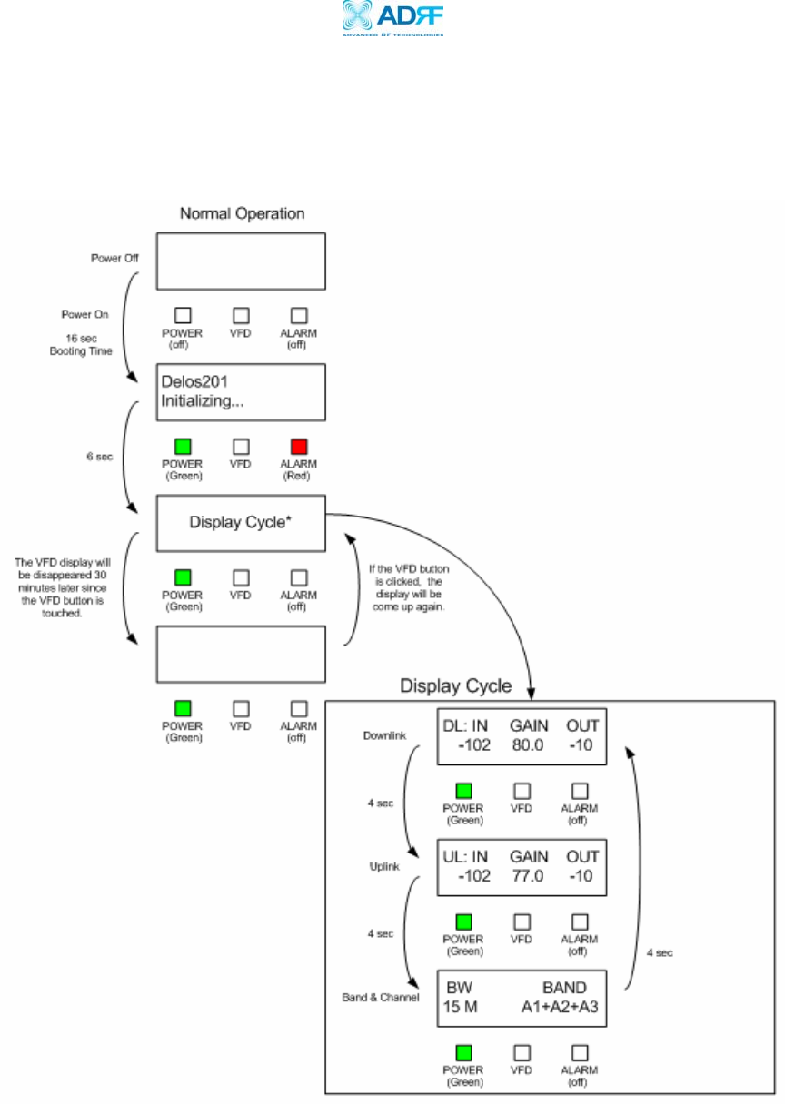
Appendix B: Button Operation
Normal Operation
Delos200 RF Repeater
User Manual V1.1
Advanced RF Technologies, Inc. Proprietary Document Page 28 of 30
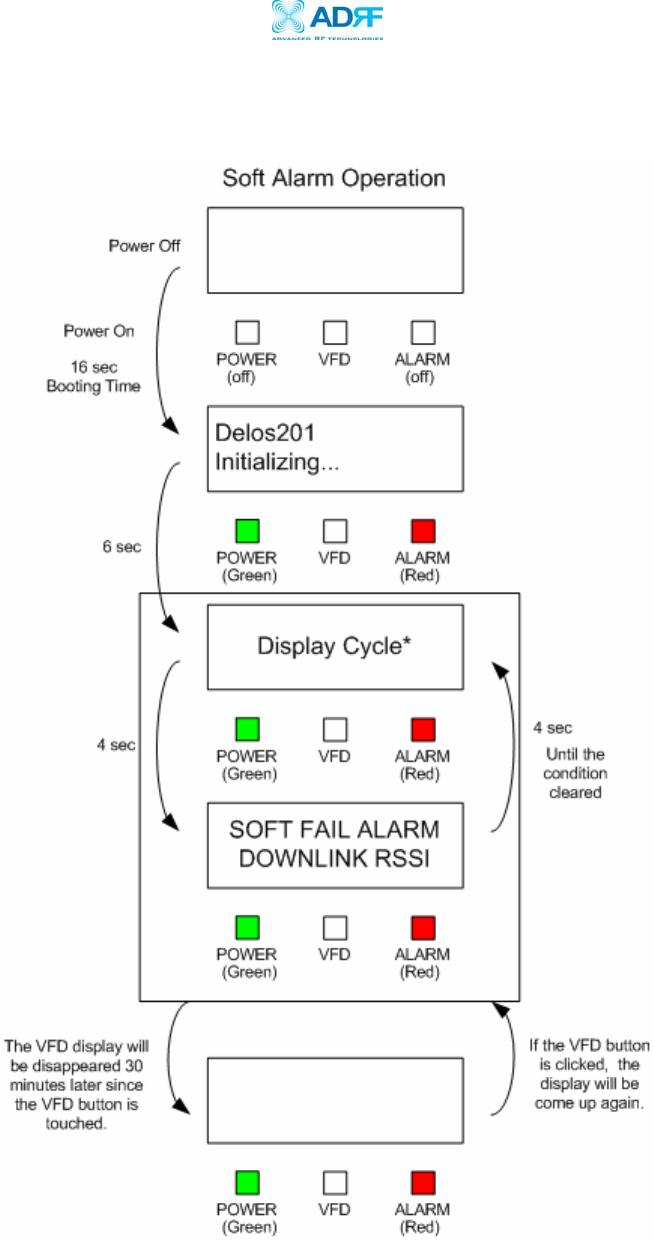
Soft Fail Alarm Operation
Delos200 RF Repeater
User Manual V1.1
Advanced RF Technologies, Inc. Proprietary Document Page 29 of 30
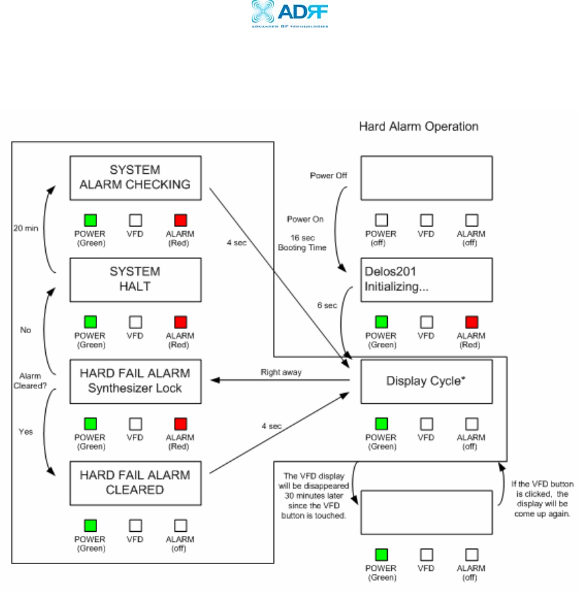
Hard Fail Alarm Operation
Delos200 RF Repeater
User Manual V1.1
Advanced RF Technologies, Inc. Proprietary Document Page 30 of 30
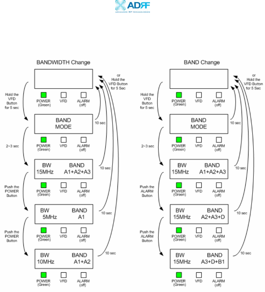
Filter and Operating Band