Advanced RF Technologies EPOCH-HP-20 Epoch-HP-20, Epoch-HP-10, Epoch-HP-05 1900MHz band User Manual Epoch HP
Advanced RF Technologies, Inc. Epoch-HP-20, Epoch-HP-10, Epoch-HP-05 1900MHz band Epoch HP
Contents
- 1. instructions
- 2. manual
manual

EPOCH-HP
USER MANUAL
Version 1.1

Epoch-HP RF Repeater
User Manual V1.1
Advanced RF Technologies, Inc. Proprietary Document Page 2 of 36
Version 1.1 (Modified May 4, 2007)
Information in this document is subject to change without notice.
Advanced RF Technologies, Inc. 1996-2007. All rights reserved.
Changes or modifications not expressly approved by the party responsible for
compliance could void the user’s authority to operate the equipment.
NOTE: This equipment has been tested and found to comply with the limits for a Class A
digital device, pursuant to part 15 of the FCC Rules. These limits are designed to pro-
vide reasonable protection against harmful interference when the equipment is operated
in a commercial environment. This equipment generates, uses, and can radiate radio
frequency energy and, if not installed and used in accordance with the instruction
manual, may cause harmful interference to radio communications. Operation of this
equipment in a residential area is likely to cause harmful interference in which case the
user will be required to correct the interference at his own expense.
Please send comments to:
E-Mail: info@adrftech.com
Phone: (323) 254-8131
Fax: (323) 254-4928
Address: Advanced RF Technologies, Inc.
Attention: Technical Publications Department
2607 Colorado Blvd., 1st floor
Los Angeles, CA 90041
USA

Epoch-HP RF Repeater
User Manual V1.1
Advanced RF Technologies, Inc. Proprietary Document Page 3 of 36
TABLE OF CONTENTS
1. Introduction of Epoch-HP ...................................................................................5
1.1 Overview ......................................................................................................5
1.1.1 Highlights ......................................................................................5
1.1.2 Available Models ............................................................................5
2. Installation Guide for Epoch-HP..........................................................................6
2.1 Environmental Requirements ........................................................................6
2.1.1 Antenna Separation/Isolation..........................................................6
2.1.2 Line of Sight ...................................................................................8
2.2 Warnings and Hazards ..................................................................................9
2.3 RF exposure warning ....................................................................................9
2.4 Tools and Recommendations for Installation...............................................11
2.5 Epoch-HP Parts List ....................................................................................11
2.6 Epoch-H V1.X Installation and Requirements ..............................................11
2.6.1 Minimum Requirements ..................................................................11
2.6.2 Epoch-H V1.X Installation ...............................................................12
2.6.3 Initial Startup of Epoch-H V1.X........................................................12
2.7 Pre-Installation using Epoch-H V1.X ...........................................................12
2.8 Step by Step Instructions for Installation .....................................................12
2.8.1 Repeater Setup .............................................................................12
3. User Manual V1.0 using Epoch-HP V1. X.......................................................17
3.1 Menu Structure ...........................................................................................17
3.1.1 Window Overview .........................................................................17
3.1.2 Status Window..............................................................................18
3.1.3 Control Menu ...............................................................................19
3.1.3.1 General Setting Window..................................................19
3.1.3.2 Alarm Setting Window ....................................................22
3.1.4 Install Window ..............................................................................23
3.1.5 System Menu................................................................................25
3.1.5.1 Information ....................................................................22
3.1.5.2 Firmware Upgrade ..........................................................22
3.2 Using the Epoch-H V1.X .............................................................................26
3.2.1 Changing Parameters ...................................................................26
3.3 Alarms........................................................................................................27
3.3.1 General (Fixed Parameter) Alarms .................................................28
3.3.2 Downlink/Uplink Alarms...............................................................28
3.4 Default Control Settings..............................................................................29
3.4.1 Default General Setting.................................................................29
3.4.2 Default Alarm Setting ...................................................................29
4. Maintenance Guide for Epoch-HP..................................................................30
4.1 Periodic Inspection Checklist ......................................................................30

Epoch-HP RF Repeater
User Manual V1.1
Advanced RF Technologies, Inc. Proprietary Document Page 4 of 36
4.2 Preventive Measures for Optimal Operation.................................................30
4.2.1 Recommendations ........................................................................30
4.2.2 Precautions ..................................................................................30
5. Troubleshooting ...........................................................................................31
5.1 Epoch-H V1.X Scenarios .............................................................................31
5.2 Common Installation Problems ...................................................................31
6. Warranty and Repair Policy............................................................................33
6.1 General Warranty ........................................................................................33
6.2 Limitations of Warranty...............................................................................33
Appendix A: Specifications ..........................................................................................35
A.1 Repeater Specifications (Epoch-HP-05).......................................................35

Epoch-HP RF Repeater
User Manual V1.1
Advanced RF Technologies, Inc. Proprietary Document Page 5 of 36
1. Introduction of Epoch-HP
1.1 Overview
Epoch-HP series repeaters enhances outdoor wireless coverage in the most
effective and cost efficient way. For its intelligent design and versatility, Epoch-
HP series repeaters are the ideal choice for wireless coverage problems outdoors.
In many large scale in-building applications, Epoch-HP series repeaters can also
be used (e.g. malls, campus, stadiums, etc.) with passive antennas instead of a
DAS (distributed antenna system) and offer significant cost savings.
1.1.1 Highlights
• 37, 40 or 43 dBm Composite Output Power
• 95 dB gain
• 30 dB AGC Range @ 0.5 dB Step
• Can Set AGC Output Power Level
• Band Selectable via Software
• Can Support Non-Contiguous Bands
• Supports Embedded Wireless Modem
• Supports Network Management Monitoring System via SNMP
1.1.2 Available Models
Epoch-HP is available in all 1900 MHz PCS band combinations. The
following table illustrates the six models which are available in the
Epoch-HP series:
Product ID Description
Epoch-HP-05-SX
5 W composite output power with 95 dB of gain (30
dB dynamic AGC range).
Band Option 1 (S1): Any 5 or 15 MHz block or any 5
MHz and 15 MHz contiguous blocks at anytime.
Band Option 2 (S2): Any 5 or 10 MHz block or any 5
MHz and 15 MHz contiguous blocks at anytime.
Band Option 3 (S3): Any 5 or 5 MHz block or any 5
MHz and 15 MHz contiguous blocks at anytime.
Epoch-HP-10-SX 10 W composite output power with 95 dB of gain

Epoch-HP RF Repeater
User Manual V1.1
Advanced RF Technologies, Inc. Proprietary Document Page 6 of 36
(30 dB dynamic AGC range).
Band Option 1 (S1): Any 5 or 15 MHz block or any 5
MHz and 15 MHz contiguous blocks at anytime.
Band Option 2 (S2): Any 5 or 10 MHz block or any 5
MHz and 15 MHz contiguous blocks at anytime.
Band Option 3 (S3): Any 5 or 5 MHz block or any 5
MHz and 15 MHz contiguous blocks at anytime.
Epoch-HP-20-SX
20 W composite output power with 95 dB of gain
(30 dB dynamic AGC range).
Band Option 1 (S1): Any 5 or 15 MHz block or any 5
MHz and 15 MHz contiguous blocks at anytime.
Band Option 2 (S2): Any 5 or 10 MHz block or any 5
MHz and 15 MHz contiguous blocks at anytime.
Band Option 3 (S3): Any 5 or 5 MHz block or any 5
MHz and 15 MHz contiguous blocks at anytime.
** Special band combinations are also supported in all the models.
2. Installation Guide for Epoch-HP
2.1 Environmental Requirements
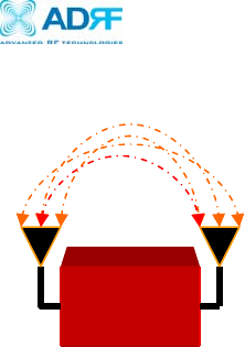
2.1.1 Antenna Separation/Isolation
Separation between antennas is necessary to prevent oscillation.
Oscillation occurs when the signal entering the system continually
reenters, due to the lack of separation between the donor and server
antennas. In other words, the signal is being fed back into the system.
This creates a constant amplification of the same signal. As a result, the
noise level rises above the signal level.
Table 1 – Epoch-HP Models
Epoch-HP RF Repeater
User Manual V1.1
Advanced RF Technologies, Inc. Proprietary Document Page 7 of 36
To prevent feedback, the donor and server antennas must be separated
by an appropriate distance to provide sufficient isolation. Isolation is
attained by separating antennas a sufficient distance so that the output
of one antenna does not reach the input of the other. This distance is
dependent on the gain of the repeater.
A sufficient isolation value is 13 ~ 15 dB greater than the maximum gain
of the repeater. For example, if the gain of the repeater is 50 dB, then an
isolation of 63 ~ 65 dB or greater is required. In the same manner,
because the Epoch-HP has a maximum gain of 95 dB, it requires an
isolation of at least 108 ~ 110 dB.
Donor Server
RF Repeater
Figure 1 - RF Repeater Oscillation
Epoch-HP RF Repeater
User Manual V1.1
Advanced RF Technologies, Inc. Proprietary Document Page 8 of 36
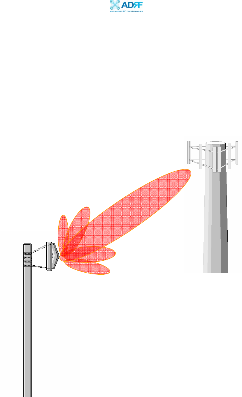
2.1.2 Line of Sight
The donor antenna which points towards the base station typically has a
narrow beam antenna pattern. As a result, a slight deviation away from
the direction of the BTS can lead to less than optimum results. In
addition, obstacles between the repeater and the BTS may impair the
repeater from obtaining any BTS signal. As a result, the repeater cannot
transmit signal to the coverage area. Therefore, a direct line of sight to
the BTS for the donor antenna is vital to the function of a repeater. For
the same reason, placing the server antenna in direct line of sight of the
coverage area is also necessary.
Figure 2 - Direct Line of Sight to the BTS
Donor
Antenna
BTS
Epoch-HP RF Repeater
User Manual V1.1
Advanced RF Technologies, Inc. Proprietary Document Page 9 of 36
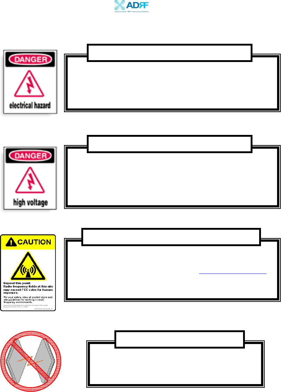
2.2 Warnings and Hazards
Operating the Epoch-HP with antennas in very close
proximity facing each other could lead to severe
damage to the repeater.
WARNING!
Working with the repeater while in operation, may expose the
technician to RF electromagnetic fields that exceed FCC rules for
human exposure. Visit the FCC website at www.fcc.gov/oet/rfsafety
to learn more about the effects of exposure to RF electromagnetic
fields.
WARNING! EXPOSURE TO RF
In installing donor or server antennas, avoid close proximity to
overhead power lines or high power components. Contact with
high power components will severely damage the repeater and may
cause serious injury and/or death to the user. Exercise extreme
caution when installing antennas near high power lines.
WARNING! HIGH VOLTAGE
Tampering with the modules within the Epoch-HP repeater exposes
the user to electric shock and the risk of damaging the unit. DO
NOT TAMPER with modules within the unit. Opening or tampering
with any modules inside the Epoch-HP will void all warranties.
WARNING! ELECTRIC SHOCK

Epoch-HP RF Repeater
User Manual V1.1
Advanced RF Technologies, Inc. Proprietary Document Page 10 of 36
2.3 RF exposure warning
Important Safety Information
In order to satisfy the FCC RF exposure requirements, you must ensure that the
installation complies with following:
For INDOOR use, an omni-directional antenna with a maximum gain of 3 dBi can be
used with this unit. Service antenna is connected to the Server port in the Epoch-HP via
a cable with typical 1~10 dB loss in accordance with the length of the cable.
Service antennas must be positioned to observe minimum separation of 50 cm (~20
inch) from all users and bystanders. For the protection of personnel working in the
vicinity of service antennas, the following guidelines for minimum distances between the
human body and the antenna must be observed.
The installation of an service antenna must be such that, under normal conditions, all
personnel cannot come within 50 cm(~20 inch) from any service antenna. Exceeding this
minimum separation will ensure that the employee or bystander does not receive RF
exposure beyond the maximum permissible exposure according to section 1.1310
(Limits for General Population/Uncontrolled Exposure)
For OUTDOOR use, an directional antenna with a typical gain of 12 dBi can be used with
this unit. Donor antenna is connected to the donor port in the Epoch-HP via a cable with
typical 1~10 dB loss in accordance with the length of the cable.
Donor antenna must be positioned to observe minimum separation of 152 cm (~ 5 ft)
from all users and bystanders. For the protection of personnel working in the vicinity of
service antennas, the following guidelines for minimum distances between the human
body and the antenna must be observed.
The installation of an donor antenna must be such that, under normal conditions, all
personnel cannot come within 152 cm(~5 ft) from donor antenna. Exceeding this
minimum separation will ensure that the employee or bystander does not receive RF
exposure beyond the maximum permissible exposure according to section 1.1310
(Limits for General Population/Uncontrolled Exposure)
!

Epoch-HP RF Repeater
User Manual V1.1
Advanced RF Technologies, Inc. Proprietary Document Page 11 of 36
2.4 Tools and Recommendations for Installation
The following may be necessary (not required) for installation of the repeater:
a. Crescent Wrench
b. Philips Screw Driver
c. Lift, Ladder, or Boom Truck
d. Spectrum Analyzer
e. Sweep Tester
f. Signal Generator
g. Pilot Scanner
h. RF Power Meter
i. Voltmeter
j. Coaxial Cables
k. Compass
l. PC with an USB port
The list above may vary depending on if brackets are used to install the repeater.
Bring additional tools that may be useful during installation. It is recommended
that two people install the Epoch-HP repeater system.
2.5 Epoch-HP Parts List
The Epoch-HP repeater system includes:
PART ID
QUANTITY
a. Epoch-HP Repeater EPOCHHP01 1
b. Nuts and Bolts BLTS01 4
c. Epoch-H V1.X GUI HPOMS01 1
d. Ground Cable GNDSTD01 1
e. USB Cable USB01 1
f. Keys KEYS01 2
2.6 Epoch-H V1.X Installation and Requirements
2.5.1 Minimum Requirements
Hardware (PC Platform)
CPU: 200 MHz
Memory: 32 MB
Hard Disk: 10 MB (Free Space)
USB Port: 1 Port
CD-ROM Drive
Compatible Operating System:
Microsoft Windows XP (Preferred), 2000

Epoch-HP RF Repeater
User Manual V1.1
Advanced RF Technologies, Inc. Proprietary Document Page 12 of 36
2.5.2 Epoch-H V1.X Installation
Installing the Epoch-H V1.X
a. Insert the CD into the CD-ROM drive.
b. Click on “My Computer.”
c. In the “My Computer” window, click on your CD-ROM drive (usually
labeled D:).
d. Double-click the file labeled “Epoch-H V1.x.exe.”
e. The installation wizard will guide you through the conclusion of the
Epoch-H V1.X installation process.
2.5.3 Initial Startup of Epoch-H V1.X
a. Using the USB cable (USB01) that is provided, connect one end of the
cable to the PC USB port and the other end to the repeater’s USB port
located on the bottom of the repeater.
b. Open the Epoch-H V1.X software
2.7 Pre-Installation using Epoch-H V1.X
Prior to the Epoch-HP installation, ensure that:
a. The USB driver is installed and the USB cable is connected at both
ends.
b. The donor and server antennas are in place.
c. The TX and RX communication status LEDs are blinking.
** The TX and RX LEDs should blink every 1 second only in the Status
Window. In the Status Window, a blinking green RX LED indicates that the
PC is retrieving data from the repeater (Epoch-HP). Similarly, a blinking
green TX LED indicates that the PC is transmitting data to the Epoch-HP.
** If neither of the LEDs is blinking: (1) check if the USB deriver has been
installed; (2) check the USB cable is connected properly between the PC
and the repeater; or (3) check if the repeater power is on.
2.8 Step by Step Instructions for Installation
2.8.1 Repeater Setup
Epoch-HP RF Repeater
User Manual V1.1
Advanced RF Technologies, Inc. Proprietary Document Page 13 of 36
1. Open the Epoch-HP
Open the front door of the repeater cabinet by using the key (KEYS01)
provided. There are two locks integrated into the door latches. One key
works for both locks.
** Please keep the cabinet door open fully during the installation until
you are instructed to close the cabinet.
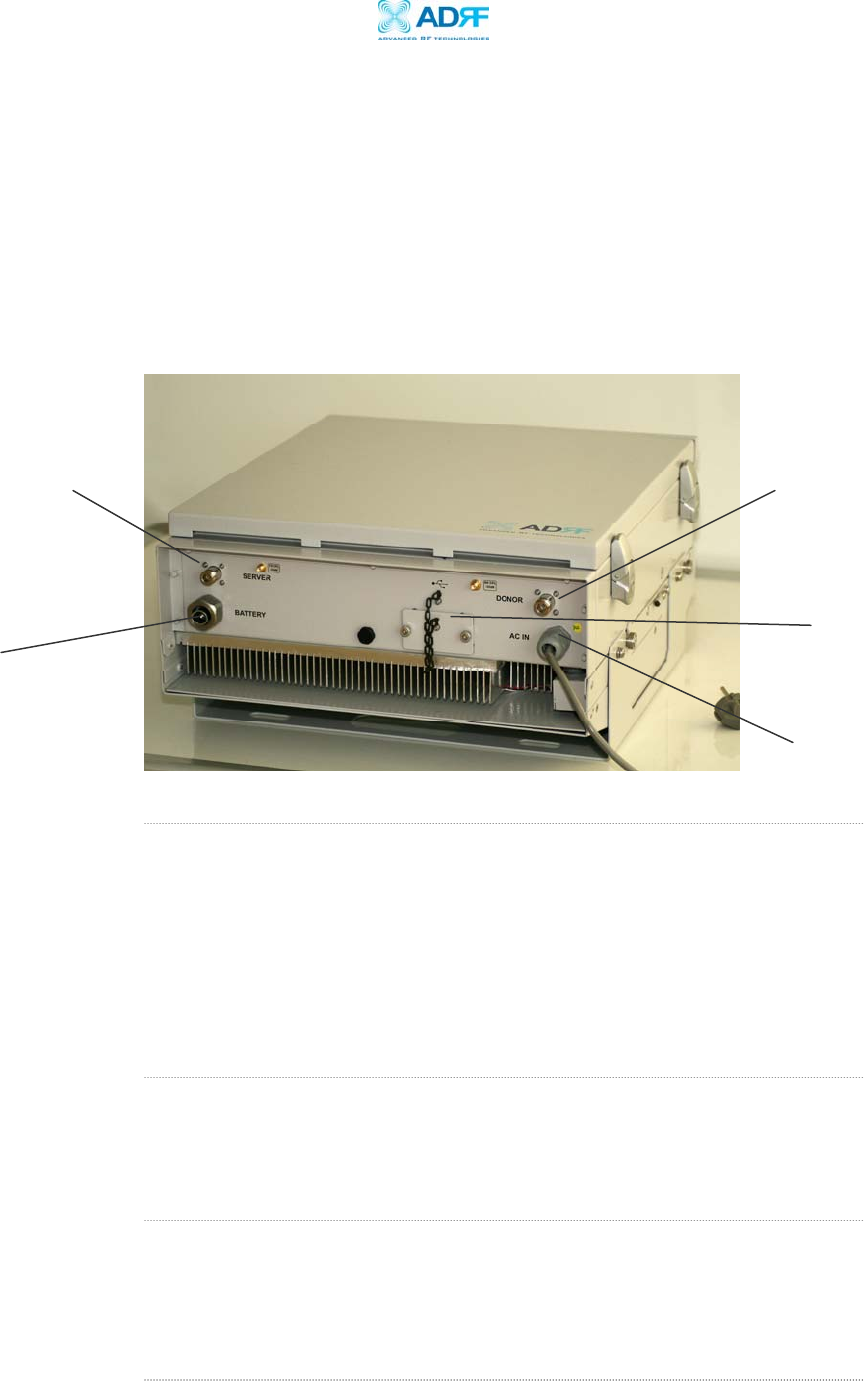
2. Connect the Power Source and Ground Wire
Make sure that the power switch inside the repeater is turned off before
connecting the power cable. Connect the power cable to the power
source as shown in Figure 3 (# 1).
** Before connecting the power cable to the power source, make sure that
the voltage source is 110 V.
3. Connect the Donor Antenna
Connect one end of the RF coaxial cable to the donor antenna and the
other end to the repeater donor port located on the bottom of the Epoch-
HP as shown in Figure 3 (# 2).
4. Connect the Server Antenna
Connect one end of the RF coaxial cable to the server antenna and
connect the other end to the repeater server port located on the bottom
of the Epoch-HP as shown in Figure 3 (# 4).
Figure 3 – Bottom Side of the Repeater
# 5 – Back-Up
Battery Cable
Opening
# 2 - Donor
Antenna Port
# 3 - Server
Antenna Port
# 4 – USB Port
# 1 - AC Power Supply

Epoch-HP RF Repeater
User Manual V1.1
Advanced RF Technologies, Inc. Proprietary Document Page 14 of 36
5. Connect the USB Cable
Using the USB cable (included in the box), connect one end of the cable to
the Epoch-HP’s USB port located on the bottom of the repeater (# 4 -
Figure 3) and the other end to the laptop’s USB port.
6. Connect the Back-Up Battery (Optional)
If a back-up battery is needed, please connect it to the power supply
located inside the repeater. You can pass the back-up battery power
cable through the opening as shown in Figure 3 (# 5).
7. Turn On the Power for Epoch-HP
Make sure that the donor and server antennas and the power cable are
securely connected to the correct ports. Turn the power switch on,
located inside the repeater.
8. Launch the Epoch-H V1.X Program
Open the Epoch-H V1.X program. You will see the Status Window.
** Please make sure that both communication status LEDs, the TX and the
RX on the bottom of the window, are blinking periodically. A green
blinking TX LED indicates that the data is being transmitted from the PC
to the Epoch-HP. A green blinking RX LED indicates that the data is
being retrieved from the Epoch-HP to the PC.
** For more detailed information on the Epoch-H V1.X, please refer to
Section 3 on page 15.
** If either the TX or the RX status LED is not blinking, check if the USB
driver has been installed. For more information, refer to Section 5,
“Troubleshooting” on page 29.
** Before proceeding to the next step, please close the cabinet door (do
not lock) at this time in order to avoid inadvertent RF feedback going
inside the repeater.”
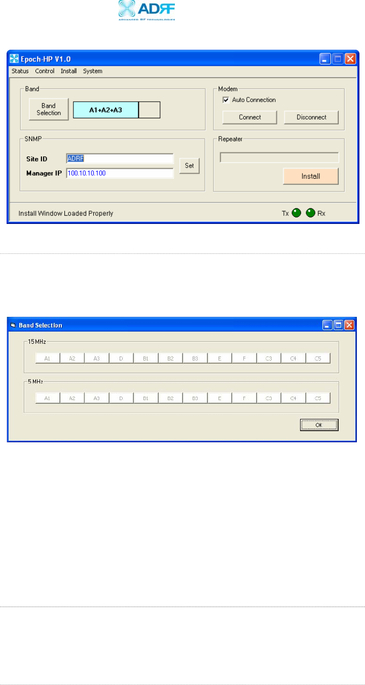
9. Go to the Install Window
Now with the blinking TX and RX status LEDs on the Status Window, go to
the Install Window. You will see the following:
Epoch-HP RF Repeater
User Manual V1.1
Advanced RF Technologies, Inc. Proprietary Document Page 15 of 36
10. Select the Desired Band or Bands
Select the desired band or bands by clicking on “Band Selection.” Once
you do so, the following window will come up:
You can select any 5 or 15 MHz block or any 5 MHz and 15 MHz
contiguous blocks at anytime.
** The above band configuration strictly depends on which model you are
using (e.g. S1, S2, or S3). Please refer to Table 1 on Page 5.
** If a wireless modem is not connected, skip steps 11 through 13 and
proceed to step 16.
11. Provide SNMP Information
Type in the Site ID and the Manager IP address as given to you by the
Wireless Provider. Once both the parameters are typed in, you must click
“Set” for it to be executed.
12. Check the Modem Connection
Figure 4 - Installation Window of the Epoch-H V1.X
Figure 5 – Band Selection Window of the Epoch-H V1.X
Epoch-HP RF Repeater
User Manual V1.1
Advanced RF Technologies, Inc. Proprietary Document Page 16 of 36
Verify that the
Auto Connection
box is checked and then click on
“Connect.”
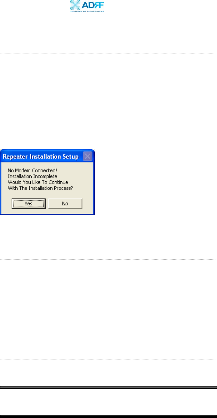
13. Click on Install
After the first three steps, click on “Install.” This installation process will
normally take less than 5 minutes.
** Please refer to the “Quick Installation Guide” for any questions or
problems that you may encounter during this installation process.
If a modem is not connected to the repeater and you click the “Install”
button, the following pop-up window will appear:
If you choose to continue with the RF portion only, simply click “Yes” and
the installation process will resume again.
14. Check the Front LED Panel
Check that the Power LED is on (Green) and neither Soft Fail LED (Yellow)
nor Hard Fail LED (Red) is lit.
** If the Soft Fail or Hard Fail LED is on, refer to Section 3.3 on page 25.
** You can go to the Status Window of the Epoch-H V1.X program to view
the basic parameters of the repeater once the repeater has installed
successfully.
17. Lock the Epoch-HP Door
Now you can lock the door using the key provided.
CONGRATULATIONS!!
The Epoch-HP Installation Process is Complete.
Figure 6 – No Wireless Modem Connected
Epoch-HP RF Repeater
User Manual V1.1
Advanced RF Technologies, Inc. Proprietary Document Page 17 of 36
3 User Manual V1.0 using Epoch-H V1.X
3.1 Menu Structure
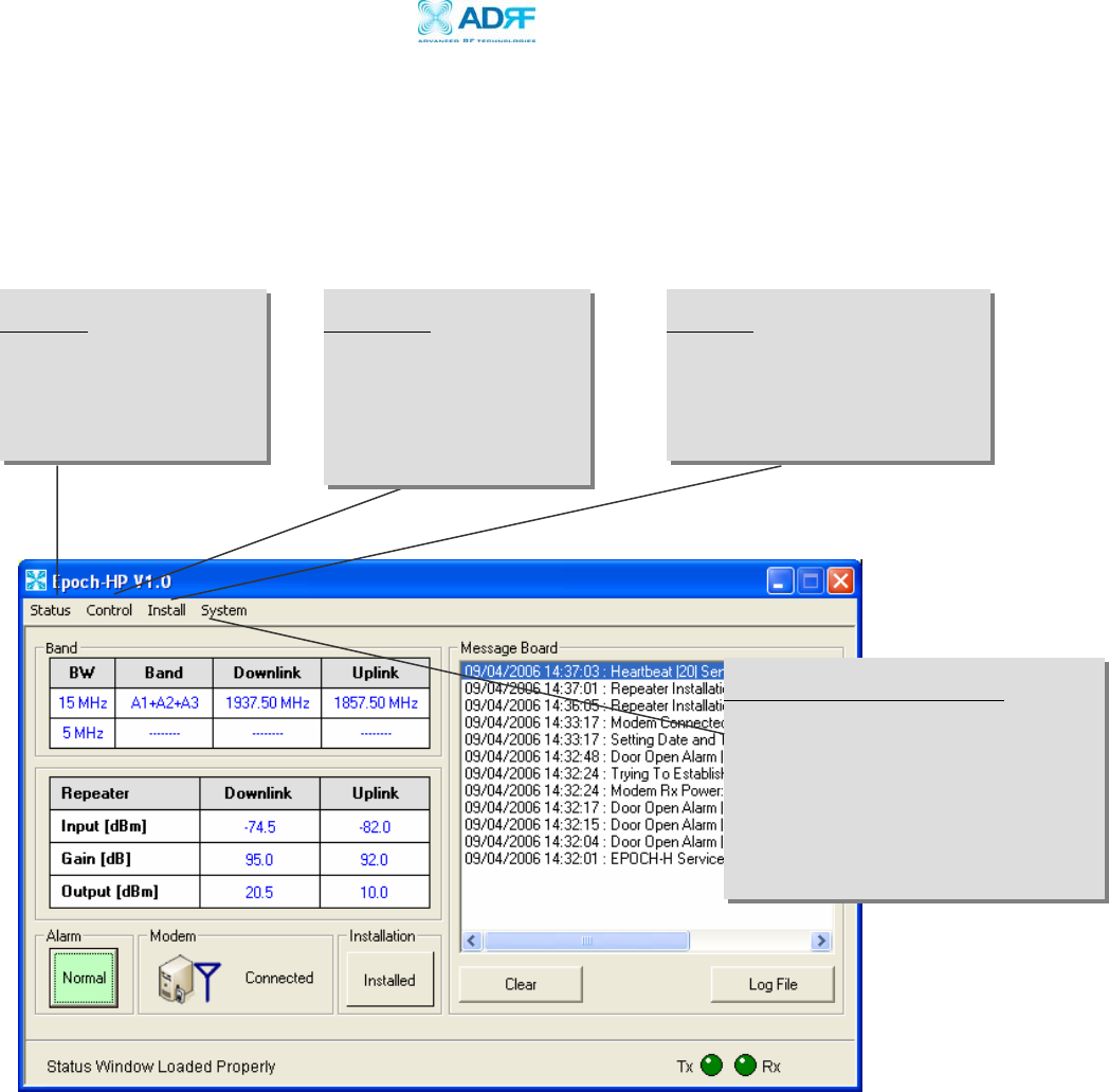
3.1.1 Window Overview
Status
The Status Window allows
you to monitor the current
settings and status of the
Epoch-HP.
Control
The Control Window enables
you to change or adjust the
Epoch-HP’s parameters and
settings.
Install
The Install Window guides you
through an automated installation
of the Epoch–HP repeater.
System Information
For more detailed system information,
click on the Info. Menu. Information
such as model number, serial number,
and firmware version of the repeater are
included here. You can also upgrade the
repeater firmware from this menu.
Figure 7 - Status Window of the Epoch-H V1.X
Epoch-HP RF Repeater
User Manual V1.1
Advanced RF Technologies, Inc. Proprietary Document Page 18 of 36
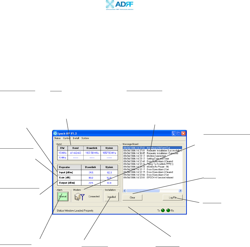
3.1.2 Status Window
The Status Window is the monitoring window of the Epoch-H V1.X. This
window enables the user to monitor the status and settings of the Epoch-
HP. In other words, no parameters can be changed in the Status Window.
To change parameters, you will need to go to the Control Window.
Band
Will display filter bandwidth,
currently selected bands, center
downlink & uplink operating
frequencies.
Repeater Input
Indicates input
signal strength of
the repeater after
being amplified by
the donor antenna
[in dBm].
Repeater Output
The output of the
repeater [in dBm]
before being radiated
by the server antenna.
Repeater Gain
Indicates the gain
of the repeater
[in dB].
Alarm Button
The alarm button changes color
to the corresponding status of
the repeater: Green for normal
operation; Yellow for soft fail
alarm; and Red for hard fail
alarm. Click on the alarm
button for detailed information.
Message Board
The user will be able to see heartbeat messages
which are sent out recently. In addition, the user
will also be able to see any alarms that are
generated along with messages once the alarms are
cleared as well.
Status Bar
Displays the status of the repeater (e.g. Status
Window Loaded Properly, etc.) and transmit
(TX) & receive (RX) communication LEDs.
Figure 8 - Status Window of the Epoch-H V1.X
Installation
Will let you know if the
repeater is properly
installed.
Modem Connection
Will let you know if the
wireless modem is
connected to the repeater
Log File
History for the
heartbeats and alarms
generated from the
repeater and can be
saved as a text file.
Clear
Will clear the
Message Board.
Epoch-HP RF Repeater
User Manual V1.1
Advanced RF Technologies, Inc. Proprietary Document Page 19 of 36
3.1.3 Control Menu
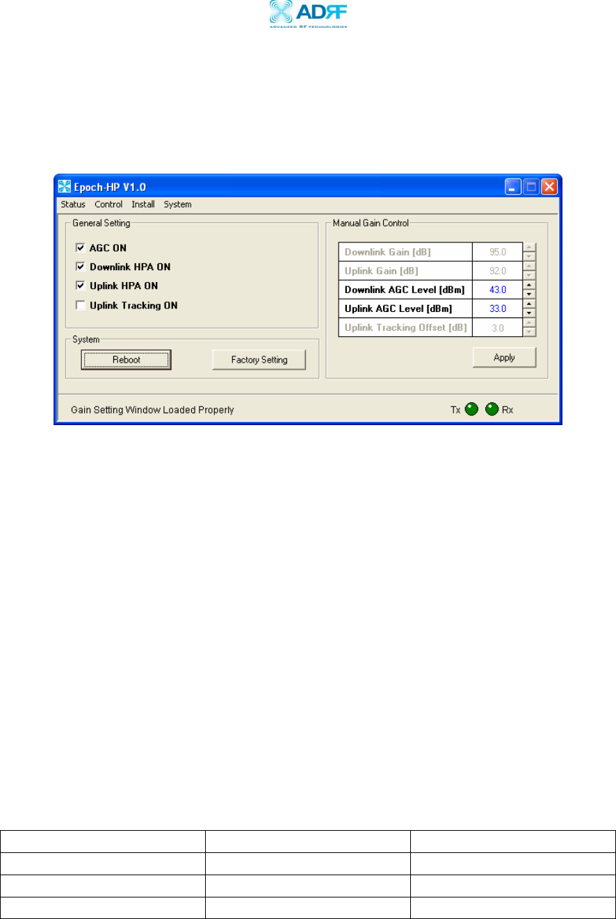
3.1.3.1 General Setting Window
AGC Mode
AGC (Auto Gain Control) adjusts the variable gain of the repeater to ensure a
constant specified output power of 37, 40 or 43 dBm (depending on the Epoch-
HP model). The functionality of the AGC feature is assured under the condition
that the input BTS signal is within the specified AGC range and that sufficient
isolation exists between antennas. By default, the
AGC ON
box is checked. To
manually change the gains in both the links,
AGC ON
must be unchecked.
If
AGC ON
is checked and
Uplink Tracking ON
is unchecked, the user can specify
the AGC level in the downlink and in the uplink respectively @ 0.5 dB step. By
default, the AGC Level is set to maximum output power in each link.
By default,
Uplink Tracking
is not checked. Once both AGC and Uplink Tacking
are
checked, this allows the user to set the AGC level in the downlink only. The
default values that will be displayed on both Downlink and Uplink AGC Levels are
the maximum output power as shown in the table below:
Output Power Level Default Downlink AGC Level Default Uplink AGC Level
5 W 43 dBm 33 dBm
10 W 40 dBm 30 dBm
20 W 37 dBm 27 dBm
Figure 9 - General Setting Window of the Epoch-H V1.X
Table 2 – Default AGC Power Level Values

Epoch-HP RF Repeater
User Manual V1.1
Advanced RF Technologies, Inc. Proprietary Document Page 20 of 36
If
Uplink Tracking ON
is unchecked, then the user can set the AGC level in both
links.
Models Gain Range AGC Input Range
Epoch-HP-05/XX
(37 dBm or 5 W Model)
65 to 95 dB -58 to -28 dBm
Epoch-HP-10/XX
(40 dBm or 10 W Model)
65 to 95 dB -55 to -25 dBm
Epoch-HP-20/XX
(43 dBm or 20 W Model)
65 to 95 dB -52 to -22 dBm
Downlink/Uplink HPA Mode
The HPA mode enables the user to turn the HPA on or off. If the HPA is turned
off on either link, the Epoch-HP will not operate properly. Both HPAs needs to
be turned on for the RF portion of the repeater to work in both directions
(downlink and uplink). By default, the
Downlink/Uplink HPA ON
box is checked.
Either or both HPAs can be turned off for troubleshooting purposes during an
installation process.
Uplink Tracking/Offset Modes
Uplink tracking mode enables or disables the
Uplink Tracking ON
feature that
sets the gain in the uplink equaling to the gain in the downlink. The tracking
gain offset is the difference in the uplink and downlink gains. For example, if
the downlink gain is 80 dB, the
Uplink Tracking ON
is checked, and the
Uplink
Tracking Gain Offset
is set to 3 dB, the uplink gain would be 77 dB.
By default, the
Uplink Tracking ON
box is not checked. If it was checked, then
the default
Uplink Tracking Offset
is set to 3 dB. This means that the uplink gain
will track the down link gain and will be 3 dB less.
Control Item Action Setting Value
Uplink Tracking ON Set Uplink Tracking Mode ON or OFF
Uplink Tracking Offset Set Tracking Gain Offset 0 ~ 25 dB @ 0.5 dB step
Table 4 - Uplink Tracking Mode and Tracking Gain Offset Range
Table 3 – AGC Input Range

Epoch-HP RF Repeater
User Manual V1.1
Advanced RF Technologies, Inc. Proprietary Document Page 21 of 36
Downlink/Uplink Gain
The gain of the Epoch-HP is the ratio of the input signal to the output signal.
The gain may be set in both links.
** The manual gain option is disabled when the AGC ON box is checked.
Reboot
By clicking the “Reboot” button, similar to how the operation works in a PC, the
control board of the repeater will restart itself.
Factory Setting
Clicking on the “Factory Setting”
button resets the settings of the repeater to the
original default factory settings as noted in the “Default Control Settings” in
Section 3.4 on page 27.
** You will lose your current saved settings once you click on “System Factory
Setting”
Epoch-HP RF Repeater
User Manual V1.1
Advanced RF Technologies, Inc. Proprietary Document Page 22 of 36
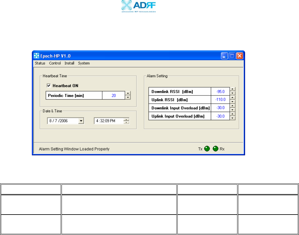
3.1.3.2 Alarm Setting Window
Control Item Action Downlink Uplink
Downlink/Uplink
RSSI Sets Low RSSI Alarm Level -120 ~ -30 dBm -120 ~ -30 dBm
Downlink/Uplink
Input Overload Sets Input Overload Level -90 ~ -20 dBm -90 ~ -20 dBm
RSSI
The RSSI alarm is the minimum RSSI value that the Epoch-HP requires to ensure
optimal coverage. The RSSI alarm will go off when the RSSI is lower than the
threshold value (refer to the RSSI value in the Alarm Setting Window).
Input Overload
A
Downlink/Uplink Input Overload
alarm occurs when the input signal strength
to the Epoch-HP exceeds the threshold value (refer to the
Uplink/Downlink Input
Overload
values in the Alarm Setting window).
Figure 10 - Alarm Setting Window of the Epoch-H V1.X
Table 4 - Alarm Threshold Values
Epoch-HP RF Repeater
User Manual V1.1
Advanced RF Technologies, Inc. Proprietary Document Page 23 of 36
Heartbeat
Heartbeat is a periodic message sent out to Wireless Provider’s NOC
only if the
repeater has a wireless modem connected to it
.
Control Item Action Setting Value
Heartbeat ON/OFF Set Heartbeat Mode ON/OFF
Periodic Time Set Heartbeat Time 1 ~ 60 min @ 1 min step
Heartbeat Mode
The Heartbeat ON box is checked by default. The heartbeat feature is only
available
if the repeater has a wireless modem connected to it
.
Periodic Time
The
Periodic Time
is the time interval between Heartbeats
only if the repeater
has a wireless modem connected to it
. The default periodic time is 20 minutes.
The periodic time can be adjusted manually between 1 to 60 minutes.
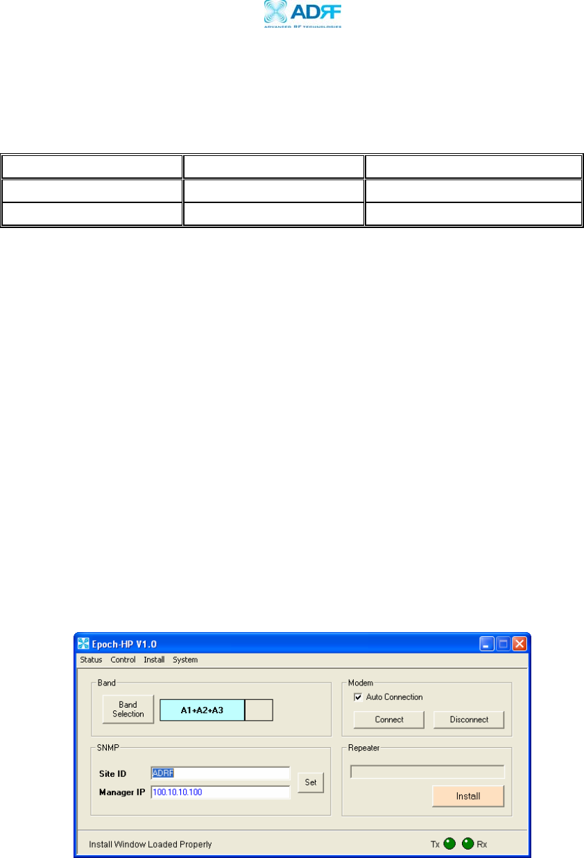
3.1.4 Install Window
At the time of installation, the installer needs to go to the Install Window of the
Epoch-H V1.X. The Install Window will guide the installer through a step by step
process to properly install the Epoch-HP repeater.
For setup or installation of a repeater, go to the Install
Window.
Figure 11 - Install Window of the Epoch-H V1.X
Table 6 - Heartbeat Mode and Time Ran
g
e
Epoch-HP RF Repeater
User Manual V1.1
Advanced RF Technologies, Inc. Proprietary Document Page 24 of 36
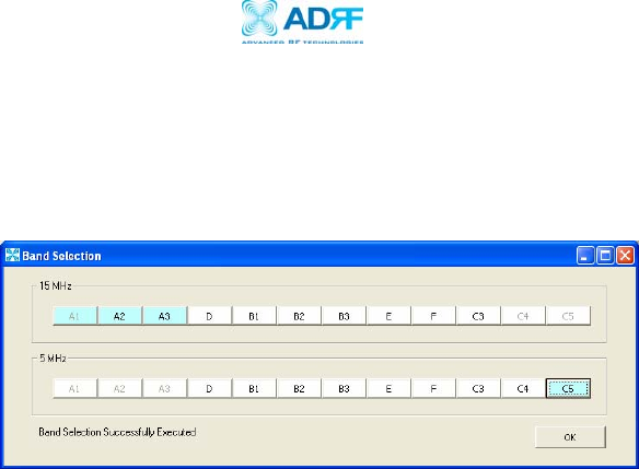
Band
Select the desired band or bands by clicking on “Band Selection.” Once
you do so, the following window will come up:
You can select any 5 or 15 MHz block or any 5 MHz and 15 MHz
contiguous blocks at anytime.
** If a wireless modem is not connected to the repeater, simply select the
desired operating band(s) and click on “Install.”
SNMP
(only applicable if a wireless modem is connected to the repeater)
a. Site ID
The
Site ID
is a unique ID for each site and will be provided by the
Wireless Provider.
b. Manager IP
The
Manager IP
address will be provided by the Wireless Provider. The
repeater will send alarms to the Wireless Provider’s NOC to the assigned
Manager IP address.
Modem
(only applicable if a wireless modem is connected to the repeater)
The
Auto Connection
box needs to be checked when the wireless modem
is installed inside the repeater. A wireless modem is used in order to
send the alarms and the heartbeat over the air to the Wireless Provider’s
NOC.
Repeater
Click the “Install” button and the repeater will setup automatically.
For information regarding the use of the Epoch-H V1.X during installation, refer
to Section 2.7.1 on page 12, “Repeater Installation” (starting at number 8).
Figure 12 – Band Selection Window of the Epoch-H V1.X
Epoch-HP RF Repeater
User Manual V1.1
Advanced RF Technologies, Inc. Proprietary Document Page 25 of 36
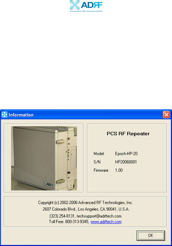
3.1.5 System Menu
3.1.5.1 Information
The Info. Window displays the following: (1) Model Number; (2) Serial
Number; and (3) Firmware Version of the Epoch-HP repeater. Contact
information is included along with a link to Advanced RF Technologies, Inc.’s
URL.
Figure13 - Info. Window of the Epoch-H V1.X
Epoch-HP RF Repeater
User Manual V1.1
Advanced RF Technologies, Inc. Proprietary Document Page 26 of 36
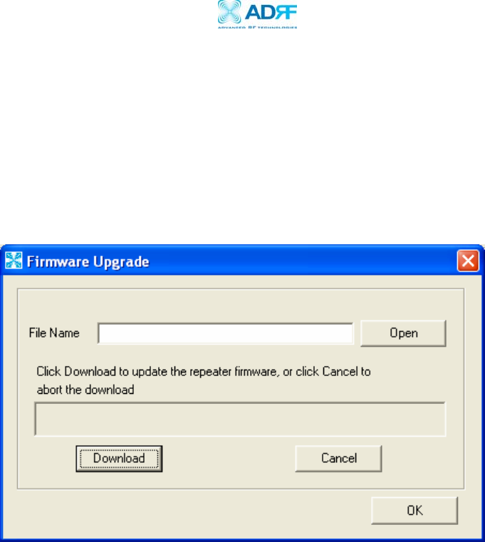
3.1.5.2 Firmware Upgrade
The Firmware Upgrade Window enables you to upgrade the firmware of the
repeater. The latest version of the firmware will be provided to you by ADRF.
Save the latest version of the firmware on your PC. Click on Open and locate
the firmware from your PC. Click on Download and automatically the latest
version of the firmware will be downloaded onto the repeater.
3.2 Using the Epoch-H V1.X
3.2.1 Changing Parameters
In changing the parameters of the repeater via use of the Epoch-H V1.X,
note that the values entered into the Epoch-H V1.X are limited to the
ranges and modes specified in the Menu Structure section as explained in
Section 3.1 on page 15.
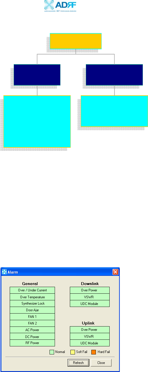
The Organizational Chart below shows (alphabetically) the parameters
that can be changed and the location of each parameter in the Menu
Structure. The asterisk “*” denotes parameters that apply to both uplink
and downlink.
Figure 14 – Firmware Upgrade Window of the Epoch-H V1.X
Epoch-HP RF Repeater
User Manual V1.1
Advanced RF Technologies, Inc. Proprietary Document Page 27 of 36
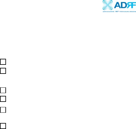
3.3 Alarms
All the various alarms that are supported by Epoch-HP can be viewed by clicking the
“Alarm” button on the Status Window. If a soft fail alarm should occur, the alarm of
concern would be highlighted in yellow. In the same manner, the corresponding
hard fail alarm would be highlighted in red. In order to find out what is causing the
alarm(s), simply place the mouse cursor over the highlighted yellow or red alarm box
(Note: only applicable to some of the alarms)
and a tool tip message will appear,
displaying the threshold value and the current measured value. To update the
window, click the “Refresh” button.
Control Menu
General
Setting
Alarm
Setting
Reboot
Factory Setting
Manual Gain Control*
AGC Level Control*
Uplink Tracking Offset
Periodic Time
RSSI*
Input Overload*
Figure 15 - Variable Parameters in the Epoch-H V1.X
Figure 16 - All Alarm Parameters Supported by Epoch-H V1.X

Epoch-HP RF Repeater
User Manual V1.1
Advanced RF Technologies, Inc. Proprietary Document Page 28 of 36
In the event of a hard fail alarm, the control board will shutdown the HPA (both
uplink & downlink) for 30 seconds and then turns on the HPA to check for a
repeated hard fail occurrence. If the next two occurrences sense a hard fail, the
control board will shutdown the HPA for 20 minutes (total of three consecutive hard
fails). After 20 minutes, the HPA will automatically come back alive and the control
board will check if the Hard Fail alarm has cleared. If it has not, the same process
will continue as mentioned above.
3.3.1 General (Fixed Parameter) Alarms
Alarm List Soft Fail Hard Fail Comments
Over/Under Current O O Soft Fail: Less than 0.5 A @ under current
Hard Fail: More than 7.5 A @ over current
Over Temperature O O Soft Fail: 158 ~ 185 °F
Hard Fail: > 185 °F
Synthesizer Lock - O Band selection will not work properly
VSWR - O > 1.5:1
Low Isolation/OSC. - O Repeater will be in an oscillating state
RF Power - O Will occur in the event of any
Hard Fail alarm
3.3.2 Downlink/Uplink Alarms
Alarm List Soft Fail Hard Fail Remark
RSSI O -
Input Power Overload O -
Downlink
(Forward)
Over Power* O O
RSSI O -
Input Power Overload O -
Uplink
(Reverse)
Over Power* O O
Alarms will turn on if the
value is not within operable
limits specified in the
Control Alarm Setting
Window.
Note: The Over Power
parameter is fixed and
cannot be modified by
the user.
Table 7 - General (Fixed Parameter) Alarms of the Epoch-H V1.X
Table 8 – List of Alarm Settings of the Epoch-H V1.X

Epoch-HP RF Repeater
User Manual V1.1
Advanced RF Technologies, Inc. Proprietary Document Page 29 of 36
The example below distinguishes the difference between an over power soft
failure and an over power hard failure:
The threshold value for the downlink over power parameter is set to 45.0 dBm
(factory set value for the 20 W model), a Hard Fail alarm would occur if the
downlink over power value was greater than 45.0 dBm (43 dBm is the maximum
composite power allowable). Similarly, a Soft Fail alarm would occur if the
downlink over power value was greater than 44.0 dBm but less than 45.0 dBm.
Vice versa, the same example is also applicable in the uplink side.
3.4 Default Control Settings
3.4.1 Default General Setting
Control Item Setting Value
AGC Mode ON
Downlink/Uplink HPA Mode ON
Uplink Tracking Mode ON
Downlink/Uplink Gain 80 dB
Downlink/Uplink AGC Level
DL: 37/40/43 dBm
UL: 27/30/33 dBm
(depending on model)
Tracking Gain Offset 3 dB
a. When
Uplink Tracking ON
mode is enabled by default, the
Tracking Gain
Offset
is set to 3 dB.
b. When
AGC ON
mode
is enabled, by default, the
Downlink/Uplink AGC
Level
is set to 37/40/43 dBm (depending on model).
3.4.2 Default Alarm Setting
Setting Value
Control Item Downlink Uplink
RSSI -95 dBm -110 dBm
Input Overload -30 dBm -30 dBm
Heartbeat On/Off ON
Heartbeat Time 20 minutes
Table 10 - Default Alarm Parameter Values of the Epoch-H V1.X
Table 9 - Adjustable Alarm Settings of the Epoch-H V1.X
Epoch-HP RF Repeater
User Manual V1.1
Advanced RF Technologies, Inc. Proprietary Document Page 30 of 36
4 Maintenance Guide for Epoch-HP
4.1 Periodic Inspection Checklist
a. Ensure that the door is closed and locked before inspection.
b. Check for loose connections to the repeater and antennas. If connections
are loose, make sure that all connections are tightly fastened properly.
c. Cables and connectors are in good condition.
d. Open the repeater door to check that the repeater is turned on.
e. Check that all components inside are intact with no unusual wear (e.g., rust,
dirt, etc.).
f. Ensure that the repeater brackets (if used) are in good condition and that
the repeater is securely fastened.
4.2 Preventive Measures for Optimal Operation
4.2.1 Recommendations
• Perform the
Periodic Inspection Checklist
quarterly or semiannually.
• Always lock the door to the repeater to prevent unauthorized access.
4.2.2 Precautions
• Do not operate the repeater with the antennas in extremely close
proximity as this may cause damage to the repeater.
• Do not shut down the repeater unless absolutely necessary (in the case
where the repeater is a hazard to safety).
• Do not change parameters unless instructed to do so by an authorized
supervisor.
• Do not move the repeater unless instructed to do so by an authorized
supervisor.
• Do not detach any cables to the repeater unless repair of respective
components are necessary.

Epoch-HP RF Repeater
User Manual V1.1
Advanced RF Technologies, Inc. Proprietary Document Page 31 of 36
5 Troubleshooting
5.1 Epoch-H V1.X Scenarios
Tx Rx Explanation
RED RED
The USB port can not send or receive data. Check the USB port
connection to the computer and the repeater. Ensure that the
repeater is turned on and that the connection to the repeater is
secure.
Blinking
GREEN RED
The repeater is not receiving any commands from the
software. Ensure that the repeater is tuned on and check for
proper USB port connection.
Blinking
GREEN
Solid
GREEN
The repeater is not receiving any commands from the
software. In this state, the repeater is either processing or
executing a command. Wait for a few seconds for the Rx LED
to blink periodically.
Blinking
GREEN
Blinking
GREEN
Successful Connection. The Epoch-H V1.X and the repeater are
communicating successfully.
Note: The Tx/Rx LEDs will blink periodically only on the Status Window.
5.2 Common Installation Problems
Problem Possible Solution
The power
green LED on
the second
panel is not lit.
Check if the power supply switch is turned on by opening the
second door of the repeater.
Software &
Laptop - No
Communication
Please verify if the USB driver has been installed.
Status Window –
Weak Signal or
Donor RSS
Option 1: Check that the donor and server antennas are
connected to the proper antenna ports on the repeater.
Option 2: Reposition or rotate the donor antenna around until
a stronger signal is received.
Low Isolation or
Oscillation
Increase the separation between the donor and server
antennas by moving the antennas around or by rotating them.
Downlink/Uplink
VSWR Alarm
Check the cabling because RF signals maybe leaking and also
verify that the connectors are tightly secured.
Downlink/Uplink
Input Power
Overload Alarm
Option 1: Add an attenuator after the donor/server antenna to
reduce the strong donor/server signal coming into the
repeater.
Table 9 - Tx and Rx LEDs

Epoch-HP RF Repeater
User Manual V1.1
Advanced RF Technologies, Inc. Proprietary Document Page 32 of 36
Option 2: An oscillation in the system could cause this alarm.
Check if there is sufficient separation between the donor and
the server antennas.
Downlink/Uplink
Over Power
Alarm
Option 1: Add an attenuator after the donor/server antenna to
reduce the strong donor/server signal coming into the
repeater.
Option 2: An oscillation in the system could cause this alarm.
Check if there is sufficient separation between the donor and
the server antennas.
Table 11 – Troubleshootin
g
Ti
p
s

Epoch-HP RF Repeater
User Manual V1.1
Advanced RF Technologies, Inc. Proprietary Document Page 33 of 36
6 Warranty and Repair Policy
6.1 General Warranty
The Epoch-HP carries a Standard Warranty period of two (2) years unless indicated
otherwise on the package or in the acknowledgment of the purchase order.
6.2 Limitations of Warranty
Your exclusive remedy for any defective product is limited to the repair or
replacement of the defective product. Advanced RF Technologies, Inc. may elect
which remedy or combination of remedies to provide in its sole discretion.
Advanced RF Technologies, Inc. shall have a reasonable time after determining that a
defective product exists to repair or replace a defective product. Advanced RF
Technologies, Inc. warranty applies to repaired or replaced products for the balance
of the applicable period of the original warranty or ninety days from the date of
shipment of a repaired or replaced product, whichever is longer.
5.3 Limitation of Damages
Advanced RF Technologies, Inc. entire liability for any defective product shall in no
event exceed the purchase price for the defective product.
5.4 No Consequential Damages
Advanced RF Technologies, Inc. has no liability for general, consequential, incidental
or special damages.
5.5 Additional Limitation on Warranty
Advanced RF Technologies, Inc. standard warranty does not cover products which
have been received improperly packaged, altered, or physically damaged. For
example, broken warranty seal, labels exhibiting tampering, physically abused
enclosure, broken pins on connectors, any modifications made without Advanced RF
Technologies, Inc. authorization, will void all warranty.
5.6 Return Material Authorization (RMA)
No product may be returned directly to Advanced RF Technologies, Inc. without first
getting an approval from Advanced RF Technologies, Inc. If it is determined that
the product may be defective, you will be given an RMA number and instructions in
how to return the product. An unauthorized return, i.e., one for which an RMA

Epoch-HP RF Repeater
User Manual V1.1
Advanced RF Technologies, Inc. Proprietary Document Page 34 of 36
number has not been issued, will be returned to you at your expense. Authorized
returns are to be shipped prepaid and insured to the address on the RMA in an
approved shipping container. You will be given our courier information. It is
suggested that the original box and packaging materials should be kept if an
occasion arises where a defective product needs to be shipped back to Advanced RF
Technologies, Inc. To request an RMA, please call (323) 254-8131 or send an email
to techsupport@adrftech.com.

Epoch-HP RF Repeater
User Manual V1.1
Advanced RF Technologies, Inc. Proprietary Document Page 35 of 36
Appendix A: Specifications
A.1 Repeater Specifications
ELECTRICAL SPECIFICATIONS
PARAMETERS SPECIFICATIONS COMMENTS
DL 1930 to 1990 MHz Frequency
Range UL 1850 to 1910 MHz
Sub Band Filtering 5 MHz, 15 MHz or 20 MHz
Any 5MHz @ 60MHz
Any 15MHz @ 60MHz
Any 5+ 15MHz @ 60MHz
Operating Frequency Programmable
Frequency Error ≤ +/- 0.05 ppm
System Delay ≤ 5 usec Each Band
Repeater Gain 65 to 95 dB
20 W +43 dBm / +33 dBm
10 W +40 dBm / +30 dBm
Maximum
DL / UL
Output Power 5 W +37 dBm / +27 dBm
Composite
DL AGC Range 30 dB
UL AGC Range 30 dB
AGC Step Size 0.5 dB
Gain Linearity ≤ +/- 0.8 dB
≤ 3.0 dB Peak to Peak @ Each Band
Gain Flatness ≤ 4.0 dB Peak to Peak @ Full Band
≤ -45 dBc @ Fc +/- 885 KHz
≤ -55 dBc @ Fc +/- 1.98 MHz
Spectral Mask Emission
< -13 dBm @ Fc +/- 2.25 MHz
Rho Factor ≥ 0.96
Noise Figure Maximum 5 dB @ Maximum Gain
VSWR ≤ 1.5:1

Epoch-HP RF Repeater
User Manual V1.1
Advanced RF Technologies, Inc. Proprietary Document Page 36 of 36
MECHANICAL SPECIFICATIONS
PARAMETERS SPECIFICATIONS COMMENTS
Cabinet Size 18.11 x 20.08 x 9.55 inches W x H x D
(Including Bracket)
Cabinet Weight 73 lbs Including Bracket
Cabinet Mount Type Utility Pole Mount
Antenna N-Type (F)
Coupling SMA (F) 30 dB
Frame Ground Lug Terminal (5.5SQ)
Connector
Type
Control USB
Cooling Forced Air Cooling 2 FAN
Weatherproofing NEMA 4, IP65
POWER SPECIFICATIONS
PARAMETERS SPECIFICATIONS COMMENTS
Main AC Power 100 or 240 V AC Select Switch Type
AC Frequency 50 to 65 Hz
20 W 500 Watts
10 W 360 Watts
Power
Consumption 5 W 250 Watts
AC Supply Protection Fuse
Grounding External Threaded Stud
ENVIRONMENTAL SPECIFICATIONS
PARAMETERS SPECIFICATIONS COMMENTS
Operating Temperature -22 ˚F to +122 ˚F
Storage Temperature -40 ˚F to +176 ˚F
Humidity 5 to 95%, RH