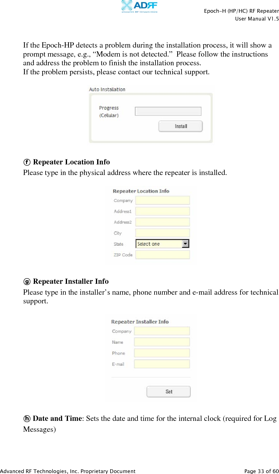
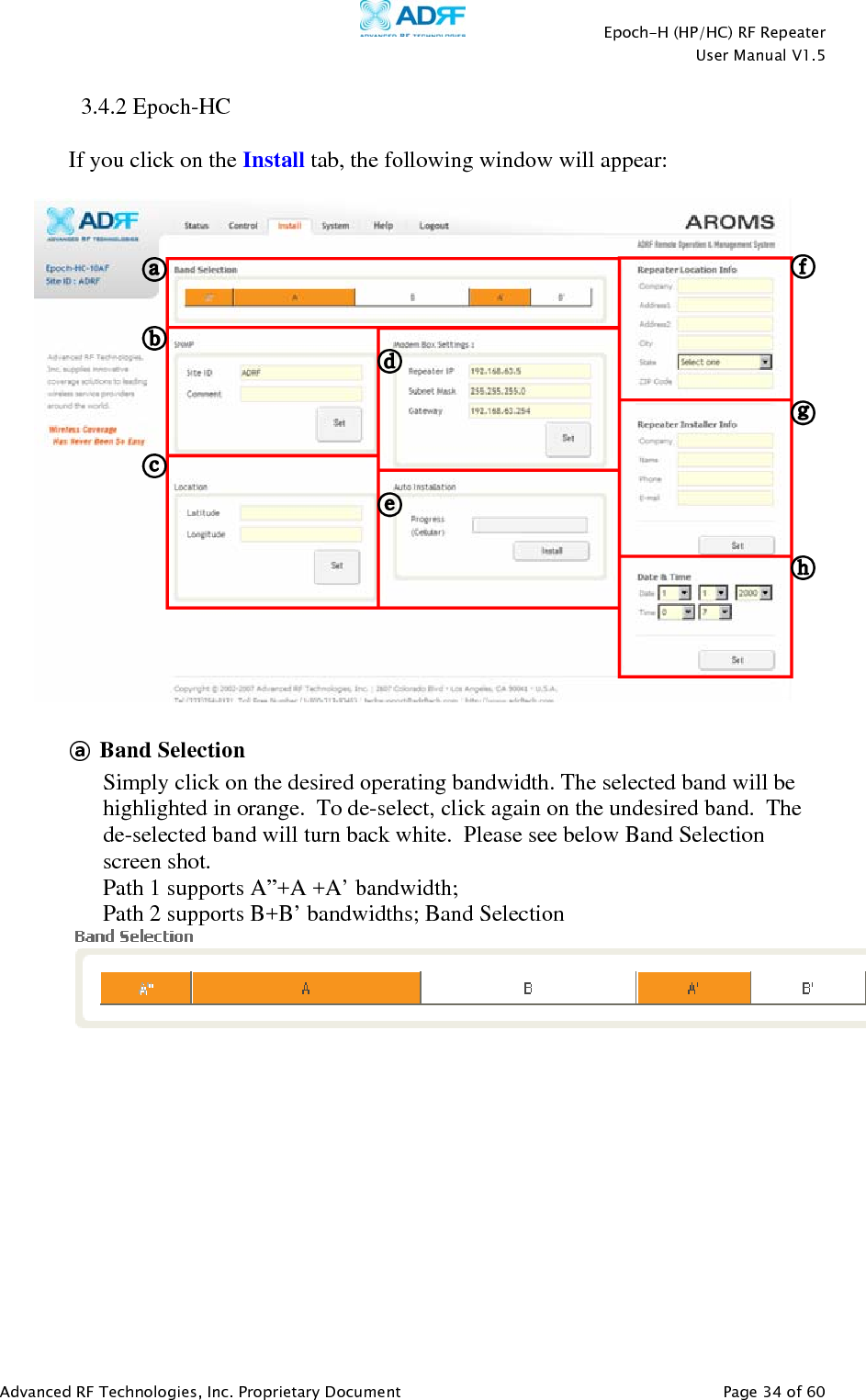
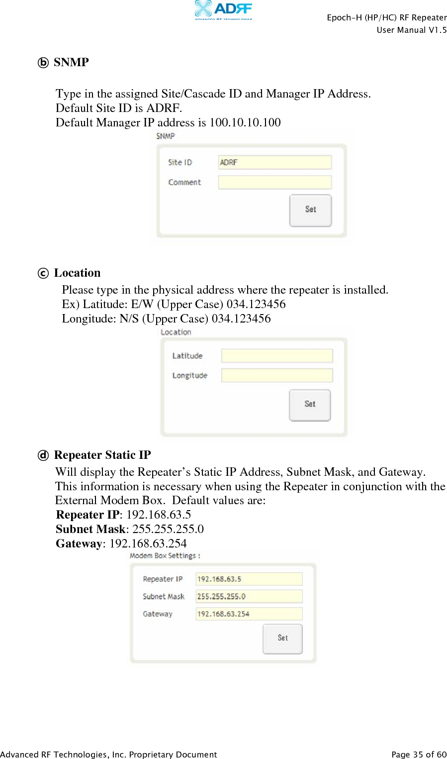
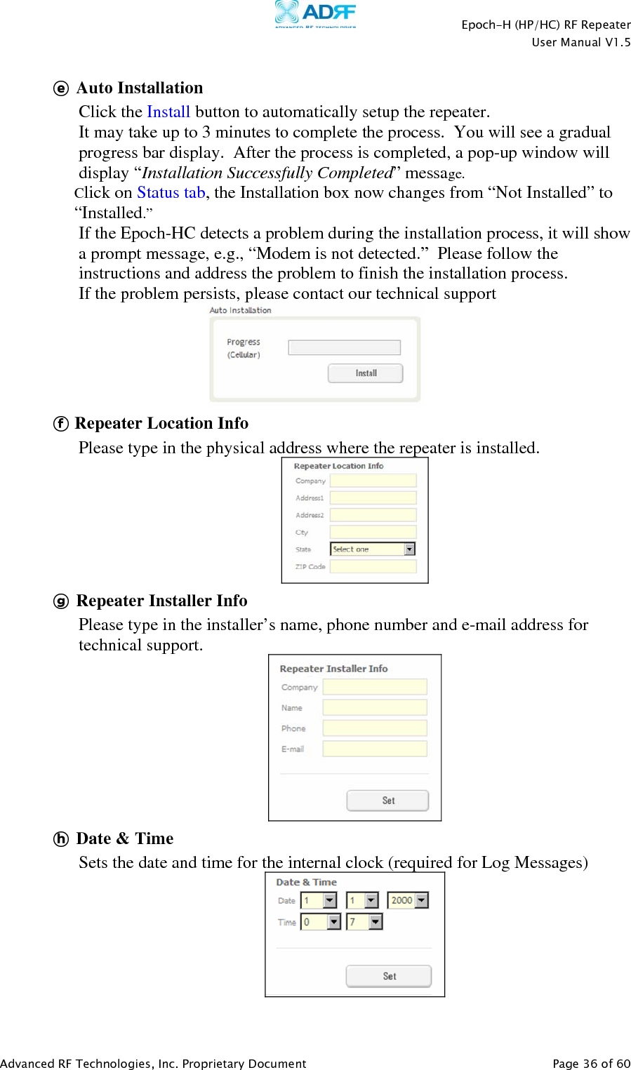
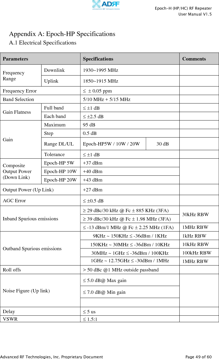
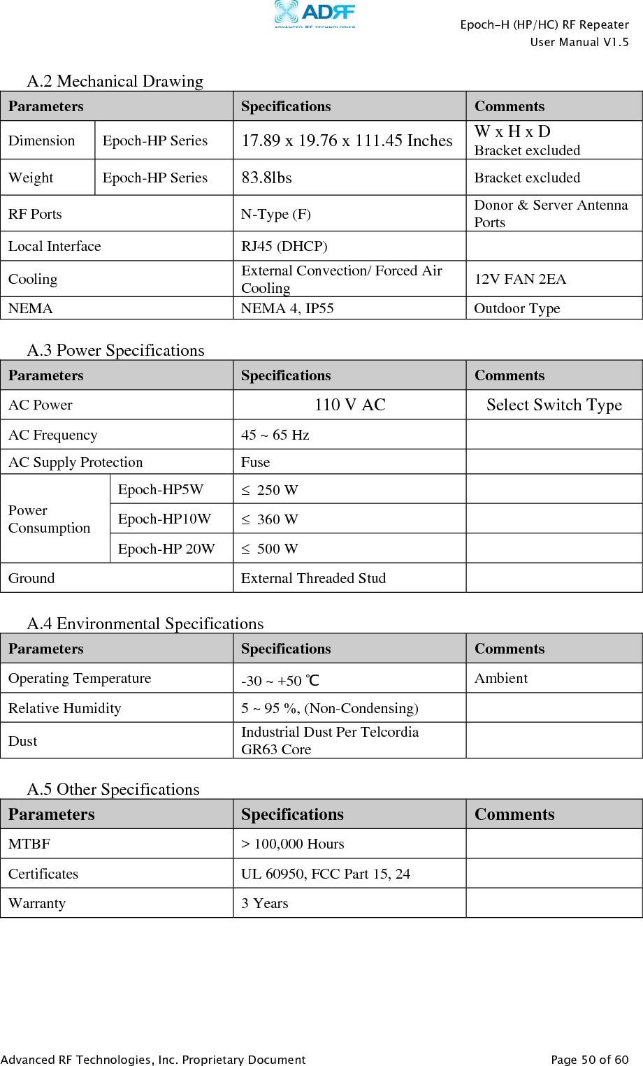
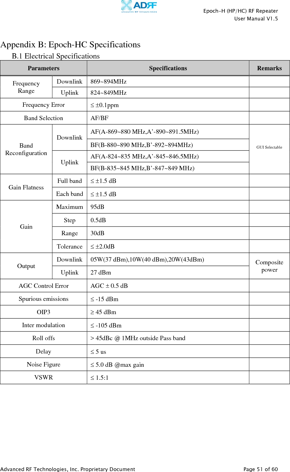
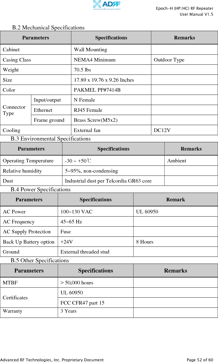
Advanced RF Technologies EPOCHHC Cellular Band Repeater User Manual Epoch H 1 5

Advanced RF Technologies, Inc. Cellular Band Repeater Epoch H 1 5

Users manual

    Advanced RF Technologies, Inc. Proprietary Document   Page 1 of 60        EPOCH-H (HP/HC) USER MANUAL   Version 1.5           3116 Vanowen St. Burbank, CA 91505 USA Tel: 818-840-8131 Fax: 818-840-8138 www.adrftech.com
   Epoch-H (HP/HC) RF Repeater  User Manual V1.5  Advanced RF Technologies, Inc. Proprietary Document   Page 2 of 60   Glossary The following is a list of abbreviations and terms used throughout this document.  Abbreviation/Term  Definition AGC Automatic Gain Control ALC  Automatic Level Control AROMS  ADRF’s Repeater Operation and Management System BTS Base Transceiver Station CDMA  Code Division Multiple Access CW Continuous Wave (un-modulated signal) DAS Distributed Antenna System DL Downlink Downlink  The path covered from the Base Transceiver Station (BTS) to the subscribers service area via the repeater HPA High Power Amplifier HW Hardware iDEN  Integrated Digital Enhanced Network IF Intermediate Frequency LNA Low Noise Amplifier MS  Mobile Station  PLL  Phased Locked Loop PS Power Supply RF Radio Frequency SW Software UL Uplink Uplink  The path covered from the subscribers service area to the Base Transceiver Station(BTS) via the repeater  VSWR  Voltage Standing Wave Ratio
   Epoch-H (HP/HC) RF Repeater  User Manual V1.5  Advanced RF Technologies, Inc. Proprietary Document   Page 3 of 60   Version 1.5 (Modified December 7, 2009)  Information in this document is subject to change without notice. Advanced RF Technologies, Inc. 1996-2009 All rights reserved.  Please send comments to:  E-Mail:  info@adrftech.com   Phone:   (818) 840-8131  Fax:   (818) 840-8138  Address:  Advanced RF Technologies, Inc.   Attention: Technical Publications Department 3116 Vanowen St. Burbank, CA 91505 USA www.adrftech.com
   Epoch-H (HP/HC) RF Repeater  User Manual V1.5  Advanced RF Technologies, Inc. Proprietary Document   Page 4 of 60   Revision History for Manual Version  Author  Description  Date 1.0  G.T Kim  First Generation.  February 2007 1.1  G.T Kim  User GUI Upgrade  May 4, 2007 1.2  G.T Kim  UDC Module Upgrade  December 17, 2008 1.3  K.Y Lee  Changed UDC, Changed Digital Board, Change Manual Update  October  2008 1.4  K.Y Lee  Added Ethernet  March 27, 2009 1.5  Sun Kim  Address Change December 7, 2009   Revision History for Hardware Version  Author  Description  Date 1.0  Digital Part  First Generation.  February 2007 RF Hardware  First Generation. 2.0  Digital Part  Added Watch Dog  May 4, 2007 RF Hardware  UDC Module Upgrade 3.0  Digital Part  Upgrade for Internal Block October  2008 RF Hardware  Changed UDC, Changed Digital Board, Change Manual Update 3.2  Digital Part  Added EVDO Detector for Input   November  2008 RF Hardware  - 4.0  Digital Part  Added Ethernet  March 5, 2009 RF Hardware  -       Revision History for Firmware Version  Author  Description  Date 1.00  Software Team  First Generation. February 2007 1.12    User GUI Upgrade  May 4, 2007 1.13    Added GSM Function.   2.01   Added Watch Dog   2.04    Added Back up Battery   3.00.15    Firmware Unification Phase 1  February 20, 2009 3.00.16    Added GSM Function.  February 24, 2009 4.00.36    Added Ethernet  March 13, 2009
   Epoch-H (HP/HC) RF Repeater  User Manual V1.5  Advanced RF Technologies, Inc. Proprietary Document   Page 5 of 60   Table of Contents  1. Introduction of Epoch-H ............................................................................. 7 1.1 Introduction ...................................................................................................... 7 1.1.1 Highlights ............................................................................................. 7 1.1.2 Available Models .................................................................................... 8 1.1.3 Parts List ............................................................................................ 10 1.1.4 Repeater Quick View ............................................................................. 11 1.2 Warnings and Hazards ....................................................................................... 13 2. Epoch-H Overview ................................................................................... 15 2.1 Switches & Indicators ....................................................................................... 15 2.1.1 LEDs ................................................................................................. 15 2.1.2 AC Power Switch .................................................................................. 16 2.1.3 Back Up Battery Switch & Battery Port ...................................................... 16 2.1.4 Ethernet Port ........................................................................................ 17 2.1.5 Modem Module .................................................................................... 17 2.1.6 Other Ports .......................................................................................... 18 2.2 Installation ..................................................................................................... 18 2.2.1 Tools ................................................................................................. 18 2.2.2 Procedure ............................................................................................ 18 2.2.3 Grounding ........................................................................................... 20 2.3 Antenna Separation/Isolation ............................................................................... 21 2.4 Line of Sight ................................................................................................... 22 3. Epoch-H AROMS Setup ...........................................................................  23 3.1 Repeater/PC Connection Using AROMS ............................................................... 23 3.2 Repeater Status ............................................................................................... 25 3.2.1 Epoch-HP ........................................................................................... 25 3.2.2 Epoch-HC ........................................................................................... 26 3.3 Repeater Control .............................................................................................. 28 3.4 Repeater Install ............................................................................................... 31 3.4.1 Epoch-HP ........................................................................................... 31 3.4.2 Epoch-HC ........................................................................................... 34 3.5 Repeater System .............................................................................................. 37 4. Maintenance Guide for Epoch-H ..............................................................  39 4.1 Periodic Inspection Checklist .............................................................................. 39 4.2 Preventive Measures for Optimal Operation ............................................................ 39 5. Epoch-H Series Troubleshooting Guide ...................................................  40 5.1 Connectivity Guide for LAN ............................................................................... 40 5.2 Troubleshooting Guide for Repeater ...................................................................... 43 6. Warranty and Repair Policy ......................................................................  47 6.1 General Warranty ............................................................................................ 47
   Epoch-H (HP/HC) RF Repeater  User Manual V1.5  Advanced RF Technologies, Inc. Proprietary Document   Page 6 of 60   6.2 Limitations of Warranty .................................................................................... 47 6.3 Limitation of Damages ..................................................................................... 47 6.4 No Consequential Damages ............................................................................... 47 6.5 Additional Limitation on Warranty ...................................................................... 47 6.6 Return Material Authorization (RMA) .................................................................. 48 6.7 Warranty and Repair Policy ...................................... Error! Bookmark not defined. Appendix A: Epoch-HP Specifications ........................................................ 49 A.1 Electrical Specifications .................................................................................... 49 A.2 Mechanical Drawing ........................................................................................ 50 A.3 Power Specifications ........................................................................................ 50 A.4 Environmental Specifications ............................................................................. 50 A.5 Other Specifications ......................................................................................... 50 Appendix B: Epoch-HC Specifications ........................................................ 51 B.1 Electrical Specifications .................................................................................... 51 B.2 Mechanical Specifications ................................................................................. 52 B.3 Environmental Specifications ............................................................................. 52 B.4 Power Specifications ........................................................................................ 52 B.5 Other Specifications ......................................................................................... 52 Appendix C: Epoch-H Mechanical Drawing ................................................ 53 Appendix D: Epoch-HP Overview ............................................................... 54 D.1 Black Diagram ............................................................................................... 54 D.2 Components ................................................................................................... 55 Appendix E: Epoch-HC Overview ............................................................... 57 E.1 Block Diagram ................................................................................................ 57 E.2 Components ................................................................................................... 58
   Epoch-H (HP/HC) RF Repeater  User Manual V1.5  Advanced RF Technologies, Inc. Proprietary Document   Page 7 of 60   1. Introduction of Epoch-H  1.1 Introduction  Epoch-H series repeaters enhance outdoor wireless coverage in the most effective and cost efficient way.  For its intelligent design and versatility, Epoch-H series repeaters are the ideal choice for wireless coverage problems outdoors.   In many large scale in-building applications, Epoch-H series repeaters can also be used (e.g. malls, campuses, stadiums, etc.) with passive antennas instead of a DAS (distributed antenna system) and offer significant cost savings.  **Using ADRF’s ‘High Isolation Antennas’, will allow for enhanced performance by creating higher isolation.  Please contact ADRF Sales for more information.  1.1.1 Highlights EPOCH-HP • Covers the 65 MHz PCS band, including G band • Down Link 37, 40 or 43dBm Composite Output Power • Up Link 27dBm max Composite Output Power • 95 dB gain • 30 dB AGC Range @ 0.5 dB Step • Can Set AGC Output Power Level  • Automated installation   • Web GUI via DHCP  • Band Selectable via Web GUI • Can Support Non-Contiguous Bands • Supports Embedded Wireless Modem • Supports Network Management Monitoring System via SNMP   EPOCH-HC • Covers the 25 MHz Cellular band (AF/BF) • Down Link 37, 40 or 43dBm Composite Output Power • Up Link 27dBm max Composite Output Power • 95 dB gain • 30 dB AGC Range @ 0.5 dB Step • Can Set AGC Output Power Level  • Band Selectable via Software • Supports Embedded Wireless Modem • Supports Network Management Monitoring System via SNMP   ** Special band combinations are also supported in all the models. ** Please contact ADRF Sales for any special band combination request.
   Epoch-H (HP/HC) RF Repeater  User Manual V1.5  Advanced RF Technologies, Inc. Proprietary Document   Page 8 of 60   1.1.2 Available Models  Product ID  Description Epoch-HP-05W Down Link: 5 W (37dBm) composite output power with 95 dB of gain (30 dB dynamic AGC range).  Up Link: 0.5W (27dBm) composite output power with 95 dB of gain (30 dB dynamic AGC range).  Supports up to Two (2) non-contiguous band combinations (5/10 + 5/15MHz) Epoch-HP-10W Down Link: 10 W (40dBm) composite output power with 95 dB of gain (30 dB dynamic AGC range).  Up Link: 0.5W (27dBm) composite output power with 95 dB of gain (30 dB dynamic AGC range).  Supports up to Two (2) non-contiguous band combinations (5/10 + 5/15MHz) Epoch-HP-20W Down Link: 20 W (43 dBm) composite output power with 95 dB of gain (30 dB dynamic AGC range).  Up Link: 0.5W (27dBm) composite output power with 95 dB of gain (30 dB dynamic AGC range).  Supports up to Two (2) non-contiguous band combinations (5/10 + 5/15MHz)   Table 1 – Epoch-HP Models
   Epoch-H (HP/HC) RF Repeater  User Manual V1.5  Advanced RF Technologies, Inc. Proprietary Document   Page 9 of 60    Product ID  Description Epoch-HC-05W Down Link: 5 W (37dBm) composite output power with 95 dB of gain (30 dB dynamic AGC range).  Up Link: 0.5W (27dBm) composite output power with 95 dB of gain (30 dB dynamic AGC range).  Supports either AF/BF, GUI Selectable Epoch-HC-10W Down Link: 10 W (40dBm) composite output power with 95 dB of gain (30 dB dynamic AGC range).  Up Link: 0.5W (27dBm) composite output power with 95 dB of gain (30 dB dynamic AGC range).  Supports either AF/BF, GUI Selectable Epoch-HC-20W Down Link: 20 W (43 dBm) composite output power with 95 dB of gain (30 dB dynamic AGC range).  Up Link: 0.5W (27dBm) composite Output Power with 95 dB of gain (30 dB dynamic AGC range).  Supports either AF/BF, GUI Selectable    Table 2 – Epoch-HC Models
   Epoch-H (HP/HC) RF Repeater  User Manual V1.5  Advanced RF Technologies, Inc. Proprietary Document   Page 10 of 60   1.1.3 Parts List    Quantity Description 1 Repeater 1 Ethernet Cable 1 Ground Cable 1 Set  Anchor Bolts 2 Sets  Keys 1 Documentation CD*       * CD includes: User Manual, Quick Start Guide, and Troubleshooting Guide Figure 1 – Epoch-H Repeater Parts List Table 3 – Parts List
   Epoch-H (HP/HC) RF Repeater  User Manual V1.5  Advanced RF Technologies, Inc. Proprietary Document   Page 11 of 60   1.1.4 Repeater Quick View                         Upper Guard ScrewBracket Screw(Page 18) Ground Hole (Page 20)Lower Guard Screw(Page 18) Bracket Screw(Page 18) Anchor Bolt Hole (Page 18) Wall Mounting Bracket (Page 18) Figure 2 – EPOCH-H Front & Side Views Donor Antenna Port (Page 17)  Server Antenna Port (Page 18) Server CPL Port (Page 17)  Donor CPL Port (Page 17) Back Up Battery Port (Page 16) AC Power  Modem (Page 17)Ethernet Port (Page 16) Figure 3 –Epoch-H Back, Bottom, &Top ViewsDoor Lock
   Epoch-H (HP/HC) RF Repeater  User Manual V1.5  Advanced RF Technologies, Inc. Proprietary Document   Page 12 of 60                                                                      Power Switch (Page 15) Back Up Battery Switch (Page 16)LED Display (Page 15) Figure 5–Epoch-H Inner Door ViewsFigure 4–Epoch-H Inside ViewsFigure 6–Epoch-H Door Switch
   Epoch-H (HP/HC) RF Repeater  User Manual V1.5  Advanced RF Technologies, Inc. Proprietary Document   Page 13 of 60     1.2 Warnings and Hazards             Actual separation distance is determined upon gain of antenna used. Please maintain a minimum safe distance of at least 50 cm while operating near the donor and the server antennas. Also, the donor antenna needs to be mounted outdoors on a permanent structure. RF EXPOSURE & ANTENNA PLACEMENT GuidelinesOperating the Epoch-H with antennas in very close proximity facing each other could lead to severe damage to the repeater.   WARNING! DAMAGE TO REPEATERWorking with the repeater while in operation, may expose the technician to RF electromagnetic fields that exceed FCC rules for human exposure.  Visit the FCC website at www.fcc.gov/oet/rfsafety  to learn more about the effects of exposure to RF electromagnetic fields. WARNING! EXPOSURE TO RF Opening the Epoch-H could result in electric shock and may cause severe injury. WARNING! ELECTRIC SHOCK
   Epoch-H (HP/HC) RF Repeater  User Manual V1.5  Advanced RF Technologies, Inc. Proprietary Document   Page 14 of 60               NOTE: This equipment has been tested and found to comply with the limits for a Class A digital device, pursuant to part 15 of the FCC Rules. These limits are designed to provide reasonable protection against harmful interference when the equipment is operated in a commercial environment. This equipment generates, uses, and can radiate radio frequency energy and, if not installed and used in accordance with the instruction manual, may cause harmful interference to radio communications. Operation of this equipment in a residential area is likely to cause harmful interference in which case the user will be required to correct the interference at their own expense. FCC Part 15 Class ALithium Battery: CAUTION. RISK OF EXPLOSION IF BATTERY IS REPLACED BY INCORRECT TYPE. DISPOSE OF USED BATTERIES ACCORDING TO INSTRUCTIONS. Ethernet Instructions : This equipment is for indoor use only.  All cabling should be limited to inside the building. Opening or tampering the Epoch-H will void all warranties. WARRANTY
   Epoch-H (HP/HC) RF Repeater  User Manual V1.5  Advanced RF Technologies, Inc. Proprietary Document   Page 15 of 60   2. Epoch-H Overview 2.1 Switches & Indicators 2.1.1 LEDs  Epoch-H has three LEDs on the Inner Control Board panel of the repeater as shown below in Figure 7.      POWER If the LED is lit GREEN, it indicates that there is AC power to the repeater.   SOFT FAIL If the LED is lit YELLOW, it indicates that there is a soft fail alarm in the system.  The detailed alarm information can be viewed via the local User GUI.  In the event of a soft fail alarm, the repeater will still function, but the alarm needs to be addressed promptly.  HARD FAIL If the LED is lit RED, it indicates that there is a hard fail alarm in the system.  The detailed alarm information can be viewed via the local Web GUI.  In the event of a hard fail alarm, the repeater will not function and immediate attention is required.  Figure 7 – Epoch-H Repeater LED View
   Epoch-H (HP/HC) RF Repeater  User Manual V1.5  Advanced RF Technologies, Inc. Proprietary Document   Page 16 of 60   2.1.2 AC Power Switch       The AC Power on/off switch is located on the inside of repeater (Figure 8).  The switch should be powered on after the repeater has been installed properly.  2.1.3 Back Up Battery Switch & Battery Port     The Battery Switch can be used to provide power to the optional External Backup Battery (Figure 9).  Before connecting the Battery Box to the Repeater, make sure that the Repeater is powered OFF and that the AC Cable is not plugged into the outlet.  Likewise, the Battery Box’s Circuit Protector Switch should always be turned OFF.  (WARNING: If the Circuit Protector Switch is not turned OFF there may be a risk of damage or electric shock) (Note: Please contact ADRF Technical Support for assistance if you are unfamiliar with the installation procedure of our battery box.)  Figure 8–AC Power SwitchFigure 9–Battery Switch & BatteryPort
   Epoch-H (HP/HC) RF Repeater  User Manual V1.5  Advanced RF Technologies, Inc. Proprietary Document   Page 17 of 60   2.1.4 Ethernet Port   Figure 10 shows the Ethernet port is used to interface with the unit via RJ-45 crossover cable.  Please set your network card to Obtain IP Address automatically and the repeater will assign an IP Address via DHCP.    Figure 10 – Ethernet Port  2.1.5 Modem Module  Figure 11 shows the Modem Module that is used to interface with the unit via modem.  The modem will allow for remote configuration and monitoring via SNMP.    Figure 11 – Modem Module
   Epoch-H (HP/HC) RF Repeater  User Manual V1.5  Advanced RF Technologies, Inc. Proprietary Document   Page 18 of 60   2.1.6 Other Ports  - Donor Antenna Port Connect Donor Antenna.  - Donor CPL Port You can check Donor output power.  - Sever Antenna Port Connect Sever Antenna.  - Server CPL Port You can check Donor output power.  2.2 Installation   2.2.1 Tools  No special tools or equipments are needed to install the Epoch-H  2.2.2 Procedure  Eight mounting holes are located on the wall-mounting bracket to attach it to the wall.  The wall bracket must be securely attached to sufficiently carry the weight of the Epoch-H, which is bolted to the wall bracket through the four aligned mounting holes.   The following steps should be followed while mounting the repeater:  Installation Procedure ① Take the Epoch-H out of the box ② Using the six anchor bolts, mount the bracket on the wall ③ Make sure the bracket is securely mounted ④ Slightly tilt the repeater and mount the repeater onto the wall as shown in the picture.  Hook the upper 2 guard screws first and then slide/push in the lower 2 guard screws into place. ⑤ Make sure the Epoch-H is securely placed onto the wall bracket ⑥ Fasten the 8 bracket screws back properly ⑦ Inspect that everything is secure
   Epoch-H (HP/HC) RF Repeater  User Manual V1.5  Advanced RF Technologies, Inc. Proprietary Document   Page 19 of 60     Figure 12–Repeater Mounting Instructions
   Epoch-H (HP/HC) RF Repeater  User Manual V1.5  Advanced RF Technologies, Inc. Proprietary Document   Page 20 of 60   2.2.3 Grounding  A ground cable is included in the packaging and should be properly connected to the repeater as shown below.    Figure 13 – Ground Cable Connection
   Epoch-H (HP/HC) RF Repeater  User Manual V1.5  Advanced RF Technologies, Inc. Proprietary Document   Page 21 of 60   2.3 Antenna Separation/Isolation   Separation between antennas is necessary to prevent oscillation. Oscillation occurs when the signal entering the system continually re-enters, due to the lack of separation between the donor and server antennas.  In other words, the signal is being fed back into the system.  This creates a constant amplification of the same signal.  As a result, the noise level rises above the signal level.       To prevent feedback, the donor and server antennas must be separated by an appropriate distance to provide sufficient isolation.  Isolation is attained by separating antennas a sufficient distance so that the output of one antenna does not reach the input of the other.   This distance is dependent on the gain of the repeater.     A sufficient isolation value is 13 ~ 15 dB greater than the maximum gain of the repeater.  For example, if the gain of the repeater is 50 dB, then an isolation of 63 ~ 65 dB or greater is required.   In the same manner, because the Epoch-H has a maximum gain of 95 dB, it requires an isolation of at least 108 ~ 110 dB.   Figure 14 - RF Repeater Oscillation
   Epoch-H (HP/HC) RF Repeater  User Manual V1.5  Advanced RF Technologies, Inc. Proprietary Document   Page 22 of 60   2.4 Line of Sight   The donor antenna which points towards the base station typically has a narrow beam antenna pattern.  As a result, a slight deviation away from the direction of the BTS can lead to less than optimum results.  In addition, obstacles between the repeater and the BTS may impair the repeater from obtaining any BTS signal.  As a result, the repeater cannot transmit signal to the coverage area.  Therefore, a direct line of sight to the BTS for the donor antenna is vital to the function of a repeater.  For the same reason, placing the server antenna in direct line of sight of the coverage area is also necessary.      Figure 15 - Direct Line of Sight to the BTS
   Epoch-H (HP/HC) RF Repeater  User Manual V1.5  Advanced RF Technologies, Inc. Proprietary Document   Page 23 of 60   3. Epoch-H AROMS Setup   3.1 Repeater/PC Connection Using AROMS  i) Wait until the Power LED is lit in green.  Connect the LAN cable between the laptop’s Ethernet port and the repeater’s Ethernet port.  Note: Under Local Area Connection in Network Settings, make sure to select Obtain an IP address automatically under Internet Protocol (TCP/IP) properties.             ** Before proceeding to the next step, please close the cabinet door (do not lock) at this time in order to avoid inadvertent RF feedback going inside the repeater.”   ii) Launch Microsoft Internet Explorer (Version 6.0)  Note: ADRF’s Web GUI has not been tested for compatibility with any other web browsers (e.g. Netscape, Firefox, Mozilla, etc.).  iii) Please type the following IP address into the address bar of MS Internet Explorer:     http://192.168.63.1/home.asp
   Epoch-H (HP/HC) RF Repeater  User Manual V1.5  Advanced RF Technologies, Inc. Proprietary Document   Page 24 of 60   iv) The following login screen will appear:    If you are not the Super-User, please type in your assigned username & password which you should have received from the Super-User.   The default username and password for the General User is adrf & adrf, respectively.  If the username & password is typed in incorrectly, the following screen will appear:   ** If you cannot connect to the Web GUI, please see the LAN Connectivity Troubleshooting Guide on Page 36.
    Advanced RF Technologies, Inc. Proprietary Document   Page 25 of 60   3.2 Repeater Status 3.2.1 Epoch-HP  If you click on Status tab, the following window will appear:    In this window, the user can view the following: (To change any parameters, e.g., PCS Sub-Bands, Instantaneous Band Width, Gain Settings, AGC Level, etc., you must go to the Install or the Control window.)  - CDMA Band: Will display the center frequencies of the 1900 MHz spectrums on the downlink and uplink respectively.
   Epoch-H (HP/HC) RF Repeater  User Manual V1.5  Advanced RF Technologies, Inc. Proprietary Document   Page 26 of 60   - Power & Gain: Will display the repeater input, gain and output power on the downlink and uplink.    3.2.2 Epoch-HC  If you click on Status tab, the following window will appear   In this window, the user can view the following: (To change any parameters, e.g., Instantaneous Band Width, Gain Settings, AGC Level, etc., you must go to the Install or the Control window.)
   Epoch-H (HP/HC) RF Repeater  User Manual V1.5  Advanced RF Technologies, Inc. Proprietary Document   Page 27 of 60   - Cellular Band: Will display the center frequencies of the 800 MHz spectrums on the downlink and uplink respectively.      - Power & Gain: Will display the repeater input, gain and output power on the downlink and uplink.    - Alarm: Will display seven alarms with three different status conditions (Normal, Soft Fail or Hard Fail). Door Open: Soft fail alarm - Message Board: Will show up to recent 20 log messages (Alarms & Heartbeats). - Installation: Will display repeater’s installation status (Not Installed or Installed). - Repeater Info: Will display repeater’s serial number, and location information (latitude and longitude coordinates). - Repeater Location:  Will display the address where the repeater is installed - Technical Support: Will display ADRF’s technical support contact information. - Installer Contact Info: Will display the installer’s name, phone and e-mail address. - Modem (only applicable if a wireless modem is connected to the repeater) The Auto Connection box needs to be checked when the wireless modem is installed inside the repeater.  A wireless modem is used in order to send the alarms and the heartbeat over the air to the Wireless Provider’s NOC.  Note: Once successfully logged in, the repeater model name and the site/cascade ID will be displayed on the top of all the windows.
   Epoch-H (HP/HC) RF Repeater  User Manual V1.5  Advanced RF Technologies, Inc. Proprietary Document   Page 28 of 60    3.3 Repeater Control  If you click on Control tab, the following window will appear:    In this window, the user can adjust the following parameters:  ⓐ General Setting    - Automatic Gain Control (Default mode is Off) - Downlink HPA on/off (Default mode is Off) - Uplink HPA on/off (Default mode is Off)  AGC Mode AGC (Auto Gain Control) adjusts the variable gain of the repeater to ensure a constant specified output power of 37, 40 or 43 dBm (depending on the Epoch-H model).  The functionality of the AGC feature is assured under the condition that the input BTS signal is within the specified AGC range and that sufficient isolation exists between antennas.   By default, the AGC ON box is checked.  To manually change the gains in both the links, AGC ON must be unchecked.
   Epoch-H (HP/HC) RF Repeater  User Manual V1.5  Advanced RF Technologies, Inc. Proprietary Document   Page 29 of 60   ⓑ Manual Gain Control  - Downlink Gain Control (65 to 95 dB @ 0.5 dB step)   - Uplink Gain Control (65 to 95 dB @ 0.5 dB step)   - Downlink AGC Level Epoch-H-5W: 10 to 37 dBm @ 0.5 dB step, default value: 37 dBm Epoch-H-10W: 13 to 40 dBm @ 0.5 dB step, default value: 40 dBm Epoch-H-20W: 16 to 43 dBm @ 0.5 dB step, default value: 43 dBm   - Uplink AGC Level Epoch-H-5 / 10 / 20W: 0 to 27 dBm @ 0.5 dB step, default value: 27 dBm    ⓒ System - If you click the Reboot button, the following message box will appear: When the system reboots, the latest settings will be saved. Please wait approximately 30 seconds to 1 minute for the system to reboot.    - If you click the Factory Setting button, the following message box will appear: Factory setting will erase the saved settings by the user and change all the parameters to the factory default settings.
   Epoch-H (HP/HC) RF Repeater  User Manual V1.5  Advanced RF Technologies, Inc. Proprietary Document   Page 30 of 60   ⓓ Heartbeat Time  - Heartbeat on and off (Default mode is On) - Heartbeat periodic time (Range: 1 to 59 min @ 1 min step, default period is 20 min)  Control Item  Action  Setting Value Heartbeat ON/OFF  Set Heartbeat Mode  ON/OFF Periodic Time  Set Heartbeat Time  1 ~ 20 min @ 1 min step  ⓔ Alarm Setting   - RSSI Alarm at Donor (-100 ~ -50 dBm @ 0.5 dB step, default value: -85 dBm) - The RSSI alarm is the minimum RSSI value that the Epoch-HP requires to ensure optimal coverage.  The RSSI alarm will go off when the RSSI is lower than the threshold value (refer to the RSSI value in the Alarm Setting Window).
   Epoch-H (HP/HC) RF Repeater  User Manual V1.5  Advanced RF Technologies, Inc. Proprietary Document   Page 31 of 60    3.4 Repeater Install 3.4.1 Epoch-HP  If you click on the Install tab, the following window will appear:    ⓐ Band Selection    Simply click on the desired operating bandwidth.  The Epoch-HP has two independent RF paths: Path 1 and Path 2.  Path 1 supports 5 MHz bandwidth or 10MHz bandwidth.  Path 2 supports 5 or 15 MHz bandwidths.  One can use only one Path (single band: Path 1 or Path 2), any of the two Paths (two contiguous or non-contiguous sub-bands: Path 1 and Path 2), or both paths
   Epoch-H (HP/HC) RF Repeater  User Manual V1.5  Advanced RF Technologies, Inc. Proprietary Document   Page 32 of 60   (two contiguous or non-contiguous sub-bands: Path1and Path 2).   Therefore, the instantaneous bandwidth that the Epoch-HP supports is 5, 10, 15, 20 or 25MHz. ⓑ SNMP Type in the assigned Site/Cascade ID and Manager IP Address.  Default Site ID is ADRF. Default Manager IP address 100.10.10.100   ⓒ Repeater Location Please type in the physical address where the repeater is installed. Ex) Latitude: E/W (Upper Case) 034.123456        Longitude: N/S (Upper Case) 034.123456    ⓓ Repeater Static IP: Will display the Repeater’s Static IP Address, Subnet Mask, and Gateway.  This information is necessary when using the Repeater in conjunction with the External Modem Box.  Default values are: Repeater IP: 192.168.63.5 Subnet Mask: 255.255.255.0 Gateway: 192.168.63.254  ⓔ Auto Installation Click the Install button to automatically setup the repeater.  It may take up to 3 minutes to complete the process.  You will see a gradual progress bar display.  After the process is completed, a pop-up window will display “Installation Successfully Completed” message.    Click on Status tab, the Installation box now changes from “Not Installed” to “Installed.”
   Epoch-H (HP/HC) RF Repeater  User Manual V1.5  Advanced RF Technologies, Inc. Proprietary Document   Page 33 of 60    If the Epoch-HP detects a problem during the installation process, it will show a prompt message, e.g., “Modem is not detected.”  Please follow the instructions and address the problem to finish the installation process. If the problem persists, please contact our technical support.    ⓕ Repeater Location Info Please type in the physical address where the repeater is installed.    ⓖ Repeater Installer Info Please type in the installer’s name, phone number and e-mail address for technical support.    ⓗ Date and Time: Sets the date and time for the internal clock (required for Log Messages)
   Epoch-H (HP/HC) RF Repeater  User Manual V1.5  Advanced RF Technologies, Inc. Proprietary Document   Page 34 of 60   3.4.2 Epoch-HC  If you click on the Install tab, the following window will appear:    ⓐ Band Selection  Simply click on the desired operating bandwidth. The selected band will be highlighted in orange.  To de-select, click again on the undesired band.  The de-selected band will turn back white.  Please see below Band Selection screen shot. Path 1 supports A”+A +A’ bandwidth;  Path 2 supports B+B’ bandwidths; Band Selection
   Epoch-H (HP/HC) RF Repeater  User Manual V1.5  Advanced RF Technologies, Inc. Proprietary Document   Page 35 of 60   ⓑ SNMP  Type in the assigned Site/Cascade ID and Manager IP Address.  Default Site ID is ADRF. Default Manager IP address is 100.10.10.100   ⓒ Location Please type in the physical address where the repeater is installed. Ex) Latitude: E/W (Upper Case) 034.123456         Longitude: N/S (Upper Case) 034.123456  ⓓ Repeater Static IP Will display the Repeater’s Static IP Address, Subnet Mask, and Gateway.  This information is necessary when using the Repeater in conjunction with the External Modem Box.  Default values are: Repeater IP: 192.168.63.5 Subnet Mask: 255.255.255.0 Gateway: 192.168.63.254
   Epoch-H (HP/HC) RF Repeater  User Manual V1.5  Advanced RF Technologies, Inc. Proprietary Document   Page 36 of 60   ⓔ Auto Installation Click the Install button to automatically setup the repeater.  It may take up to 3 minutes to complete the process.  You will see a gradual progress bar display.  After the process is completed, a pop-up window will display “Installation Successfully Completed” message.   Click on Status tab, the Installation box now changes from “Not Installed” to “Installed.”  If the Epoch-HC detects a problem during the installation process, it will show a prompt message, e.g., “Modem is not detected.”  Please follow the instructions and address the problem to finish the installation process. If the problem persists, please contact our technical support  ⓕ Repeater Location Info Please type in the physical address where the repeater is installed.  ⓖ Repeater Installer Info Please type in the installer’s name, phone number and e-mail address for technical support.  ⓗ Date & Time Sets the date and time for the internal clock (required for Log Messages)
   Epoch-H (HP/HC) RF Repeater  User Manual V1.5  Advanced RF Technologies, Inc. Proprietary Document   Page 37 of 60    3.5 Repeater System   If you click on the System tab, the following window will appear:    Note: If you are the Super-User, you will see account management section under the System Window.  If you are a general user, you will not be able to see the account management portion.   Only the Super-User can add, delete and modify a user.  The following window illustrates how a new user can be added by simply clicking on New Account.     The following window illustrates how the administrator can be changed by simply clicking on Administrator.
   Epoch-H (HP/HC) RF Repeater  User Manual V1.5  Advanced RF Technologies, Inc. Proprietary Document   Page 38 of 60   Firmware Upgrade  If you click on Firmware Upgrade, the following window will appear.  You can browse through your PC and locate the firmware file.  Once it’s selected, simply click on Update and it’ll upload the latest firmware automatically and close the session.  You will need to re-login again.   After the firmware update process in done, you will see the following pop-up window
   Epoch-H (HP/HC) RF Repeater  User Manual V1.5  Advanced RF Technologies, Inc. Proprietary Document   Page 39 of 60   4. Maintenance Guide for Epoch-H  4.1 Periodic Inspection Checklist 4.1.1 Check for loose connections between the repeater and antennas.  If connections are loose, make sure that all connections are tightly fastened properly. 4.1.2 Cables and connectors are in good condition. 4.1.3 Ensure that the repeater brackets are in good condition and that the repeater is securely fastened.  4.2 Preventive Measures for Optimal Operation  4.2.1 Recommendations   Perform the Periodic Inspection Checklist quarterly or semiannually.  4.2.2 Precautions   Do not operate the repeater with the antennas in extremely close proximity to one another as this may cause damage to the repeater.   Do not change the parameters unless instructed to do so by an authorized supervisor.   Do not move the repeater unless instructed to do so by an authorized supervisor.   Do not detach any cables to the repeater unless repair of respective components is necessary.
    Advanced RF Technologies, Inc. Proprietary Document   Page 40 of 60    5. Epoch-H Series Troubleshooting Guide  5.1 Connectivity Guide for LAN ∴ If you cannot connect to the Web GUI, please follow the steps listed below:    i) If you see the icon below (Figure 16)   Figure-16  -  Check the Power Line to see whether or not the repeater is being powered correctly. -  Use the Cross-over Cable that came with the repeater to connect the repeater to your laptop. If you still cannot connect, replace the cross-over cable with another one. - If unsuccessful, power the repeater down and wait for at least 5-10 seconds for it to electrically discharge, then power the repeater back up. Wait for the PWR LED to light up before attempting the IP address in browser again. (When the repeater powers up, you will hear a faint click)    ii) If you see the icon in Figure 17, then the computer is in the process of obtaining an IP Address and you will not be able to connect to the unit. Once you see the icon in Figure 18 then you can attempt to connect to the unit.    Figure-17   Figure-18 - If unsuccessful: Go to Start ->Control Panel or Start ->Settings ->Control Panel.  Double-Click Network Connections-> Right-Click Local Area Connection ->Left-Click Properties ->Scroll down to the bottom of the list ->Double-Click Internet Protocol (TCP/IP)
   Epoch-H (HP/HC) RF Repeater  User Manual V1.5  Advanced RF Technologies, Inc. Proprietary Document   Page 41 of 60   Instead of “Obtain an IP address automatically”, please select “Use the following IP address” and input the following values:  IP address: 192.168.63.2 Subnet mask: 255.255.255.0     iii) If you see the icon in Figure 19, then the IP Address has been obtained. If you see this icon and still cannot connect to the unit, then please follow the steps listed below.  Figure-19  Verify HOST/REMOTE switch is set to the HOST mode. - When the unit is set to Host Mode, the IP address for the unit is 192.168.63.1 - When the unit is set to Remote Mode, the IP address for the unit is 192.168.63.5 Please note the only time ‘REMOTE’ mode is utilized is for modem box monitoring.    iv) Use Microsoft Internet Explorer (Version 6.0 or above) to log into Web GUI  Note: ADRF’s Web GUI is not compatible with other web browsers such as Netscape, Firefox, Mozilla, Opera, etc. Please type the following IP address into the address bar of MS Internet Explorer: http://192.168.63.1/home.asp or http://192.168.63.1/  The following login screen will appear:  If you are not the Super-User, please type in your assigned username & password which you should have received from the Super-User. The default username and password for the General User is adrf & adrf, respectively. If the username & password is typed in incorrectly, the following screen will appear:
   Epoch-H (HP/HC) RF Repeater  User Manual V1.5  Advanced RF Technologies, Inc. Proprietary Document   Page 42 of 60        v) If the steps above do not remedy the situation and you still cannot connect to the Web GUI, then follow these steps:      a. Verify that the switch is set to Host     b. Switch the network adapter back to “Obtain IP Address Automatically”,          which can be done by going to the Start Menu ->Control Panel ->          Double-click Network Connections ->Right-click Local Area            Connection ->Left-click Properties ->Scroll down to the bottom of the          list ->Double-click Internet Protocol ->Select “Obtain an IP address          automatically”-> click OK     c. Power down the repeater and wait at least 10 seconds     d. Power down the laptop and wait at least 10 seconds     e. Verify that a cross-over network cable is connected to the unit and         laptop     f. Power up the repeater and wait 30 seconds     g. Power up your laptop     h. Launch Internet Explorer and in the address bar input              http://192.168.63.1/
    Advanced RF Technologies, Inc. Proprietary Document   Page 43 of 60   5.2 Troubleshooting Guide for Repeater Alarm Status  Parameter  Troubleshooting VSWR  Hard Fail  VSWR Over 3:1 1. Make sure connectors are tight at each port. Sweep lines. 2. Use a 50 Ω dummy load, connect it to the Alarming Port to check whether the repeater is faulty. (e.g. if the Down Link is alarming, connect the dummy to the Server Port.) 3. If multiple Server Antennas are connected, connect only one antenna and recheck the Alarm. If the Alarm clears, faulty connectors like combiners/ splitters in the serving line and lightning arrestors (polyphasers) may be causing the problem. Over Power Soft Fail  UL/DL Epoch-H(5Watt) 37dBm~38dBm >Max Output Power+1dB  1. Check Input/Gain/Output values in the ‘Status Page’ 2. Check Input Level (If the input exceeds the max rated power, add an Attenuator to the input/ Donor port) 3. Check whether AGC is On (In the case of UL Shutdown, make sure that Tracking is OFF) 4. Factory Setting & Reboot Epoch-H(10Watt) 40dBm~41dBm Epoch-H(20Watt) 43dBm~44dBm Hard Fail  UL/DL Epoch-H(5Watt) 37dBm~39dBm >Max Output Power+2dB Epoch-H(10Watt) 40dBm~42dBm Epoch-H(20Watt) 43dBm~45dBm RF Power  Soft Fail  Invalid Output Level of Gain 1. Check whether Input/Gain/Output are invalid. 2. From the Control page, check the Alarm Settings.
   Epoch-H (HP/HC) RF Repeater  User Manual V1.5  Advanced RF Technologies, Inc. Proprietary Document   Page 44 of 60   (Default 6dB) 3. Go under ‘Control’ tab and turn off AGC and change gain manually to verify BDA is responding to changes. Recheck the measured values.  Low Incoming RSSI   Soft Fail   Downlink Input Value is less than threshold: PCS/ Cell: -95dBm minimum  1. Ensure proper ports are connected (Donor/ Server). 2. Verify the Donor antenna is pointed toward the correct cell site. 3. Verify the selected band(s) and be sure it is the right band(s) for the area. 4. Please be aware that our bdas typically require well above  -85dBm (threshold) of incoming RSSI on the DL side.  Under/Over Current  Soft Fail  Current falls out of the permitted range  1. Factory Setting & Reboot 2. Recheck, if continues, contact Tech Support. Hard Fail Over  Temperature  Soft Fail  Repeater’s internal temperature exceeds the permitted range  1. Factory Setting & Reboot 2. Recheck, if continues, contact Tech Support. Hard Fail Input Overload  Hard Fail  Input Signal Level increases beyond the set range:  PCS/ Cell: -30dBm max input  1. Add attenuator to donor/server antenna (Applicable to DAS) 2. Factory Setting & Reboot Low Isolation Oscillation   Antennas are located too close to one another, causing RF output to feed input. 1. Check Input Level. (fluctuates drastically) 2. We recommend 13~15dB + max gain of repeater between the donor and the server antenna as an isolation value. 3. Check antenna direction (make sure that the Donor and Server antennas are not facing one another) 4. Placing an attenuator before the nearest serving antenna can also help to increase isolation.
   Epoch-H (HP/HC) RF Repeater  User Manual V1.5  Advanced RF Technologies, Inc. Proprietary Document   Page 45 of 60   No Heartbeats    Internal Modem not sending out heartbeats. 1. Go to ‘Control’ menu, click ‘Alarm Setting’ and verify ‘Heartbeat ON’ is checked and the appropriate time of 20 min. (the 20min mark can be lowered down to 1min in order to observe the alarm quicker) 2. Go to ‘Install’ menu and verify ‘Auto Connection’ under ‘Modem’ is checked. Then click ‘Disconnect’ and click ‘Connect’. Then go to the ‘Status’ page to see if any modem activity has taken place. 3. If unsuccessful, go to ‘Control’ menu, click ‘Gain Setting’ and click ‘Reboot’. 4. Then go to ‘Status’ menu and verify in Message Board is any modem activity has taken place. (Warning: clicking on ‘Reboot’ can potentially cause a temporary loss of service to the facility.) • If all of the above methods do not yield any results, please contact tech support to verify the provisioning of the modem.
   Epoch-H (HP/HC) RF Repeater  User Manual V1.5  Advanced RF Technologies, Inc. Proprietary Document   Page 46 of 60   Connectivity Issue    Unable to Interface to repeater with GUI Software. 1. Please verify under ‘Device Manager’ of Windows that the necessary drivers for the USB to serial adapter are installed. 2. Be sure to use the GUI software from the CD that came with the repeater. 3. If for some reason the CD is not available, contact 24HR tech support to acquire the appropriate one. 4. In the event of using a USB-to-serial converter, you must be sure to the ‘COM port’ number on the ‘STATUS PAGE’ matches the COM port number of the usb to- serial adapter in your ‘Device Manager’ of Windows. 5. If the GUI software at any time reports a missing file error such as “component missing”, please be sure to contact our tech support staff directly at the number provided below. 6. Connectivity is accomplished successfully when both TX/RX lights are blinking green in the lower right-hand corner of the GUI software. Connecting to DAS   All our PCS as well as Cellular BDAs can have the ‘AGC’ function enabled and the ‘Downlink AGC Level’ set from 0dBm to whichever value is specified by the manufacturer for common DAS applications.  PCS: lowest DL AGC value 0dBm  To get output power on the Downlink side of the BDA even lower to plug into a DAS system, the use of 5dB or 10dB attenuators/pads with the proper tolerance of wattage is recommended.  For any other issues, contact ADRF Tech Support at 1-800-313-9345 or 1-323-514-9070
    Advanced RF Technologies, Inc. Proprietary Document   Page 47 of 60   6. Warranty and Repair Policy  6.1 General Warranty  The Epoch-H carries a Standard Warranty period of two (2) years unless indicated otherwise on the package or in the acknowledgment of the purchase order.  6.2 Limitations of Warranty  Your exclusive remedy for any defective product is limited to the repair or replacement of the defective product.  Advanced RF Technologies, Inc. may elect which remedy or combination of remedies to provide in its sole discretion.  Advanced RF Technologies, Inc. shall have a reasonable time after determining that a defective product exists to repair or replace the problem unit.  Advanced RF Technologies, Inc. warranty applies to repaired or replaced products for the balance of the applicable period of the original warranty or ninety days from the date of shipment of a repaired or replaced product, whichever is longer.   6.3 Limitation of Damages  The liability for any defective product shall in no event exceed the purchase price for the defective product.    6.4 No Consequential Damages  Advanced RF Technologies, Inc. has no liability for general, consequential, incidental or special damages.    6.5 Additional Limitation on Warranty  Advanced RF Technologies, Inc. standard warranty does not cover products which have been received improperly packaged, altered, or physically damaged.  For example, broken warranty seal, labels exhibiting tampering, physically abused enclosure, broken pins on connectors, any modifications made without Advanced RF Technologies, Inc. authorization, will void all warranty.
   Epoch-H (HP/HC) RF Repeater  User Manual V1.5  Advanced RF Technologies, Inc. Proprietary Document   Page 48 of 60   6.6 Return Material Authorization (RMA)  No product may be returned directly to Advanced RF Technologies, Inc. without first getting an approval from Advanced RF Technologies, Inc.  If it is determined that the product may be defective, you will be given an RMA number and instructions in how to return the product.  An unauthorized return, i.e., one for which an RMA number has not been issued, will be returned to you at your expense.  Authorized returns are to be shipped to the address on the RMA in an approved shipping container.  You will be given our courier information.  It is suggested that the original box and packaging materials should be kept if an occasion arises where a defective product needs to be shipped back to Advanced RF Technologies, Inc.  To request an RMA, please call (800) 313-9345 or send an email to techsupport@adrftech.com.
   Epoch-H (HP/HC) RF Repeater  User Manual V1.5  Advanced RF Technologies, Inc. Proprietary Document   Page 49 of 60   Appendix A: Epoch-HP Specifications A.1 Electrical Specifications  Parameters  Specifications  Comments Frequency Range Downlink 1930~1995 MHz   Uplink 1850~1915 MHz   Frequency Error     0.05 ppm   Band Selection  5/10 MHz + 5/15 MHz   Gain Flatness  Full band   1 dB   Each band   2.5 dB   Gain Maximum 95 dB   Step 0.5 dB   Range DL/UL  Epoch-HP5W / 10W / 20W  30 dB   Tolerance   1 dB   Composite Output Power (Down Link) Epoch-HP 5W  +37 dBm  Epoch-HP 10W  +40 dBm Epoch-HP 20W  +43 dBm Output Power (Up Link) +27 dBm   AGC Error   0.5 dB   Inband Spurious emissions  29 dBc/30 kHz @ Fc  885 KHz (3FA)  30kHz RBW  39 dBc/30 kHz @ Fc  1.98 MHz (3FA)  -13 dBm/1 MHz @ Fc  2.25 MHz (1FA)  1MHz RBW Outband Spurious emissions 9KHz ~ 150KHz  -36dBm / 1KHz  1kHz RBW 150KHz ~ 30MHz  -36dBm / 10KHz  10kHz RBW 30MHz ~ 1GHz  -36dBm / 100KHz  100kHz RBW 1GHz ~ 12.75GHz  -30dBm / 1MHz  1MHz RBW Roll offs  > 50 dBc @1 MHz outside passband   Noise Figure (Up link)  5.0 dB@ Max gain   7.0 dB@ Min gain  Delay   5 us   VSWR  1.5:1
   Epoch-H (HP/HC) RF Repeater  User Manual V1.5  Advanced RF Technologies, Inc. Proprietary Document   Page 50 of 60   A.2 Mechanical Drawing Parameters  Specifications  Comments Dimension Epoch-HP Series  17.89 x 19.76 x 111.45 Inches W x H x D Bracket excluded Weight Epoch-HP Series 83.8lbs Bracket excluded RF Ports  N-Type (F)  Donor & Server Antenna Ports Local Interface  RJ45 (DHCP)   Cooling  External Convection/ Forced Air Cooling  12V FAN 2EA NEMA  NEMA 4, IP55 Outdoor Type  A.3 Power Specifications Parameters  Specifications  Comments AC Power  110 V AC  Select Switch Type AC Frequency  45 ~ 65 Hz   AC Supply Protection  Fuse   Power Consumption Epoch-HP5W    250 W   Epoch-HP10W    360 W   Epoch-HP 20W    500 W   Ground  External Threaded Stud    A.4 Environmental Specifications Parameters  Specifications  Comments Operating Temperature  -30 ~ +50 ℃ Ambient Relative Humidity  5 ~ 95 %, (Non-Condensing)  Dust  Industrial Dust Per Telcordia GR63 Core   A.5 Other Specifications Parameters  Specifications  Comments MTBF  > 100,000 Hours   Certificates  UL 60950, FCC Part 15, 24   Warranty 3 Years
   Epoch-H (HP/HC) RF Repeater  User Manual V1.5  Advanced RF Technologies, Inc. Proprietary Document   Page 51 of 60   Appendix B: Epoch-HC Specifications B.1 Electrical Specifications Parameters  Specifications  Remarks Frequency Range Downlink 869~894MHz   Uplink 824~849MHz   Frequency Error   0.1ppm   Band Selection  AF/BF   Band Reconfiguration Downlink  AF(A-869~880 MHz,A’-890~891.5MHz) GUI Selectable BF(B-880~890 MHz,B’-892~894MHz) Uplink  AF(A-824~835 MHz,A’-845~846.5MHz) BF(B-835~845 MHz,B’-847~849 MHz) Gain Flatness  Full band   1.5 dB   Each band   1.5 dB   Gain Maximum 95dB   Step 0.5dB   Range 30dB   Tolerance   2.0dB   Output  Downlink  05W(37 dBm),10W(40 dBm),20W(43dBm)  Composite power Uplink 27 dBm AGC Control Error  AGC ± 0.5 dB   Spurious emissions   -15 dBm   OIP3   45 dBm   Inter modulation   -105 dBm   Roll offs  > 45dBc @ 1MHz outside Pass band    Delay   5 us   Noise Figure   5.0 dB @max gain   VSWR   1.5:1
   Epoch-H (HP/HC) RF Repeater  User Manual V1.5  Advanced RF Technologies, Inc. Proprietary Document   Page 52 of 60    B.2 Mechanical Specifications Parameters  Specifications  Remarks Cabinet Wall Mounting  Casing Class  NEMA4 Minimum  Outdoor Type Weight 70.5 lbs   Size  17.89 x 19.76 x 9.26 Inches   Color PAKMEL PP#7414B  Connector Type Input/output N Female   Ethernet RJ45 Female   Frame ground  Brass Screw(M5x2)   Cooling External fan DC12V B.3 Environmental Specifications Parameters  Specifications  Remarks Operating Temperature  -30 ~ +50℃ Ambient Relative humidity  5~95%, non-condensing  Dust  Industrial dust per Telcordia GR63 core   B.4 Power Specifications Parameters  Specifications  Remark AC Power  100~130 VAC  UL 60950 AC Frequency  45~65 Hz   AC Supply Protection  Fuse   Back Up Battery option  +24V  8 Hours Ground  External threaded stud   B.5 Other Specifications Parameters  Specifications  Remarks MTBF  > 50,000 hours   Certificates  UL 60950   FCC CFR47 part 15   Warranty 3 Years
    Advanced RF Technologies, Inc. Proprietary Document   Page 53 of 60   Appendix C: Epoch-H Mechanical Drawing
    Advanced RF Technologies, Inc. Proprietary Document   Page 54 of 60   Appendix D: Epoch-HP Overview  D.1 Black Diagram
    Advanced RF Technologies, Inc. Proprietary Document   Page 55 of 60   D.2 Components   Epoch-HP 5W / 10W / 20W    Power Supply  It provides DC power to each module within the repeater.  Controller  It is responsible for monitoring the status of each module and controls the parameters. Also it interfaces with PC through Ethernet port.  Down Converter Module  The downlink RF signal that enters through the cavity filter is converted to IF frequency, which is later converted back to RF frequency through SAW filtering.    Up Converter Module   The uplink RF signal that enters through the cavity filter is converted to IF frequency, which is later converted back to RF frequency through SAW filtering.   Epoch-HP Internal Components
   Epoch-H (HP/HC) RF Repeater  User Manual V1.5  Advanced RF Technologies, Inc. Proprietary Document   Page 56 of 60    Duplexer  It consists of two BPFs (band-pass filters):  PCS TX (1930 ~ 1995 MHz) & RX (1850 ~ 1915 MHz)  HPA   It receives the output signal from the Up / Down converter module and amplifies the signal to the repeater’s rated maximum power level.
    Advanced RF Technologies, Inc. Proprietary Document   Page 57 of 60   Appendix E: Epoch-HC Overview  E.1 Block Diagram
    Advanced RF Technologies, Inc. Proprietary Document   Page 58 of 60   E.2 Components   Epoch-HC 5W / 10W / 20W            Duplexer Power Supply    Up Link UDC   Up Link HPA Control Board Down Link UDC   Modem Module     Down Link HPA   Donor Port     Server Port    DHCP Sub Board    Modem Coupler     Door Alarm On/Off Switch
   Epoch-H (HP/HC) RF Repeater  User Manual V1.5  Advanced RF Technologies, Inc. Proprietary Document   Page 59 of 60   Power Supply  It provides DC power to each module within the repeater.  Control Board  It is responsible for monitoring the status of each module and controls the parameters.    Down Link UDC  The downlink RF signal that enters through the cavity filter is converted to IF frequency, which is later converted back to RF frequency through SAW filtering.    Up Link UDC  The uplink RF signal that enters through the cavity filter is converted to IF frequency, which is later converted back to RF frequency through SAW filtering.    Duplexer  It consists of two BPFs (band-pass filters):  Cellular TX (869 ~ 894 MHz) & RX (824 ~ 849 MHz)  Up/Down Link HPA   It receives the output signal from the Up/Down converter module and amplifies the signal to the repeater’s rated maximum power level.  Modem Module   Modem Module  Door Alarm Switch  Modem Coupler Coupler for modem  DHCP Sub Board RJ45 for Web GUI

Navigation menu