Advanced RF Technologies EPOCHIIIP Epoch-III-P8024NM, Epoch-III-P8030NM, and Epoch-III-P8037NM repeaters with 5, 10, and 15 MHz filtering (1900 MHz band) User Manual Manual
Advanced RF Technologies, Inc. Epoch-III-P8024NM, Epoch-III-P8030NM, and Epoch-III-P8037NM repeaters with 5, 10, and 15 MHz filtering (1900 MHz band) Manual
Manual
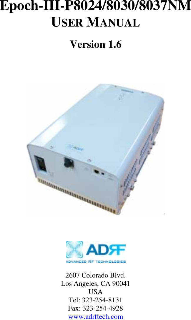
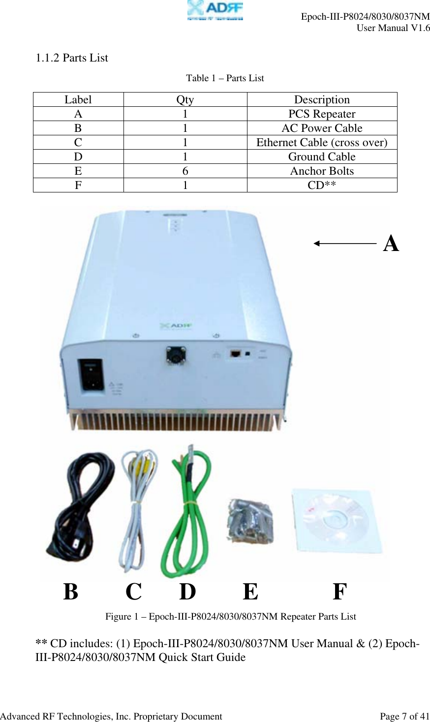
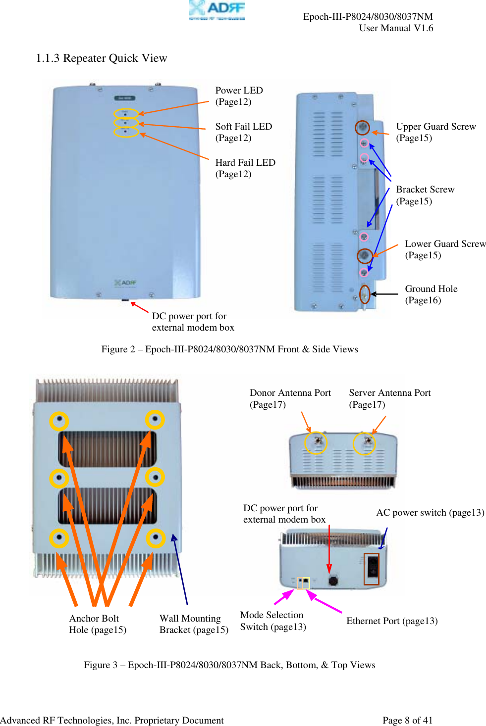
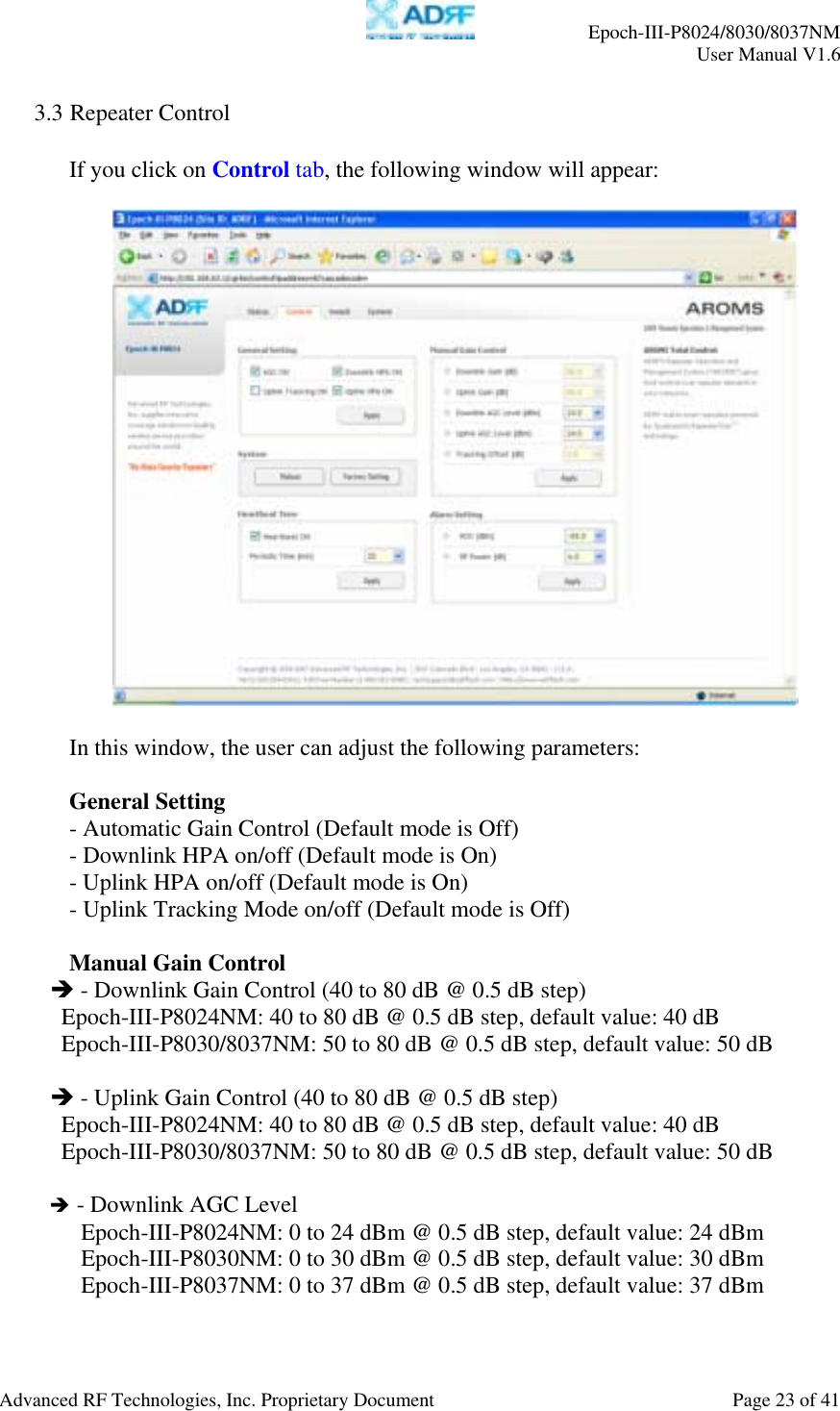
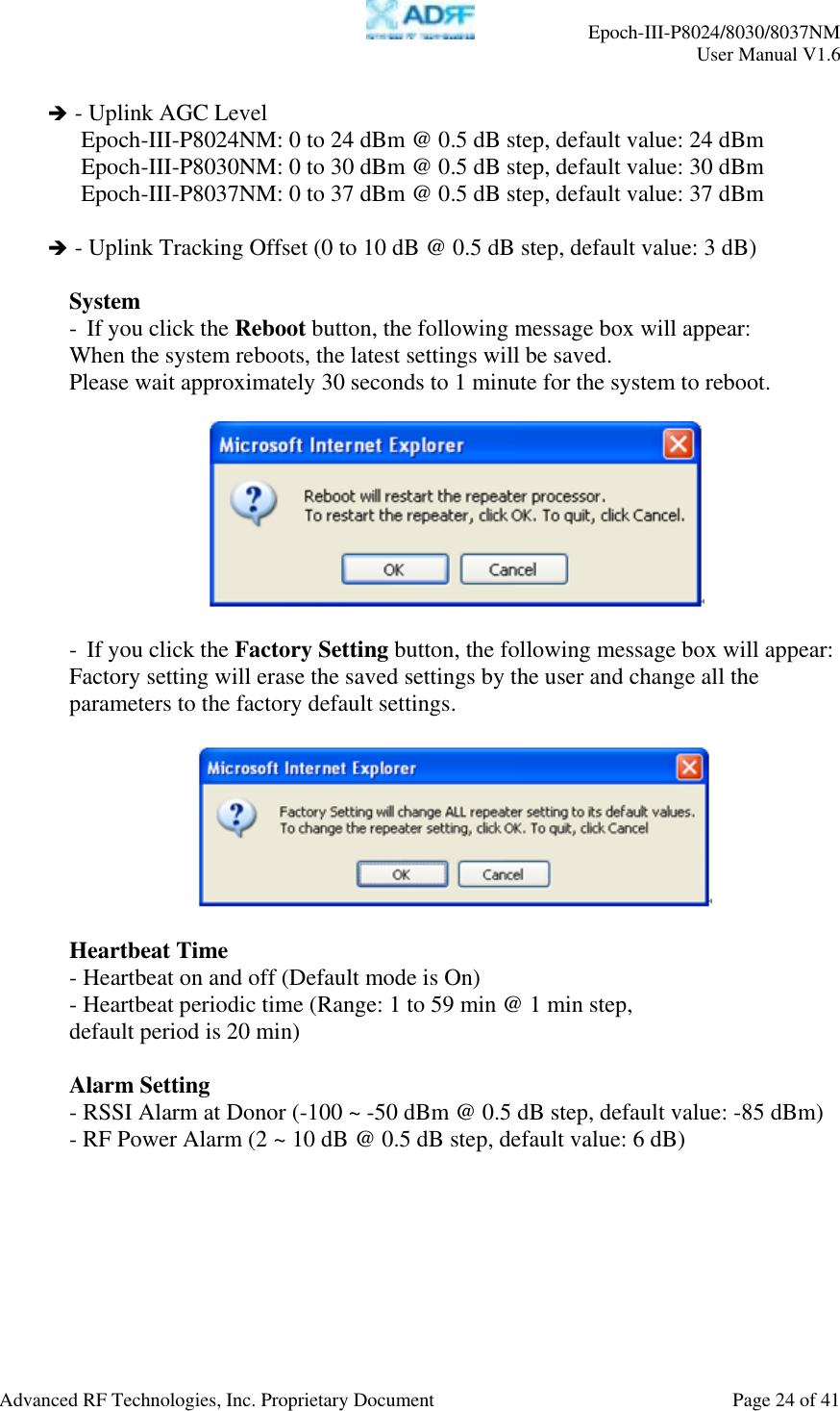
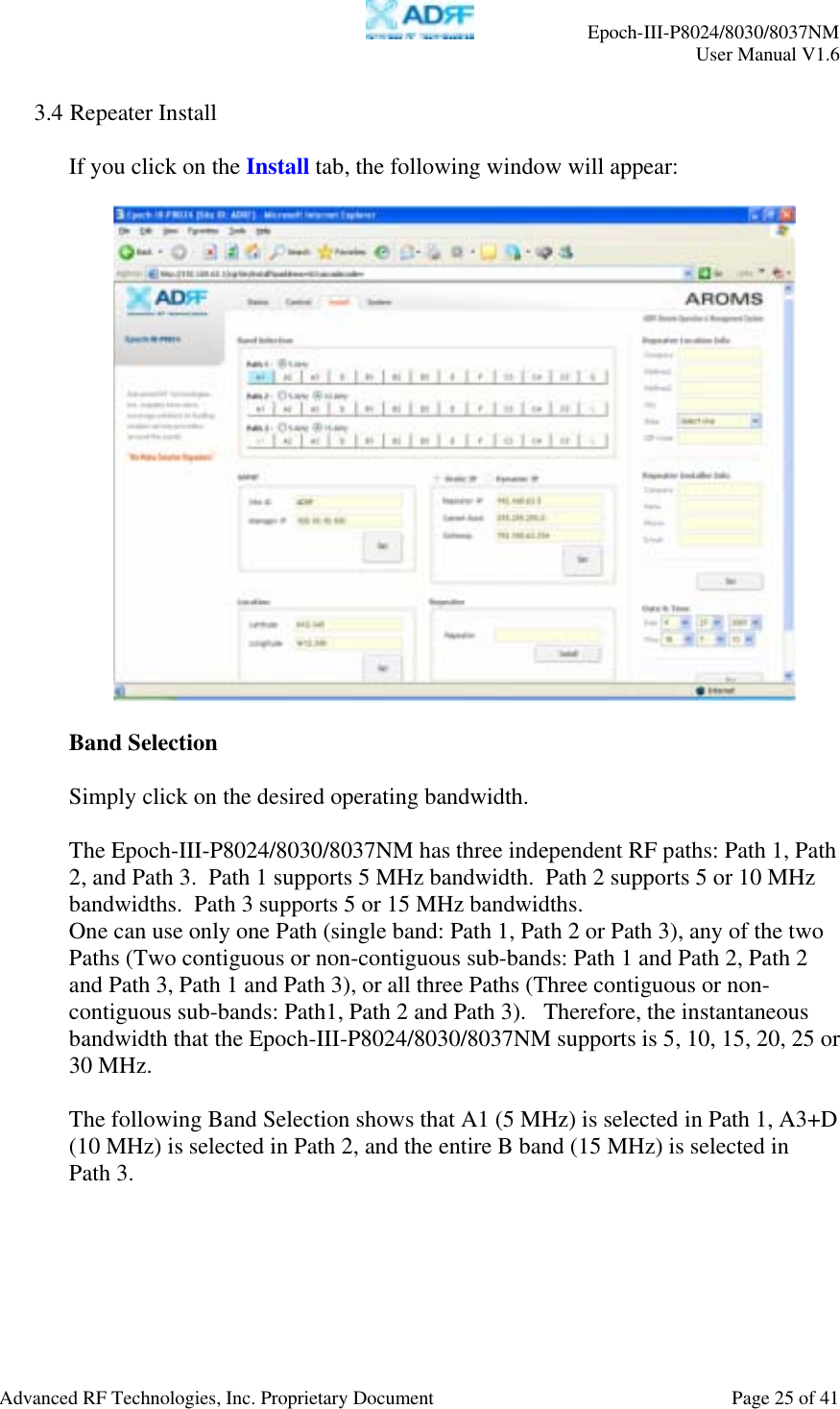
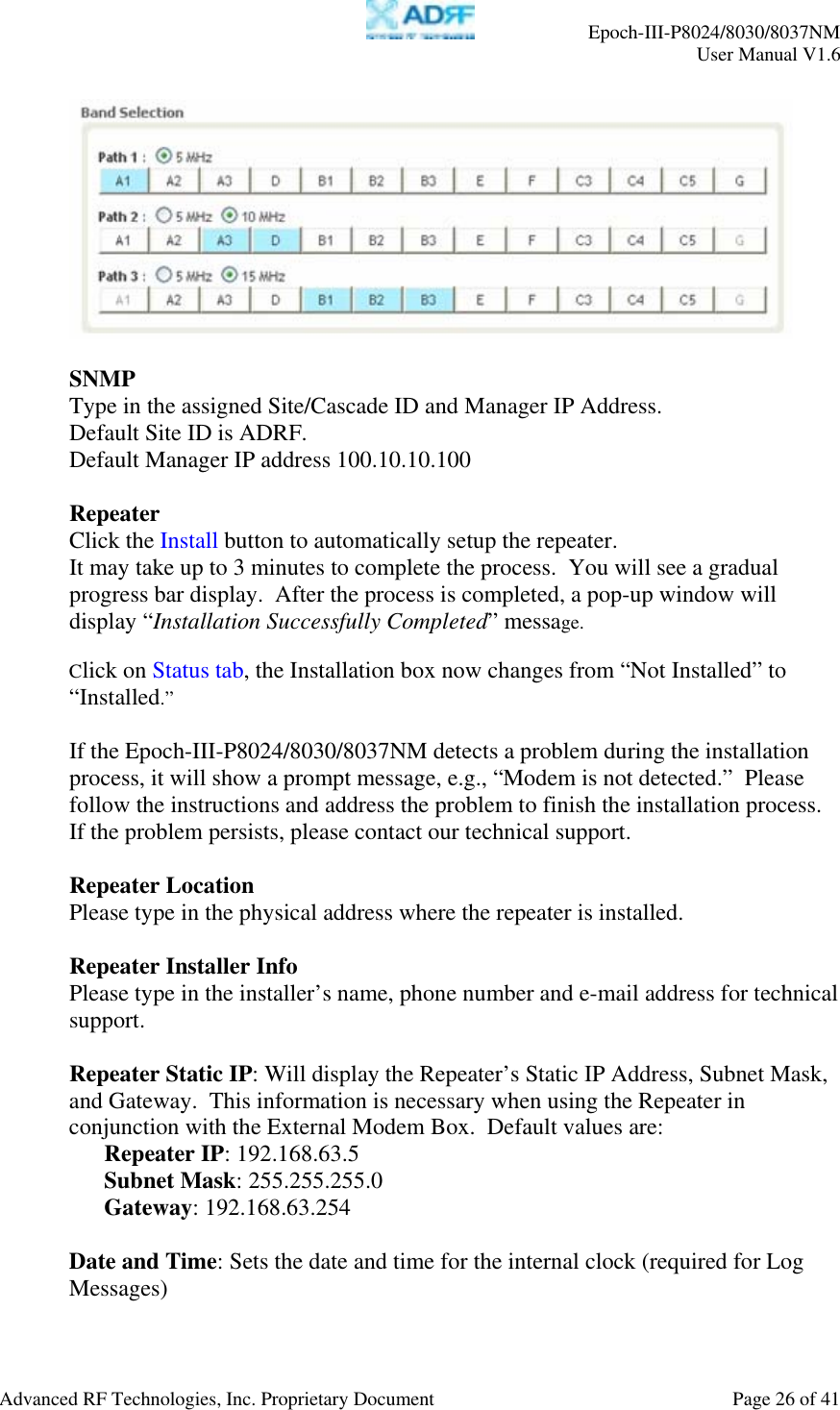
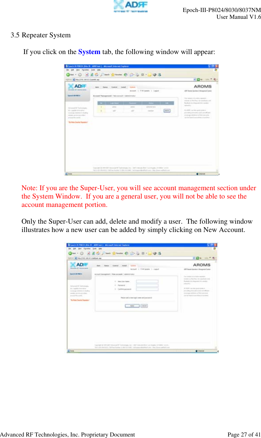
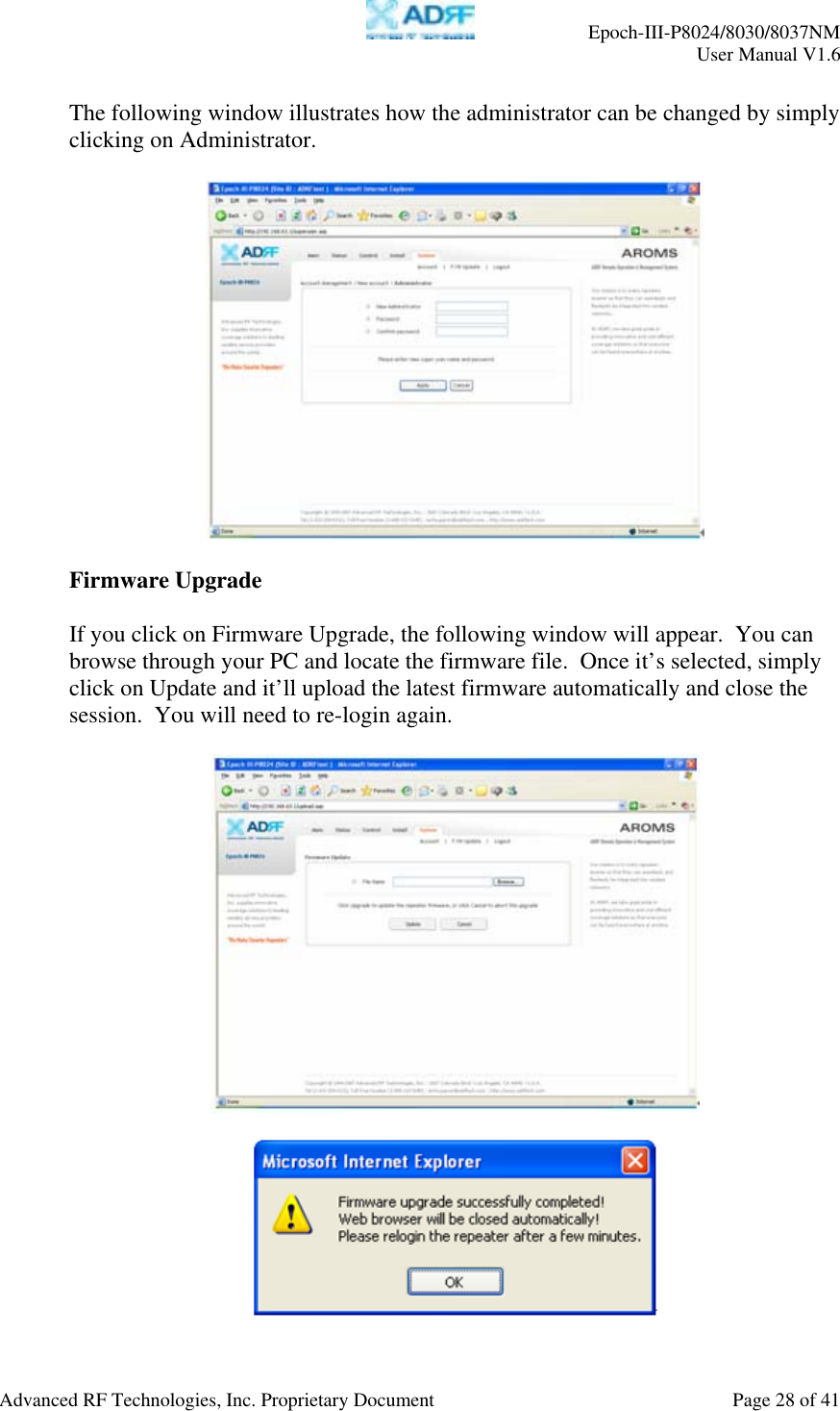
![Epoch-III-P8024/8030/8037NM User Manual V1.6 Advanced RF Technologies, Inc. Proprietary Document Page 6 of 41 1. Epoch-III-P8024/8030/8037NM 1.1 Introduction Epoch-III-P8024/8030/8037NM is a CDMA 1900 MHz RF repeater which enhances in-building wireless coverage in the most effective and cost efficient way. For its intelligent design and versatility, the Epoch-III-P8024/8030/ 8037NM is the ideal choice for wireless coverage problems indoors. Epoch-III-P8024/8030/8037NM can be used as a stand-alone repeater with passive antennas connected to it or it can also be used as a feeder repeater to a DAS (Distributed Antenna System). 1.1.1 Highlights • Covers the 65 MHz PCS band including G band • Supports up to three (3) non-contiguous band combinations • Supports up to six (6) different instantaneous bandwidths; 5, 10, 15, 20, 25 and 30 MHz • 24/30/37 dBm composite output power • 80 dB gain • 40 dB AGC Range @ 0.5 dB Step [Epoch-III-P8024NM] • 30 dB AGC Range @ 0.5 dB Step [Epoch-III-P8030/8037NM] • Sharp out-of-band rejection; 50 dBc @ 1 MHz Sub-band edge • Automated installation • Web GUI via DHCP • Remote Monitoring Capability using External Modem Box (MBOX-DET1)](https://usermanual.wiki/Advanced-RF-Technologies/EPOCHIIIP/User-Guide-931563-Page-6.png)