Advanced RF Technologies EPOCHIIIP Epoch-III-P8024NM, Epoch-III-P8030NM, and Epoch-III-P8037NM repeaters with 5, 10, and 15 MHz filtering (1900 MHz band) User Manual Manual
Advanced RF Technologies, Inc. Epoch-III-P8024NM, Epoch-III-P8030NM, and Epoch-III-P8037NM repeaters with 5, 10, and 15 MHz filtering (1900 MHz band) Manual
Manual
Epoch-III-P8024/8030/8037NM
USER MANUAL
Version 1.6
2607 Colorado Blvd.
Los Angeles, CA 90041
USA
Tel: 323-254-8131
Fax: 323-254-4928
www.adrftech.com

Epoch-III-P8024/8030/8037NM
User Manual V1.6
Advanced RF Technologies, Inc. Proprietary Document Page 2 of 41
Glossary
The following is a list of abbreviations and terms used throughout this
document.
Abbreviation/Term Definition
AGC Automatic Gain Control
ALC Automatic Level Control
AROMS ADRF’s Repeater Operation and Management
System
BTS Base Transceiver Station
CDMA Code Division Multiple Access
CW Continuous Wave (un-modulated signal)
DAS Distributed Antenna System
DL Downlink
Downlink The path covered from the Base Transceiver
Station (BTS) to the subscribers service area
via the repeater
HPA High Power Amplifier
HW Hardware
iDEN Integrated Digital Enhanced Network
IF Intermediate Frequency
LNA Low Noise Amplifier
MS Mobile Station
PLL Phased Locked Loop
PS Power Supply
RF Radio Frequency
SW Software
UL Uplink
Uplink The path covered from the subscribers service
area to the Base Transceiver Station(BTS) via
the repeater
VSWR Voltage Standing Wave Ratio

Epoch-III-P8024/8030/8037NM
User Manual V1.6
Advanced RF Technologies, Inc. Proprietary Document Page 3 of 41
Version 1.6 (Released March 31, 2008)
Information in this document is subject to change without notice.
Advanced RF Technologies, Inc. 1996-2008.
All rights reserved.
Please send comments to:
E-Mail: info@adrftech.com
Phone: (323) 254-8131
(800) 313-9345
Fax: (323) 254-4928
Address: Advanced RF Technologies, Inc.
Attention: Technical Publications Department
2607 Colorado Blvd., 1st Floor
Los Angeles, CA 90041
USA
www.adrftech.com
Revision History
Version Author Description Date
1.0 Peter Son March 15, 2007
1.1 B.C. Kim March 22, 2007
1.2 Julie Song April 2, 2007
1.3 Namchul Lee Update for Epoch-III-P8037NM July 16, 2007
1.4 Namchul Lee Update for UL approval October 17, 2007
1.5 Julie Song Update for external modem box November 18, 2007
1.6 Namchul Lee Update for FCC March 31, 2008

Epoch-III-P8024/8030/8037NM
User Manual V1.6
Advanced RF Technologies, Inc. Proprietary Document Page 4 of 41
TABLE OF CONTENTS
1. EPOCH-III-P8024/8030/8037NM............................................................................. 6
1.1 Introduction ........................................................................................................ 6
1.1.1 Highlights ..................................................................................................... 6
1.1.2 Parts List....................................................................................................... 7
1.1.3 Repeater Quick View.................................................................................... 8
1.2 Warnings and Hazards ........................................................................................... 9
2. EPOCH-III-P8024/8030/8037NM OVERVIEW ................................................... 11
2.1 Operation Modes.............................................................................................. 11
2.1.1. Local Web GUI ......................................................................................... 11
2.1.2. Remote Web GUI...................................................................................... 11
2.2 Switches & Indicators ...................................................................................... 12
2.2.1 LEDs......................................................................................................... 12
2.2.2 AC Power Switch & DC Power Port for External Modem Box.............. 13
2.2.3 Mode Selection Switch and Ethernet Port................................................ 13
2.3 Installation........................................................................................................ 14
2.3.1 Tools......................................................................................................... 14
2.3.2 Procedure.................................................................................................. 14
2.3.3 Grounding................................................................................................. 16
2.3.4 Antenna Separation/Isolation ................................................................... 17
2.3.5 Line of Sight............................................................................................. 18
3. EPOCH-III-P8024/8030/8037NM AROMS SETUP ............................................. 19
3.1 Repeater/PC Connection Using AROMS ............................................................ 19
3.2 Repeater Status..................................................................................................... 21
3.3 Repeater Control .................................................................................................. 23
3.4 Repeater Install..................................................................................................... 25
3.5 Repeater System................................................................................................... 27
4. MAINTENANCE GUIDE FOR EPOCH-III-P8024/8030/8037NM.................... 29
4.1 Periodic Inspection Checklist............................................................................... 29
4.2 Preventive Measures for Optimal Operation........................................................ 29
4.2.1 Recommendations ...................................................................................... 29
4.2.2 Precautions.................................................................................................. 29
5. WARRANTY AND REPAIR POLICY ................................................................. 30
5.1 General Warranty................................................................................................. 30
5.2 Limitations of Warranty....................................................................................... 30
5.3 Limitation of Damages......................................................................................... 30
5.4 No Consequential Damages ................................................................................. 30
5.5 Additional Limitation on Warranty...................................................................... 30
5.6 Return Material Authorization (RMA) ................................................................ 31
APPENDIX A: SPECIFICATIONS.............................................................................. 32
A.1 Electrical Specifications...................................................................................... 32
A.2 Mechanical Specifications................................................................................... 33
A.3 Environmental Specifications.............................................................................. 33
A.4 Power Specifications........................................................................................... 34
A.5 Other Specifications ............................................................................................ 34

Epoch-III-P8024/8030/8037NM
User Manual V1.6
Advanced RF Technologies, Inc. Proprietary Document Page 5 of 41
APPENDIX B: MECHANICAL DRAWING .............................................................. 35
APPENDIX C: EPOCH-III-P8024/8030/8037NM OVERVIEW............................... 38
C.1 Block Diagram..................................................................................................... 38
C.2 Components......................................................................................................... 39

Epoch-III-P8024/8030/8037NM
User Manual V1.6
Advanced RF Technologies, Inc. Proprietary Document Page 6 of 41
1. Epoch-III-P8024/8030/8037NM
1.1 Introduction
Epoch-III-P8024/8030/8037NM is a CDMA 1900 MHz RF repeater which
enhances in-building wireless coverage in the most effective and cost efficient
way. For its intelligent design and versatility, the Epoch-III-P8024/8030/
8037NM is the ideal choice for wireless coverage problems indoors. Epoch-III-
P8024/8030/8037NM can be used as a stand-alone repeater with passive antennas
connected to it or it can also be used as a feeder repeater to a DAS (Distributed
Antenna System).
1.1.1 Highlights
• Covers the 65 MHz PCS band including G band
• Supports up to three (3) non-contiguous band combinations
• Supports up to six (6) different instantaneous bandwidths;
5, 10, 15, 20, 25 and 30 MHz
• 24/30/37 dBm composite output power
• 80 dB gain
• 40 dB AGC Range @ 0.5 dB Step [Epoch-III-P8024NM]
• 30 dB AGC Range @ 0.5 dB Step [Epoch-III-P8030/8037NM]
• Sharp out-of-band rejection; 50 dBc @ 1 MHz Sub-band edge
• Automated installation
• Web GUI via DHCP
• Remote Monitoring Capability using External Modem Box (MBOX-DET1)
Epoch-III-P8024/8030/8037NM
User Manual V1.6
Advanced RF Technologies, Inc. Proprietary Document Page 7 of 41
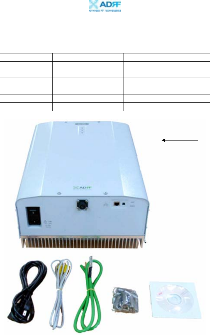
1.1.2 Parts List
Label Qty Description
A 1 PCS Repeater
B 1 AC Power Cable
C 1 Ethernet Cable (cross over)
D 1 Ground Cable
E 6 Anchor Bolts
F 1 CD**
** CD includes: (1) Epoch-III-P8024/8030/8037NM User Manual & (2) Epoch-
III-P8024/8030/8037NM Quick Start Guide
Figure 1 – Epoch-III-P8024/8030/8037NM Repeater Parts List
Table 1 – Parts List
A
B DC E F
Epoch-III-P8024/8030/8037NM
User Manual V1.6
Advanced RF Technologies, Inc. Proprietary Document Page 8 of 41
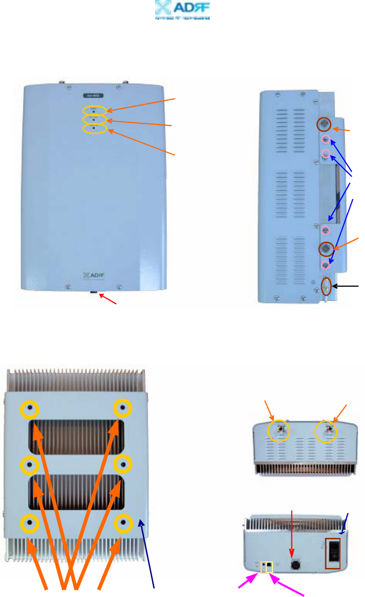
1.1.3 Repeater Quick View
Figure 2 – Epoch-III-P8024/8030/8037NM Front & Side Views
Fi
g
ure 3
–
E
p
och-III-P8024/8030/8037NM Bac
k
,
Botto
m
,
&To
p
Views
Power LED
(Page12)
Soft Fail LED
(Page12)
Hard Fail LED
(Page12)
Upper Guard Screw
(Page15)
Bracket Screw
(Page15)
Lower Guard Screw
(Page15)
Ground Hole
(Page16)
DC power port for
external modem box
Donor Antenna Port
(Page17) Server Antenna Port
(Page17)
Wall Mounting
Bracket (page15)
Anchor Bolt
Hole (page15)
AC power switch (page13)
Mode Selection
Switch (page13) Ethernet Port (page13)
DC power port for
external modem box
Epoch-III-P8024/8030/8037NM
User Manual V1.6
Advanced RF Technologies, Inc. Proprietary Document Page 9 of 41
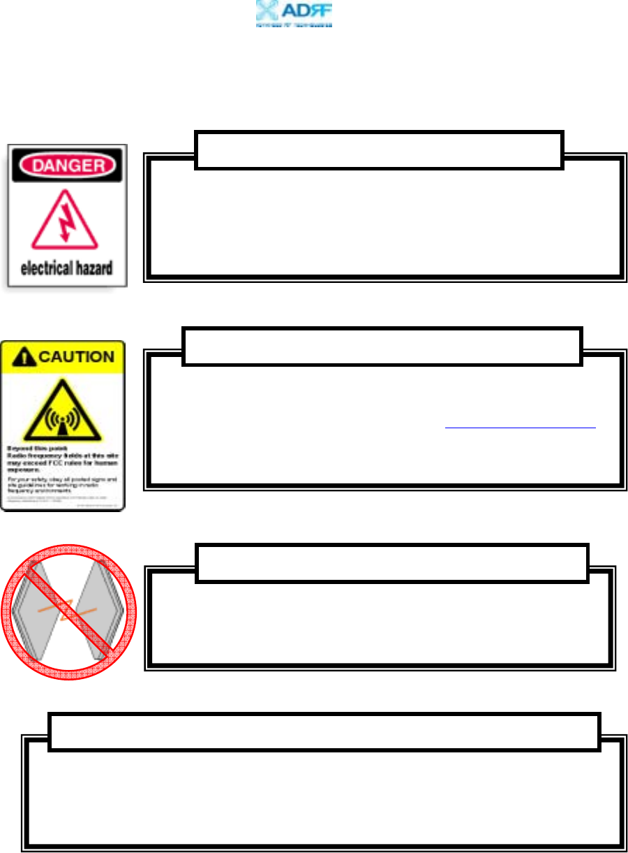
1.2 Warnings and Hazards
Actual separation distance is determined upon gain of antenna used.
Please maintain a minimum safe distance of at least 50 cm while operating near the
donor and the server antennas. Also, the donor antenna needs to be mounted
outdoors on a permanent structure.
RF EXPOSURE & ANTENNA PLACEMENT Guidelines
Operating the Epoch-III-P8024/8030/8037NM with antennas in
very close proximity facing each other could lead to severe
damage to the repeater.
WARNING! DAMAGE TO REPEATER
Working with the repeater while in operation, may expose the
technician to RF electromagnetic fields that exceed FCC rules for
human exposure. Visit the FCC website at www.fcc.gov/oet/rfsafety
to learn more about the effects of exposure to RF electromagnetic
fields.
WARNING! EXPOSURE TO RF
Opening the Epoch-III-P8024/8030/8037NM could result in
electric shock and may cause severe injury.
WARNING! ELECTRIC SHOCK
Epoch-III-P8024/8030/8037NM
User Manual V1.6
Advanced RF Technologies, Inc. Proprietary Document Page 10 of 41
NOTE: This equipment has been tested and found to comply with the limits for a
Class A digital device, pursuant to part 15 of the FCC Rules. These limits are
designed to provide reasonable protection against harmful interference when the
equipment is operated in a commercial environment. This equipment generates,
uses, and can radiate radio frequency energy and, if not installed and used in
accordance with the instruction manual, may cause harmful interference to radio
communications. Operation of this equipment in a residential area is likely to
cause harmful interference in which case the user will be required to correct the
interference at his own expense.
FCC Part 15 Class A
Lithium Battery : CAUTION. RISK OF EXPLOSION IF BATTERY IS REPLACED BY
INCORRECT TYPE. DISPOSE OF USED BATTERIES ACCORDING TO INSTRUCTIONS.
Ethernet Instructions : This equipment is for indoor use only. All cabling should be
limited to inside the building.
Opening or tampering the Epoch-III-P8024/8030/8037NM will void all warranties.
WARRANTY
Epoch-III-P8024/8030/8037NM
User Manual V1.6
Advanced RF Technologies, Inc. Proprietary Document Page 11 of 41
2. Epoch-III-P8024/8030/8037NM Overview
2.1 Operation Modes
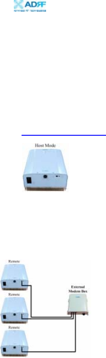
2.1.1. Local Web GUI
Host Mode
This mode should be selected only if an Epoch-III-P8024/8030/8037NM is
used alone without being connected to any other device functioning as a host.
Simply connect one end of the ethernet cable on the repeater monitor port and
the other end on the PC’s LAN port. After doing so, launch the Microsoft
Internet Browser (Internet Explorer) and the Local Web GUI will be launched
through typing the IP address (http://192.168.63.1/home.asp)
2.1.2. Remote Web GUI
Remote Mode
This mode should be selected if an external modem box (MBOX-DET1) is
being installed along with the Epoch-III-P8024/8030/8037NM for monitoring
purposes. In this case, the Epoch-III-P8024/8030/8037NM works as a remote
unit sending its information to the collocated external modem box.
Note: ADRF’s Web GUI has not been developed for Microsoft Internet Explorer and other
web browsers (e.g. Netscape, FireFox, Mozilla, etc.) may not be compatible. ADRF’s Web
GUI has not been tested with Microsoft Internet Explorer versions higher than 6.0.

Epoch-III-P8024/8030/8037NM
User Manual V1.6
Advanced RF Technologies, Inc. Proprietary Document Page 12 of 41
2.2 Switches & Indicators
2.2.1 LEDs
Epoch-III-P8024/8030/8037NM has three LEDs on the front panel of the
repeater as shown below in Figure 4.
POWER
If the LED is lit GREEN, it indicates that there is AC power to the repeater.
SOFT FAIL
If the LED is lit YELLOW, it indicates that there is a soft fail alarm in the
system. The detailed alarm information can be viewed via the local web GUI.
In the event of a soft fail alarm, the repeater will still function, but the alarm
needs to be addressed promptly.
HARD FAIL
If the LED is lit RED, it indicates that there is a hard fail alarm in the system.
The detailed alarm information can be viewed via the local web GUI. In the
event of a hard fail alarm, the repeater will not function and immediate
attention is required.
Figure 4 – Epoch-III-P8024/8030/8037NM Repeater LED View
Epoch-III-P8024/8030/8037NM
User Manual V1.6
Advanced RF Technologies, Inc. Proprietary Document Page 13 of 41
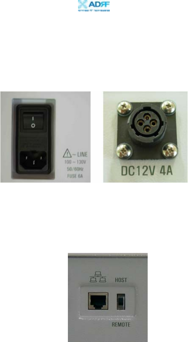
2.2.2 AC Power Switch & DC Power Port for External Modem Box
The AC Power on/off switch is located on the bottom of repeater (Figure 5).
The switch should be powered on after the repeater has been installed properly.
The DC Power Port can be used to provide power to the optional External
Modem Box (Figure 5).
2.2.3 Mode Selection Switch and Ethernet Port
The Ethernet port and the Mode Selection Switch for DHCP are located on
bottom of the repeater as shown below in Figure 6. The mode selection
switch has two modes: Host Mode & Remote Mode.
Fi
g
ure 5
–
AC Power Switch & DC Power Port
Figure 6 – Ethernet Port & Mode Selection Switch

Epoch-III-P8024/8030/8037NM
User Manual V1.6
Advanced RF Technologies, Inc. Proprietary Document Page 14 of 41
2.3 Installation
2.3.1 Tools
No special tools or equipments are needed to install the Epoch-III-
P8024/8030/8037NM.
2.3.2 Procedure
Six mounting holes are located on the wall-mounting bracket to attach it to the
wall. The wall bracket must be securely attached to sufficiently carry the
weight of the Epoch-III-P8024/8030/8037NM, which is bolted to the wall
bracket through the four aligned mounting holes.
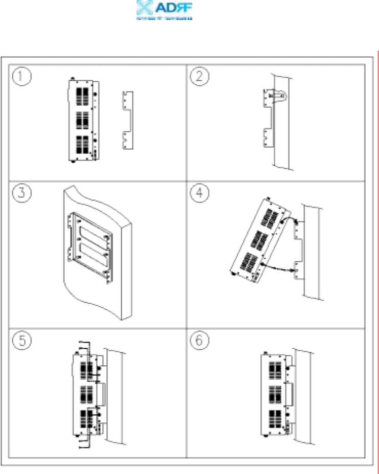
The following steps should be followed while mounting the repeater:
Installation Procedure
① Take the Epoch-III-P8024/8030/8037NM out of the box
② Using the six anchor bolts, mount the bracket on the wall
③ Make sure the bracket is securely mounted
④ Slightly tilt the repeater and mount the repeater onto the wall as shown in
the picture. Hook the upper 2 guard screws first and then slide/push in
the lower 2 guard screws into the place.
⑤ Make sure the Epoch-III-P8024/8030/8037NM is securely placed onto the
wall bracket
⑥ Fasten the 8 bracket screws back properly
⑦ Inspect that everything is secure
* Rack Mount option is also available. Please contact ADRF for additional
information.
Epoch-III-P8024/8030/8037NM
User Manual V1.6
Advanced RF Technologies, Inc. Proprietary Document Page 15 of 41
Figure 7 – Repeater Mounting Instructions
Epoch-III-P8024/8030/8037NM
User Manual V1.6
Advanced RF Technologies, Inc. Proprietary Document Page 16 of 41
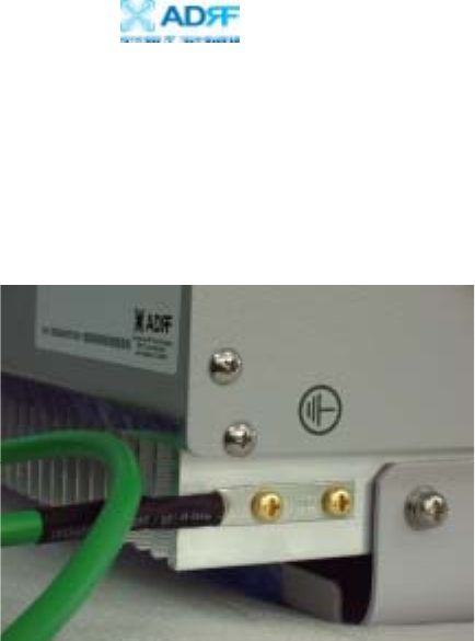
2.3.3 Grounding
A ground cable is included in the packaging and should be properly connected
to the repeater as shown below.
Figure 8 – Ground Cable Connection
Epoch-III-P8024/8030/8037NM
User Manual V1.6
Advanced RF Technologies, Inc. Proprietary Document Page 17 of 41
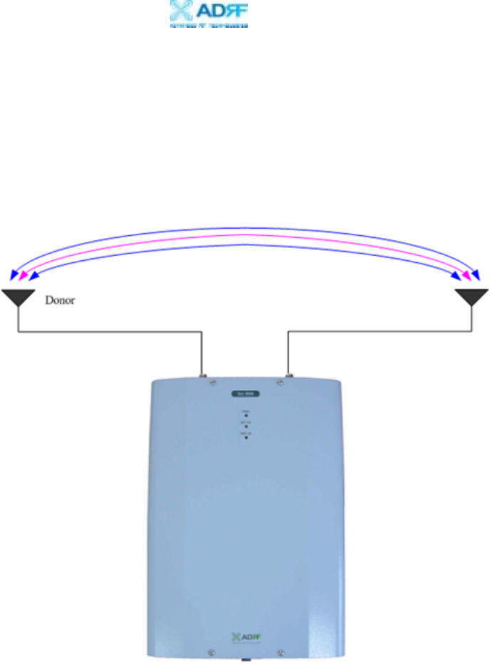
2.3.4 Antenna Separation/Isolation
Separation between the antennas is necessary to prevent oscillation.
Oscillation occurs when the signal entering the system continually reenters,
due to the lack of separation between the donor and server antennas. In other
words, the signal is being fed back into the system. This creates a constant
amplification of the same signal. As a result, the noise level rises above the
signal level.
To prevent feedback, the donor and server antennas must be separated by an
appropriate distance to provide sufficient isolation. Isolation is attained by
separating antennas a sufficient distance so that the output of one antenna does
not reach the input of the other. This distance is dependent on the gain of the
repeater.
A sufficient isolation value is 13 ~ 15 dB greater than the maximum gain of
the repeater. For example, since the Epoch-III-P8030NM has a maximum
gain of 80 dB, it requires an isolation of at least 93 ~ 95 dB.
Figure 9 - RF Repeater Oscillation
Server
Epoch-III-P8024/8030/8037NM
User Manual V1.6
Advanced RF Technologies, Inc. Proprietary Document Page 18 of 41
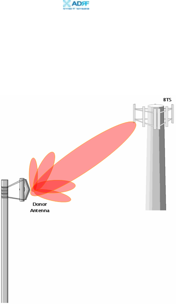
2.3.5 Line of Sight
The donor antenna which points towards the base station typically has a
narrow beam antenna pattern. As a result, a slight deviation away from the
direction of the BTS can lead to less than optimum results. In addition,
obstacles between the repeater and the BTS may impair the repeater from
obtaining any BTS signal. As a result, the repeater cannot transmit signal to
the coverage area. Therefore, a direct line of sight to the BTS for the donor
antenna is vital to the function of a repeater. For the same reason, placing the
server antenna in direct line of sight of the coverage area is also necessary.
Figure 10 - Direct Line of Sight to the BTS
Epoch-III-P8024/8030/8037NM
User Manual V1.6
Advanced RF Technologies, Inc. Proprietary Document Page 19 of 41
3. Epoch-III-P8024/8030/8037NM AROMS Setup
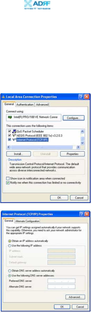
3.1 Repeater/PC Connection Using AROMS
i) Wait until the Power LED is lit in green. Connect the LAN cable between the
laptop’s Ethernet port and the repeater’s Ethernet port.
Note: Under Local Area Connection in Network Settings, make sure to select
Obtain an IP address automatically under Internet Protocol (TCP/IP) properties.
Epoch-III-P8024/8030/8037NM
User Manual V1.6
Advanced RF Technologies, Inc. Proprietary Document Page 20 of 41
ii) Launch MS Internet Explorer (Version 6.0)
Note: ADRF’s Web GUI has not been tested for compatibility with any other web
browsers (e.g. Netscape, FireFox, Mozilla, etc.).
iii) Please type the following IP address into the address bar of MS Internet
Explorer:
http://192.168.63.1/home.asp
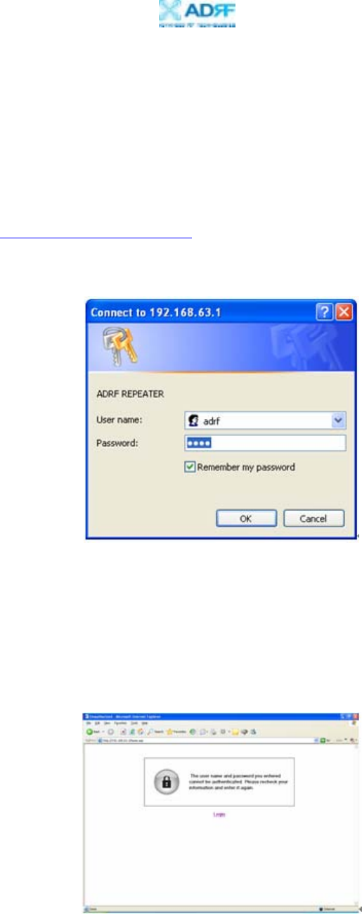
iv) The following login screen will appear:
If you are not the Super-User, please type in your assigned username & password
which you should have received from the Super-User.
The default username and password for the General User is adrf & adrf,
respectively.
If the username & password is typed in incorrectly, the following screen will
appear:
Epoch-III-P8024/8030/8037NM
User Manual V1.6
Advanced RF Technologies, Inc. Proprietary Document Page 21 of 41
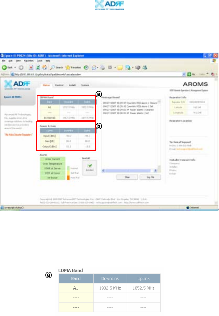
3.2 Repeater Status
If you click on Status tab, the following window will appear:
In this window, the user can view the following:
(To change any parameters, e.g., PCS Sub-Bands, Instantaneous Band
Width, Gain Settings, AGC Level, etc., you must go to the Install or the
Control window.)
- CDMA Band: Will display the center frequencies of the 1900 MHz spectrums
on the downlink and uplink respectively.
Epoch-III-P8024/8030/8037NM
User Manual V1.6
Advanced RF Technologies, Inc. Proprietary Document Page 22 of 41
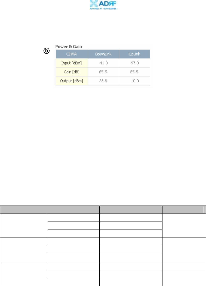
- Power & Gain: Will display the repeater input, gain and output power on the
downlink and uplink.
- Alarm: Will display five alarms with three different status conditions (Normal,
Soft Fail or Hard Fail).
- Message Board: Will show up to recent 20 log messages (Alarms &
Heartbeats).
- Installation: Will display repeater’s installation status (Not Installed or
Installed).
- Repeater Info: Will display repeater’s serial number, and location
information (latitude and longitude coordinates).
- Repeater Location: Will display the address where the repeater is installed
- Technical Support: Will display ADRF’s technical support contact
information.
- Installer Contact Info: Will display the installer’s name, phone and e-mail
address.
Note: Once successfully logged in, the repeater model name and the site/cascade
ID will be displayed on the top of all the windows.
Parameters Range Step Size
Epoch-III-P8024NM -10 ~ 24 dBm
Epoch-III-P8030NM -10 ~ 30 dBm
DL/UL Output Power
Epoch-III-P8037NM -10 ~ 37 dBm
0.1 dB
Epoch-III-P8024NM -12 ~ -97 dBm
Epoch-III-P8030NM -12 ~ -100 dBm
DL/UL Input Power
Epoch-III-P8037NM -12 ~ -100 dBm
0.1 dB
Epoch-III-P8024NM 40 ~ 80 dB 0.5 dB
Epoch-III-P8030NM 50 ~ 80 dB 0.5 dB
Gain
Epoch-III-P8037NM 50 ~ 80 dB 0.5 dB
Epoch-III-P8024/8030/8037NM
User Manual V1.6
Advanced RF Technologies, Inc. Proprietary Document Page 23 of 41
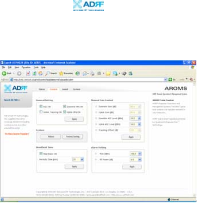
3.3 Repeater Control
If you click on Control tab, the following window will appear:
In this window, the user can adjust the following parameters:
General Setting
- Automatic Gain Control (Default mode is Off)
- Downlink HPA on/off (Default mode is On)
- Uplink HPA on/off (Default mode is On)
- Uplink Tracking Mode on/off (Default mode is Off)
Manual Gain Control
Î - Downlink Gain Control (40 to 80 dB @ 0.5 dB step)
Epoch-III-P8024NM: 40 to 80 dB @ 0.5 dB step, default value: 40 dB
Epoch-III-P8030/8037NM: 50 to 80 dB @ 0.5 dB step, default value: 50 dB
Î - Uplink Gain Control (40 to 80 dB @ 0.5 dB step)
Epoch-III-P8024NM: 40 to 80 dB @ 0.5 dB step, default value: 40 dB
Epoch-III-P8030/8037NM: 50 to 80 dB @ 0.5 dB step, default value: 50 dB
Î - Downlink AGC Level
Epoch-III-P8024NM: 0 to 24 dBm @ 0.5 dB step, default value: 24 dBm
Epoch-III-P8030NM: 0 to 30 dBm @ 0.5 dB step, default value: 30 dBm
Epoch-III-P8037NM: 0 to 37 dBm @ 0.5 dB step, default value: 37 dBm
Epoch-III-P8024/8030/8037NM
User Manual V1.6
Advanced RF Technologies, Inc. Proprietary Document Page 24 of 41
Î - Uplink AGC Level
Epoch-III-P8024NM: 0 to 24 dBm @ 0.5 dB step, default value: 24 dBm
Epoch-III-P8030NM: 0 to 30 dBm @ 0.5 dB step, default value: 30 dBm
Epoch-III-P8037NM: 0 to 37 dBm @ 0.5 dB step, default value: 37 dBm
Î - Uplink Tracking Offset (0 to 10 dB @ 0.5 dB step, default value: 3 dB)
System
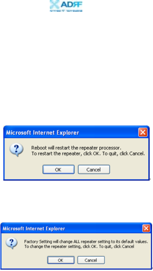
- If you click the Reboot button, the following message box will appear:
When the system reboots, the latest settings will be saved.
Please wait approximately 30 seconds to 1 minute for the system to reboot.
- If you click the Factory Setting button, the following message box will appear:
Factory setting will erase the saved settings by the user and change all the
parameters to the factory default settings.
Heartbeat Time
- Heartbeat on and off (Default mode is On)
- Heartbeat periodic time (Range: 1 to 59 min @ 1 min step,
default period is 20 min)
Alarm Setting
- RSSI Alarm at Donor (-100 ~ -50 dBm @ 0.5 dB step, default value: -85 dBm)
- RF Power Alarm (2 ~ 10 dB @ 0.5 dB step, default value: 6 dB)
Epoch-III-P8024/8030/8037NM
User Manual V1.6
Advanced RF Technologies, Inc. Proprietary Document Page 25 of 41
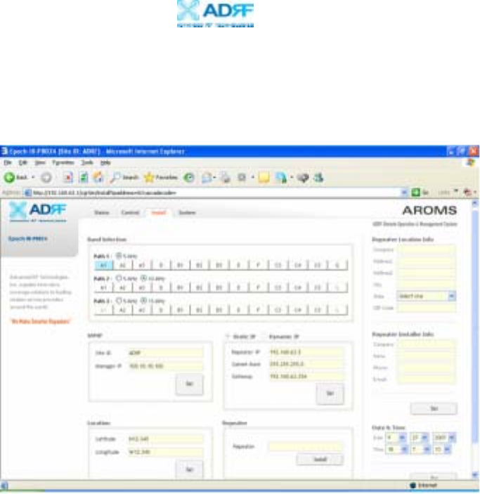
3.4 Repeater Install
If you click on the Install tab, the following window will appear:
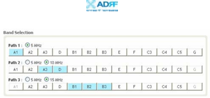
Band Selection
Simply click on the desired operating bandwidth.
The Epoch-III-P8024/8030/8037NM has three independent RF paths: Path 1, Path
2, and Path 3. Path 1 supports 5 MHz bandwidth. Path 2 supports 5 or 10 MHz
bandwidths. Path 3 supports 5 or 15 MHz bandwidths.
One can use only one Path (single band: Path 1, Path 2 or Path 3), any of the two
Paths (Two contiguous or non-contiguous sub-bands: Path 1 and Path 2, Path 2
and Path 3, Path 1 and Path 3), or all three Paths (Three contiguous or non-
contiguous sub-bands: Path1, Path 2 and Path 3). Therefore, the instantaneous
bandwidth that the Epoch-III-P8024/8030/8037NM supports is 5, 10, 15, 20, 25 or
30 MHz.
The following Band Selection shows that A1 (5 MHz) is selected in Path 1, A3+D
(10 MHz) is selected in Path 2, and the entire B band (15 MHz) is selected in
Path 3.
Epoch-III-P8024/8030/8037NM
User Manual V1.6
Advanced RF Technologies, Inc. Proprietary Document Page 26 of 41
SNMP
Type in the assigned Site/Cascade ID and Manager IP Address.
Default Site ID is ADRF.
Default Manager IP address 100.10.10.100
Repeater
Click the Install button to automatically setup the repeater.
It may take up to 3 minutes to complete the process. You will see a gradual
progress bar display. After the process is completed, a pop-up window will
display “Installation Successfully Completed” message.
Click on Status tab, the Installation box now changes from “Not Installed” to
“Installed.”
If the Epoch-III-P8024/8030/8037NM detects a problem during the installation
process, it will show a prompt message, e.g., “Modem is not detected.” Please
follow the instructions and address the problem to finish the installation process.
If the problem persists, please contact our technical support.
Repeater Location
Please type in the physical address where the repeater is installed.
Repeater Installer Info
Please type in the installer’s name, phone number and e-mail address for technical
support.
Repeater Static IP: Will display the Repeater’s Static IP Address, Subnet Mask,
and Gateway. This information is necessary when using the Repeater in
conjunction with the External Modem Box. Default values are:
Repeater IP: 192.168.63.5
Subnet Mask: 255.255.255.0
Gateway: 192.168.63.254
Date and Time: Sets the date and time for the internal clock (required for Log
Messages)
Epoch-III-P8024/8030/8037NM
User Manual V1.6
Advanced RF Technologies, Inc. Proprietary Document Page 27 of 41
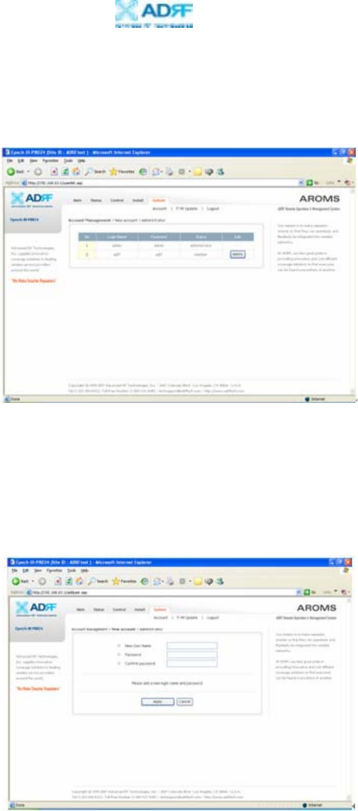
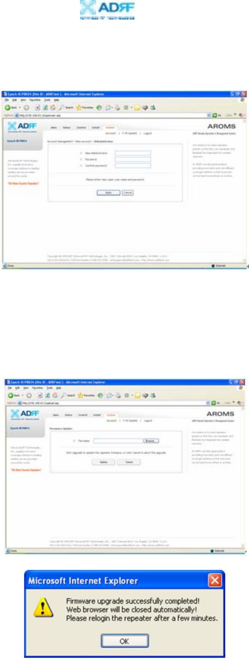
3.5 Repeater System
If you click on the System tab, the following window will appear:
Note: If you are the Super-User, you will see account management section under
the System Window. If you are a general user, you will not be able to see the
account management portion.
Only the Super-User can add, delete and modify a user. The following window
illustrates how a new user can be added by simply clicking on New Account.
Epoch-III-P8024/8030/8037NM
User Manual V1.6
Advanced RF Technologies, Inc. Proprietary Document Page 28 of 41
The following window illustrates how the administrator can be changed by simply
clicking on Administrator.
Firmware Upgrade
If you click on Firmware Upgrade, the following window will appear. You can
browse through your PC and locate the firmware file. Once it’s selected, simply
click on Update and it’ll upload the latest firmware automatically and close the
session. You will need to re-login again.

Epoch-III-P8024/8030/8037NM
User Manual V1.6
Advanced RF Technologies, Inc. Proprietary Document Page 29 of 41
4. Maintenance Guide for Epoch-III-P8024/8030/8037NM
4.1 Periodic Inspection Checklist
4.1.1 Check for loose connections to the repeater and antennas. If connections
are loose, make sure that all connections are tightly fastened properly.
4.1.2 Check that cables and connectors are in good condition.
4.1.3 Ensure that the repeater brackets are in good condition and that the
repeater is securely fastened.
4.2 Preventive Measures for Optimal Operation
4.2.1 Recommendations
1.1.3.1 Perform the Periodic Inspection Checklist quarterly or
semiannually.
4.2.2 Precautions
• Do not operate the repeater with the antennas in extremely close proximity
as this may cause damage to the repeater.
• Do not change parameters unless instructed to do so by an authorized
supervisor.
• Do not move the repeater unless instructed to do so by an authorized
supervisor.
• Do not detach any cables to the repeater unless repair of respective
components are necessary.

Epoch-III-P8024/8030/8037NM
User Manual V1.6
Advanced RF Technologies, Inc. Proprietary Document Page 30 of 41
5. Warranty and Repair Policy
5.1 General Warranty
The Epoch-III-P8024/8030/8037NM carries a Standard Warranty period of five
(5) years unless indicated otherwise on the package or in the acknowledgment of
the purchase order.
5.2 Limitations of Warranty
Your exclusive remedy for any defective product is limited to the repair or
replacement of the defective product. Advanced RF Technologies, Inc. may elect
which remedy or combination of remedies to provide in its sole discretion.
Advanced RF Technologies, Inc. shall have a reasonable time after determining
that a defective product exists to repair or replace the problem unit. Advanced RF
Technologies, Inc. warranty applies to repaired or replaced products for the
balance of the applicable period of the original warranty or ninety days from the
date of shipment of a repaired or replaced product, whichever is longer.
5.3 Limitation of Damages
The liability for any defective product shall in no event exceed the purchase price
for the defective product.
5.4 No Consequential Damages
Advanced RF Technologies, Inc. has no liability for general, consequential,
incidental or special damages.
5.5 Additional Limitation on Warranty
Advanced RF Technologies, Inc. standard warranty does not cover products which
have been received improperly packaged, altered, or physically damaged. For
example, broken warranty seal, labels exhibiting tampering, physically abused
enclosure, broken pins on connectors, any modifications made without Advanced
RF Technologies, Inc. authorization, will void all warranty.

Epoch-III-P8024/8030/8037NM
User Manual V1.6
Advanced RF Technologies, Inc. Proprietary Document Page 31 of 41
5.6 Return Material Authorization (RMA)
No product may be returned directly to Advanced RF Technologies, Inc. without
first getting an approval from Advanced RF Technologies, Inc. If it is determined
that the product may be defective, you will be given an RMA number and
instructions in how to return the product. An unauthorized return, i.e., one for
which an RMA number has not been issued, will be returned to you at your
expense. Authorized returns are to be shipped to the address on the RMA in an
approved shipping container. You will be given our courier information. It is
suggested that the original box and packaging materials should be kept if an
occasion arises where a defective product needs to be shipped back to Advanced
RF Technologies, Inc. To request an RMA, please call (323) 254-8131 or send an
email to techsupport@adrftech.com.

Epoch-III-P8024/8030/8037NM
User Manual V1.6
Advanced RF Technologies, Inc. Proprietary Document Page 32 of 41
Appendix A: Specifications
A.1 Electrical Specifications
Parameters Specifications Comments
Downlink 1930~1995 MHz
Frequency Range Uplink 1850~1915 MHz
Frequency Error ≤ ± 0.05 ppm
Band Selection 5/10 MHz + 5/15 MHz + 5 MHz
Full band ≤ ±1.25 dB
Gain Flatness Each band ≤ ±1.25 dB
Maximum 80 dB
Step 0.5 dB
P8024NM 40 dB
Range P8030NM/P8037NM 30 dB
Gain
Tolerance ≤ ±0.5 dB
P8024NM +24 dBm
P8030NM +30 dBm
Composite
Output Power
(UL/DL) P8037NM +37 dBm
AGC Error ≤ ±0.5 dB
≥ 45 dBc/30 kHz @ fo ± 885 KHz
≥ 50 dBc/30 kHz @ fo ± 1.98 MHz
Inband Spurious emissions
≤ -13 dBm/1 MHz @ fo ± 2.25 MHz
≤ -13 dBm/1 kHz; 9 kHz < f < 150 kHz
≤ -13 dBm/10 kHz; 150 kHz < f < 30 MHz
≤ -13 dBm/100 kHz; 30 MHz < f < 1 GHz
Outband Spurious emissions
≤ -13 dBm /1 MHz; 1 GHz < f < 5 GHz
Roll offs > 50 dBc @1 MHz outside passband
P8024NM ≤ 5.0 dB@ max gain
P8030NM ≤ 5.0 dB@ max gain
Noise Figure
(Uplink)
P8037NM ≤ 5.0 dB@ max gain
Delay ≤ 5 us
VSWR ≤ 1.5:1
Coupling for Modem 15 ± 2 dB
Epoch-III-P8024/8030/8037NM
User Manual V1.6
Advanced RF Technologies, Inc. Proprietary Document Page 33 of 41
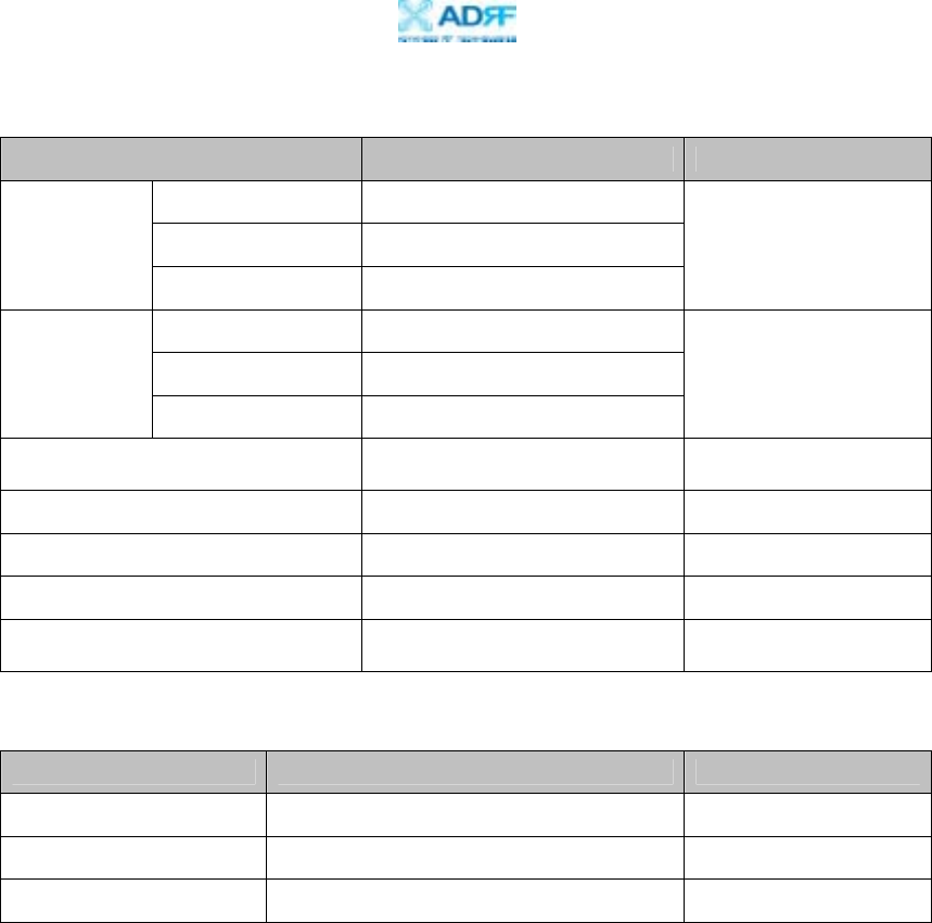
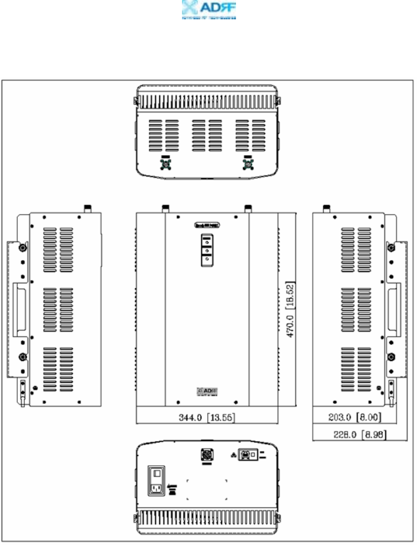
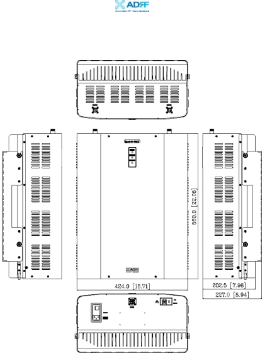
A.2 Mechanical Specifications
Parameters Specifications Comments
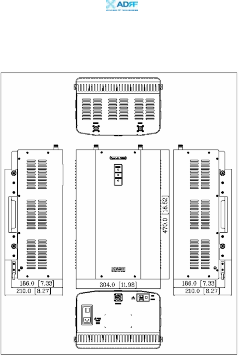
Epoch-III-P8024NM 11.98 x 18.52 x 7.33 inches
Epoch-III-P8030NM 13.55 x 18.52 x 8.00 inches
Dimension
Epoch-III-P8037NM 16.71 x 22.06 x 7.96 inches
Bracket excluded
Epoch-III-P8024NM 40.82 lbs
Epoch-III-P8030NM 44.00 lbs
Weight
Epoch-III-P8037NM 62.83 lbs
Bracket excluded
RF Ports N-Type (F) Donor & Server Antenna
Ports
Local Interface RJ45 (DHCP)
Cooling Air Convection
IP Class IP 20 Indoor Type
Mounting Type Wall Mounting 19” Rack Mounting
Option Available
A.3 Environmental Specifications
Parameters Specifications Comments
Operating Temperature -10 ~ +50 ℃ Ambient
Relative Humidity 5 ~ 95 %, (Non-Condensing)
Dust Industrial Dust Per Telcordia GR63 Core
Epoch-III-P8024/8030/8037NM
User Manual V1.6
Advanced RF Technologies, Inc. Proprietary Document Page 34 of 41
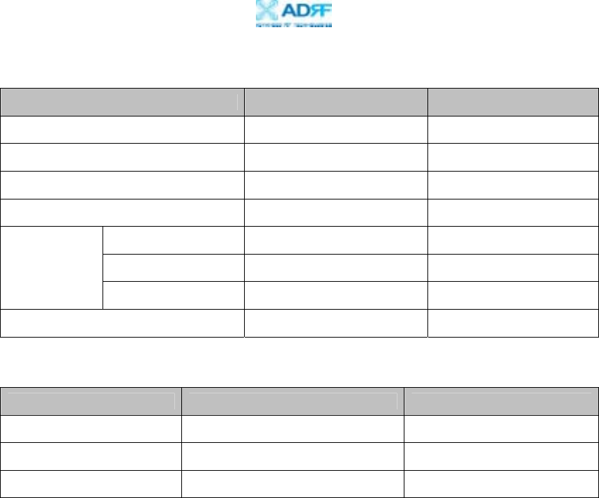
A.4 Power Specifications
Parameters Specifications Comments
AC Power 100 ~ 130 AC
AC Frequency 50 ~ 60 Hz
AC Supply Protection Fuse
DC Power Option -40 ~ -60 V / +20 ~ 30 V
Epoch-III-P8024NM ≤ 95 W
Epoch-III-P8030NM ≤ 150 W
Power
Consumption
Epoch-III-P8037NM ≤ 250 W
Ground External Threaded Stud
A.5 Other Specifications
Parameters Specifications Comments
MTBF > 100,000 Hours
Certificates UL 60950, FCC Part 15, 24
Warranty 5 Years
Epoch-III-P8024/8030/8037NM
User Manual V1.6
Advanced RF Technologies, Inc. Proprietary Document Page 35 of 41
Appendix B: Mechanical Drawing
Epoch-III-P8024NM
Epoch-III-P8024/8030/8037NM
User Manual V1.6
Advanced RF Technologies, Inc. Proprietary Document Page 36 of 41
Epoch-III-P8030NM
Epoch-III-P8024/8030/8037NM
User Manual V1.6
Advanced RF Technologies, Inc. Proprietary Document Page 37 of 41
Epoch-III-P8037NM
Epoch-III-P8024/8030/8037NM
User Manual V1.6
Advanced RF Technologies, Inc. Proprietary Document Page 38 of 41
Appendix C: Epoch-III-P8024/8030/8037NM Overview
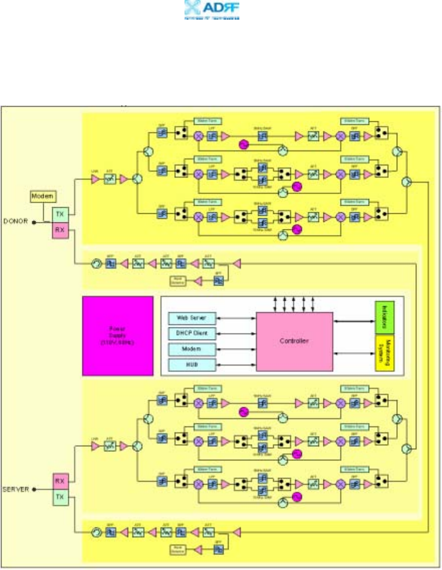
C.1 Block Diagram
Epoch-III-P8024/8030/8037NM Repeater Block Diagram
Epoch-III-P8024/8030/8037NM
User Manual V1.6
Advanced RF Technologies, Inc. Proprietary Document Page 39 of 41
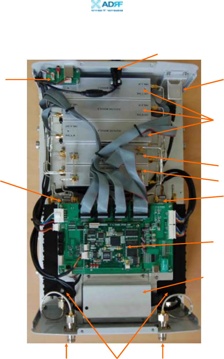
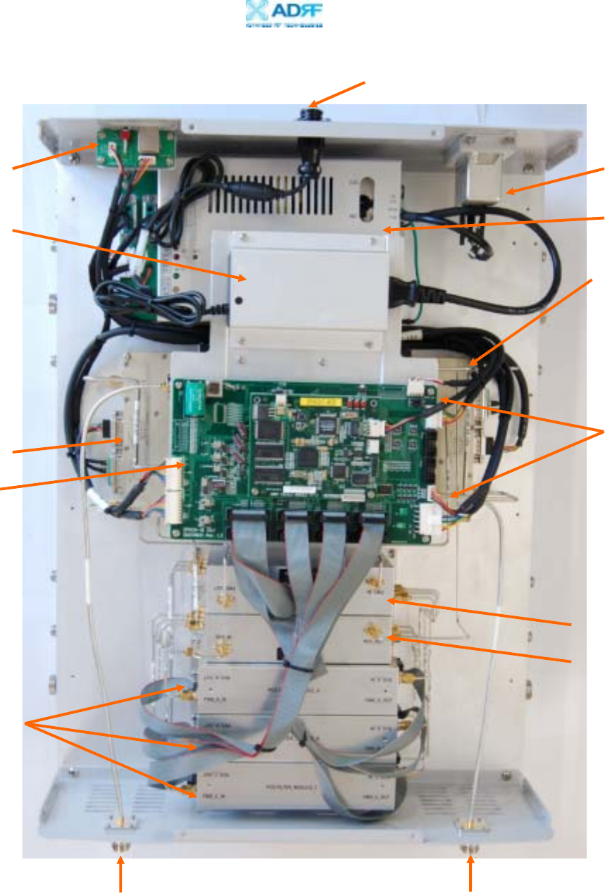
C.2 Components
Epoch-III-P8024/8030NM:
Duplexer Donor Port Server Port
DHCP Sub Board Noise Filter
Adapter for modem box
Control Board
Downlink UDC
Uplink UDC
UP/Down Converter
Uplink HPA
Modem box Port
Downlink HPA
Epoch-III-P8024/8030NM Internal Components
Epoch-III-P8024/8030/8037NM
User Manual V1.6
Advanced RF Technologies, Inc. Proprietary Document Page 40 of 41
Epoch-III-P8037NM:
Epoch-III-P8037NM Internal Components
Duplexer
Donor Port Server Port
DHCP Sub Board Noise Filter
Adapter for modem box
Control Board
Downlink UDC
Uplink UDC
UP/Down Converter
Uplink HPA
Modem box Port
Downlink HPA
Power Supply

Epoch-III-P8024/8030/8037NM
User Manual V1.6
Advanced RF Technologies, Inc. Proprietary Document Page 41 of 41
Power Supply
It provides DC power to each module within the repeater.
Controller
It is responsible for monitoring the status of each module and controls the
parameters. Also it interfaces with PC through Ethernet port.
Down Converter Module
The downlink RF signal that enters through the cavity filter is converted to IF
frequency, which is later converted back to RF frequency through SAW filtering.
Up Converter Module
The uplink RF signal that enters through the cavity filter is converted to IF
frequency, which is later converted back to RF frequency through SAW filtering.
Duplexer
It consists of two BPFs (band-pass filters): PCS TX (1930 ~ 1995 MHz) & RX
(1850 ~ 1915 MHz)
HPA
It receives the output signal from the Up/Down converter module and amplifies
the signal to the repeater’s rated maximum power level.
Modem Box Adapter
Adapter for modem box