Advanced RF Technologies PSR78 IDEN Band Repeater User Manual Verizon Wireless ADRF 25K
Advanced RF Technologies, Inc. IDEN Band Repeater Verizon Wireless ADRF 25K
UserManual.wiki
>
Advanced RF Technologies
>
PSR78 User Manual
User manual
Navigation menu
Upload a User Manual
Namespaces
Wiki Guide
HTML
PDF
Info
Views
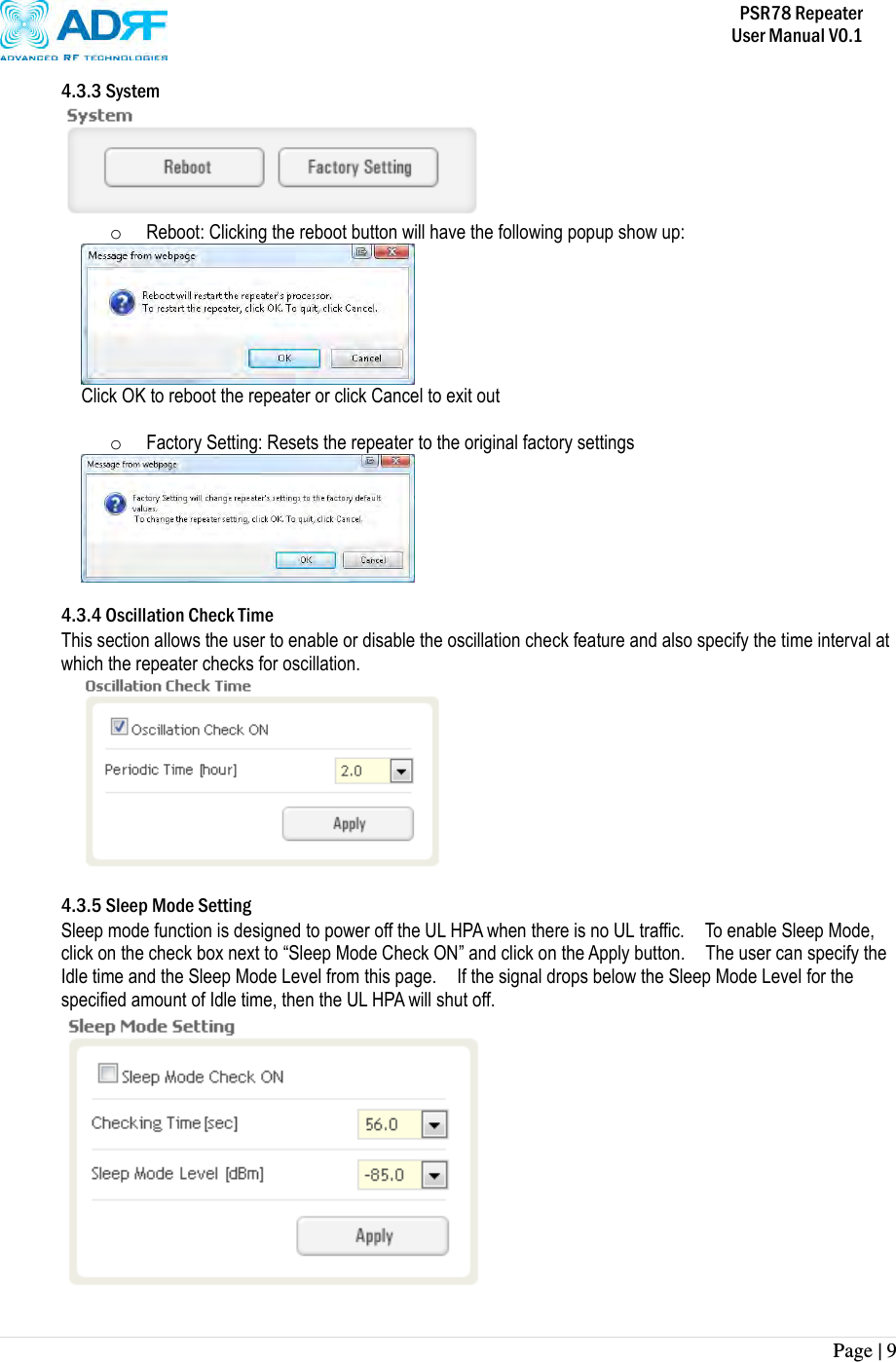
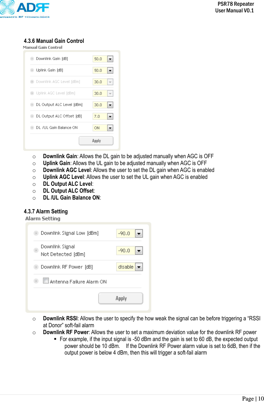
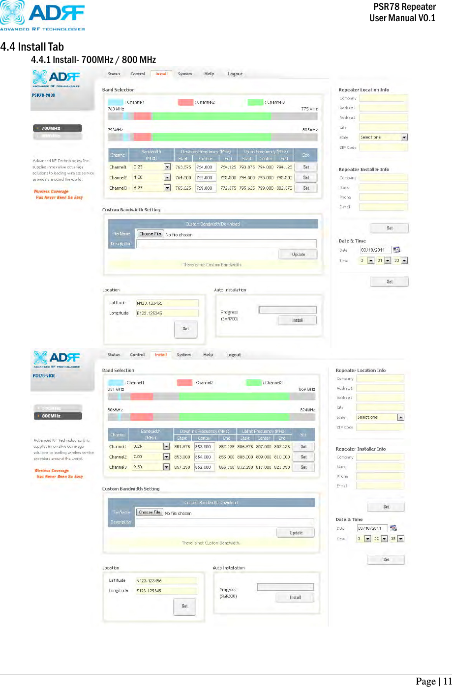
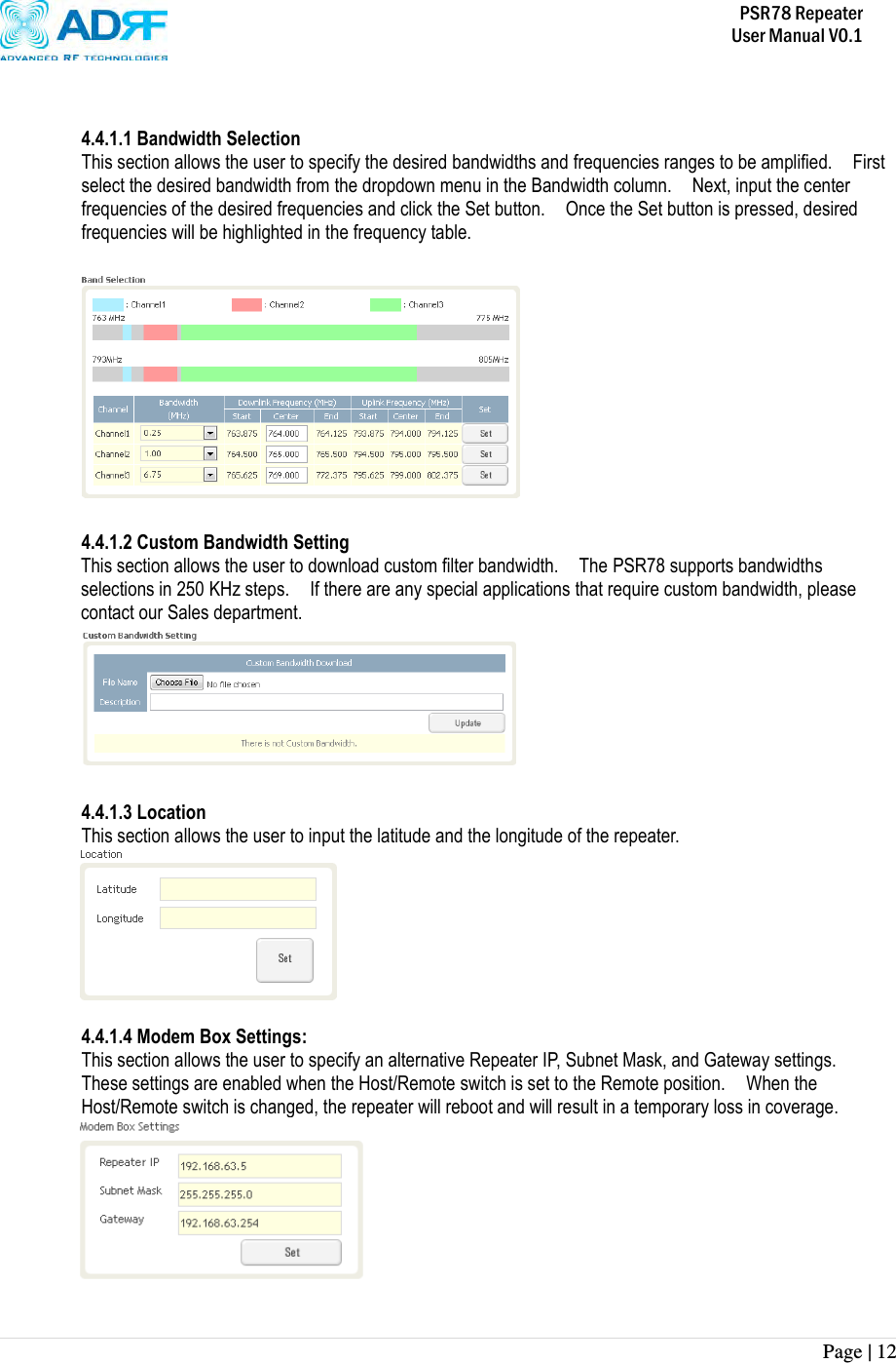
User Manual
Discussion / Help
Navigation