Advanced RF Technologies PSR78 IDEN Band Repeater User Manual Verizon Wireless ADRF 25K
Advanced RF Technologies, Inc. IDEN Band Repeater Verizon Wireless ADRF 25K
User manual

PSR78 Repeater
User Manual V0.1
Page | 2
Glossary
The following is a list of abbreviations and terms used throughout this document.
Abbreviation/Term
Definition
AGC
Automatic Gain Control
ALC
Automatic Level Control
AROMS
ADRF’ Repeater Operation and Management
System
BTS
Base Transceiver Station
CDMA
Code Division Multiple Access
CFE
Compact Front End
CW
Continuous Wave (un-modulated signal)
DAS
Distributed Antenna System
DL
Downlink
Downlink
The path covered from the Base Transceiver
Station (BTS) to the subscribers service area via
the repeater
HPA
High Power Amplifier
HW
Hardware
IF
Intermediate Frequency
LNA
LTE
Low Noise Amplifier
Long Term Evolution
MS
Mobile Station
PLL
Phased Locked Loop
PS
Power Supply
RF
Radio Frequency
SQE
Signal Quality Estimate
SW
Software
UL
Uplink
Uplink
The path covered from the subscribers service
area to the Base Transceiver Station(BTS) via the
repeater
VSWR
Voltage Standing Wave Ratio
PSR78 Repeater
User Manual V0.1
Page | 3
Released version: 0.1
Information in this document is subject to change without notice.
Advanced RF Technologies, Inc. 1996-2011.
All rights reserved.
Please send comments to:
E-Mail: info@adrftech.com
Phone: (818) 840-8131
(800) 313-9345
Fax: (818) 840-8138
Address: Advanced RF Technologies, Inc.
Attention: Technical Publications Department
3116 Vanowen St.
Burbank, CA 91505
USA
www.adrftech.com
Revision History
Version
Author
Description
Date
0.1
Sun Kim
Initial Release
March 16, 2011

PSR78 Repeater
User Manual V0.1
Page | 4
TABLE OF CONTENTS
1. PSR78 REPEATER .......................................................................................................... 6
1.1 Introduction ................................................................................................................ 6
1.1.1 Highlights ......................................................................................................... 6
1.1.2 Parts List ........................................................................................................... 7
1.1.3 Repeater Quick View........................................................................................ 7
2. WARNINGS AND HAZARDS ........................................................................................ 9
3. PSR78 OVERVIEW ....................................................................................................... 11
3.1 Switches & Fault Indicators ..................................................................................... 11
3.1.1 LEDs............................................................................................................... 11
3.1.2 Message Board Alarms and Notification ....................................................... 11
3.2 Switches and Ports ................................................................................................... 12
3.2.1 AC In Port....................................................................................................... 12
3.2.2 Battery Port .................................................................................................... 12
3.2.3 Power Switch.................................................................................................. 12
3.2.3 Ethernet Port and Host/Remote Switch .......................................................... 13
3.2.4 RF Ports .......................................................................................................... 13
3.2.5 Ext. ALARM Port .......................................................................................... 13
3.5 Installation ............................................................................................................... 14
3.5.1 Wall Mount Procedure .................................................................................... 14
3.5.3 Grounding......................................................................................................... 1
3.5.4 Antenna Separation/Isolation ........................................................................... 2
3.5.5 Line of Sight ..................................................................................................... 3
4. PSR78 WEB-GUI SETUP ................................................................................................ 4
4.1 Repeater/PC Connection Using Web-GUI ................................................................. 4
4.2 Status Tab ................................................................................................................... 5
4.2.1 Status- 700 MHz ............................................................................................... 5
4.2.2 Status- 800 MHz ............................................................................................... 5
4.2.3 Side Navigation Bar ......................................................................................... 6
4.2.4 SMR700 Band / SMR800 Band ....................................................................... 6
4.2.5 Power & Gain ................................................................................................... 6
4.2.6 Alarm ................................................................................................................ 6
4.2.7 AAI ................................................................................................................... 7
4.2.8 Message Board ................................................................................................. 7
4.2.9 Repeater Info / Modem Info / Technical Support / Installer Contact Info ....... 7
4.2.10 Install, Modem, and Power Status .................................................................. 8
4.3 Control Tab ................................................................................................................ 8
4.3.1 Control .............................................................................................................. 8
4.3.2 General Setting ................................................................................................. 8
4.3.3 System .............................................................................................................. 9
4.3.4 Oscillation Check Time .................................................................................... 9
4.3.5 Sleep Mode Setting .......................................................................................... 9

PSR78 Repeater
User Manual V0.1
Page | 5
4.4 Install Tab ................................................................................................................. 11
4.4.1 Install- 700MHz / 800 MHz ........................................................................... 11
4.5 System ...................................................................................................................... 13
4.5.1 System: Account ............................................................................................. 13
4.5.2 System: User Log ........................................................................................... 15
4.5.3 System: Update .............................................................................................. 15
4.6 Help .......................................................................................................................... 16
4.7 Logout ...................................................................................................................... 16
Clicking the Logout button will log the current user off the system. ............................ 16
5. MAINTENANCE GUIDE FOR PSR78 REPEATER ................................................. 17
5.1 Periodic Inspection Checklist .................................................................................. 17
5.2 Preventive Measures for Optimal Operation ........................................................... 17
5.2.1 Recommendations .......................................................................................... 17
5.2.2 Precautions ..................................................................................................... 17
6. WARRANTY AND REPAIR POLICY ......................................................................... 18
6.1 General Warranty ..................................................................................................... 18
6.2 Limitations of Warranty ........................................................................................... 18
6.3 Limitation of Damages ............................................................................................ 18
6.4 No Consequential Damages ..................................................................................... 18
6.5 Additional Limitation on Warranty .......................................................................... 18
6.6 Return Material Authorization (RMA) .................................................................... 18
7. SPECIFICATIONS ........................................................................................................ 19
7.1 Electrical Specifications .......................................................................................... 19
7.2 Mechanical Specifications ....................................................................................... 20
7.3 Power Specifications ................................................................................................ 20
7.4 Environment Specifications ..................................................................................... 20
7.5 Alarm Specification ................................................................................................. 21
APPENDIX A: MECHANICAL DRAWING ................................................................... 22
APPENDIX B: SHUTDOWN RETRY LOGIC ............................................................... 23

PSR78 Repeater
User Manual V0.1
Page | 6
1. PSR78 Repeater
1.1 Introduction
The PSR78 is an over-the-air repeater system that operates in both the 700 and 800 MHz public safety
frequencies.
1.1.1 Highlights
• Supports up to 2 frequency bands simultaneously
o Covers the entire 700 MHz Public Safety Frequencies (12 MHz)
o Covers the entire 800 MHz Public Safety Frequencies (18 MHz)
• Composite Output Power of 30 dBm
• 30 dB AGC Range @ 0.5 dB Step
• Adjustable AGC Output Power Level
• Adjustable ALC Level
• Band Selectable via Web-GUI
• Can Support up to 6 total Non-Contiguous Bands
• External Alarming capabilities via dry contact AAI alarms
• Digital filtering
• Incremental Automatic Shutdown/Resumption Time: PSR78 gradually increases the time span between
automatic shutdown and resumption before it permanently shuts itself down
• Versatility and Usability: PSR78 gives total control to the user. Most of the control parameters, e.g., gain,
output power, alarm threshold, etc. can be changed using the Web-GUI so that the user can adjust the
system perfectly to the given RF environment
• Web-GUI connectivity via DHCP
• Supports DHCP; No 3rd party GUI software required
• Automated installation
PSR78 Repeater
User Manual V0.1
Page | 7
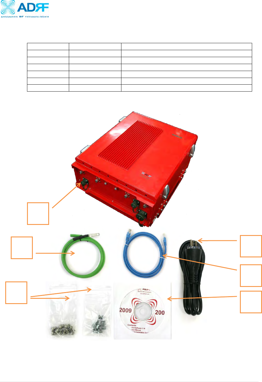
1.1.2 Parts List
Label
Quantity
Description
A
1
PSR78 Repeater
C
1
AC Power Cable
D
1
Ethernet Cable (Crossover)
E
1
Documentation CD**
F
1
Ground Cable
G
8
Rack Mount Bolt/Nut
** CD includes: User Manual, Quick-Start Guide, and Troubleshooting Guide
Figure A – PSR78 Repeater Parts List
Table 1 – Parts List
A
C
D
E
F
G
PSR78 Repeater
User Manual V0.1
Page | 8
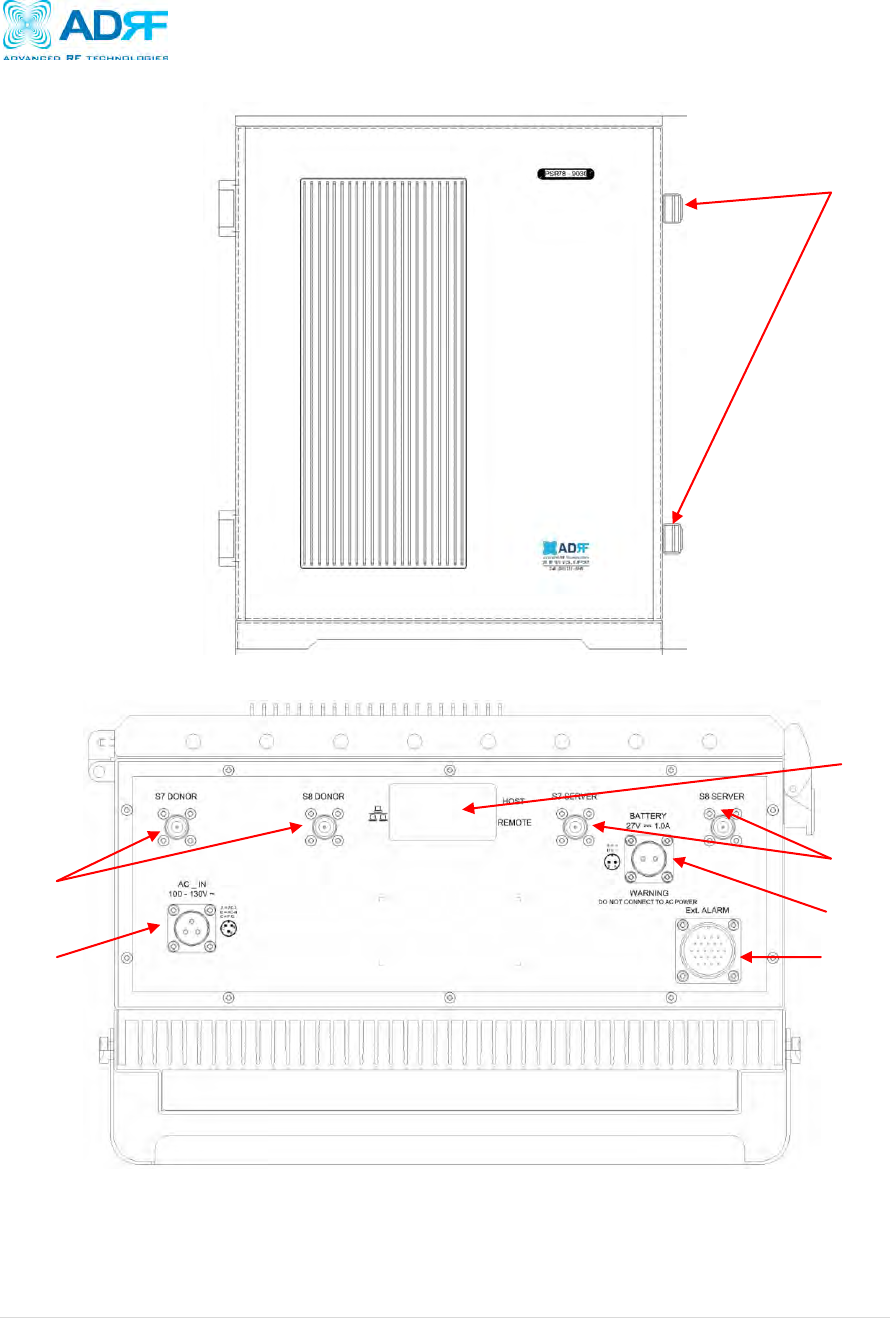
1.1.3 Repeater Quick View
Door Latches
AC IN Port
External AAI Alarm Port
Battery Backup Port
RJ-45 Port and
Host/Remote Switch
Server Ports
Donor Ports
PSR78 Repeater
User Manual V0.1
Page | 9
2. Warnings and Hazards
Actual separation distance is determined upon gain of antenna used.
Please maintain a minimum safe distance of at least 50 cm while operating near the donor and the server antennas. Also, the donor
antenna needs to be mounted outdoors on a permanent structure.
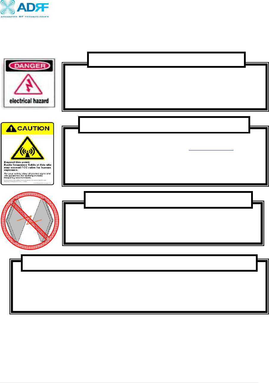
RF EXPOSURE & ANTENNA PLACEMENT Guidelines
Operating the Axiom with antennas in very close proximity facing each other could lead to severe
damage to the repeater.
WARNING! DAMAGE TO REPEATER
Working with the repeater while in operation, may expose the technician to RF electromagnetic fields that
exceed FCC rules for human exposure. Visit the FCC website at www.fcc.gov/oet/rfsafety to learn
more about the effects of exposure to RF electromagnetic fields.
WARNING! EXPOSURE TO RF
Opening the PSR78 could result in electric shock and may cause severe injury.
WARNING! ELECTRIC SHOCK
PSR78 Repeater
User Manual V0.1
Page | 10
Double Pole/Neutral Fusing.
CAUTION
NOTE: This equipment has been tested and found to comply with the limits for a Class A digital device,
pursuant to part 15 of the FCC Rules. These limits are designed to provide reasonable protection
against harmful interference when the equipment is operated in a commercial environment. This
equipment generates, uses, and can radiate radio frequency energy and, if not installed and used in
accordance with the instruction manual, may cause harmful interference to radio communications.
Operation of this equipment in a residential area is likely to cause harmful interference in which case
the user will be required to correct the interference at their own expense.
FCC Part 15 Class A
Lithium Battery: CAUTION. RISK OF EXPLOSION IF BATTERY IS REPLACED BY INCORRECT TYPE.
DISPOSE OF USED BATTERIES ACCORDING TO INSTRUCTIONS.
Ethernet Instructions: This equipment is for indoor use only. All cabling should be limited to inside the
building.
Opening or tampering the Axiom will void all warranties.
WARRANTY
PSR78 Repeater
User Manual V0.1
Page | 11
3. PSR78 Overview
3.1 Switches & Fault Indicators
3.1.1 LEDs
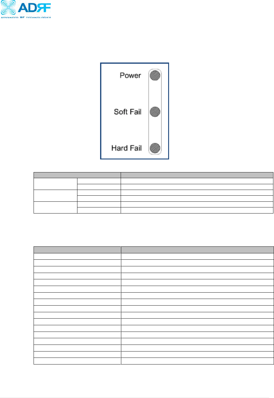
The PSR78 has 3 LED’s located on inside of the repeater.
Figure 1: Module LED
PSR78
Specifications
Power
Solid Green
Module power is ON
OFF
Module is powered OFF
Soft Fail
Solid Yellow
Soft Fail alarm exist in the system
OFF
No Soft Fail alarm are present in the system
Hard Fail
Solid Red
Hard Fail alarm exist in the system
OFF
No Hard Fail alarms are present in the system
3.1.2 Message Board Alarms and Notification
Parameters
Remark
AC fail
Power supply out of range
DC fail
Power supply out of range
Communication failure
Internal Communication failure
RMF
Field replaceable module failure
RESET
Reset alarm
Heartbeat
Heartbeat
OSC
Oscillation detected
UL RSSI fail
Power at coverage port too high
UL PLL fail
UL Synthesizer failure
H/W fail
Hardware failure
S/W fail
Software failure
UL Emission fail
UL Out-of-band emissions out of spec
DL RSSI fail
Donor Power too high/low
ISO fail
Low isolation
DL PLL fail
DL Synthesizer failure
DL Spur fail
DL Spurious emissions out of spec
Interfere
Interferer power exceeded
PSR78 Repeater
User Manual V0.1
Page | 12
3.2 Switches and Ports
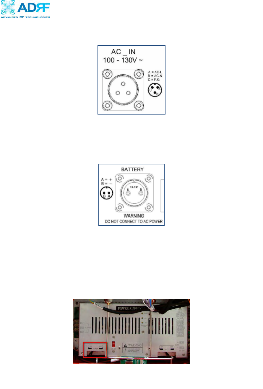
3.2.1 AC In Port
The AC In Port is designed to work with the power cable that is included with the system.
Figure 2: AC In Port
3.2.2 Battery Port
The PSR78 can be connected to an ADRF-BBU (ADRF Battery Backup) to provide power during a power failure.
If an ADRF-BBU is utilized, connect the ADRF-BBU to the PSR78 via the external battery port as shown in Figure
4.
Figure 3: Battery Backup Port
(WARNING: The circuit switch on the ADRF-BBU must be set to OFF before connecting the ADRF-BBU
to the PSR78 to prevent damage to the repeater or the ADRF-BBU and personal injury.)
Note: Please contact ADRF Technical Support for assistance if you are unfamiliar with the installation
procedure of our battery box.
3.2.3 Power Switch
The power switch is located on the inside of the repeater. Open the 2 latches on the side of the repeater to
open the top cover. Once opened, the power switch is located on the bottom left of the power supply.
Figure 4: Battery Backup Port
PSR78 Repeater
User Manual V0.1
Page | 13
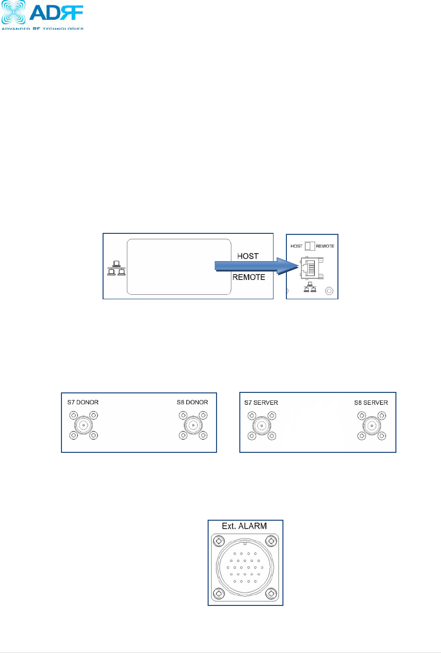
3.2.3 Ethernet Port and Host/Remote Switch
The Ethernet Port and Host/Remote switch are located underneath the waterproof cover. Loosen the hand-
screws and remove the cover to expose the Host/Remote switch and the Ethernet port to gain access to the
system. Once the system is configured, it is recommended replace the cover and tighten the screws back into
place.
Ethernet Port
The Ethernet port can be used to communicate directly with the PSR78 using a RJ-45 crossover cable or can
also be used to connect the PSR78 to an external modem box.
Host/Remote Switch
The Host/Remote Switch allows the user to switch the default Repeater IP, Subnet Mask, and Gateway of the
repeater to an alternative setup. These settings can be adjusting by logging into the repeater in HOST mode
and configuring the settings under the Modem Box Setting section on the Install Page (section 4.4). Once
the settings are set, flipping the switch to the REMOTE position will reboot the repeater with the new alternate
settings. Please note that when the repeater is set to the REMOTE position DHCP is disabled and the
repeater will not automatically assign an IP address to any device that connects directly to the repeater.
Figure 4: Ethernet Port and Host/Remote Switch
3.2.4 RF Ports
The donor and server antennas connect directly to the PSR78 using the ports listed below:
S7 DONOR- 700 MHz Donor Antenna
S8 DONOR- 800 MHz Donor Antenna
S7 SERVER- 700 MHz Server Antenna
S8 SERVER- 800 MHz Server Antennas
Figure 5: PSR78 RF Ports
3.2.5 Ext. ALARM Port
The PSR78 uses the open collector method. The Ext. Alarm port allows the PSR78 to send out dry contact AAI
alarms to an alarming panel. The PSR78 can receive a voltage up to +24V on the “+” line.
Figure 6: Ext. ALARM Port
PSR78 Repeater
User Manual V0.1
Page | 14
3.5 Installation
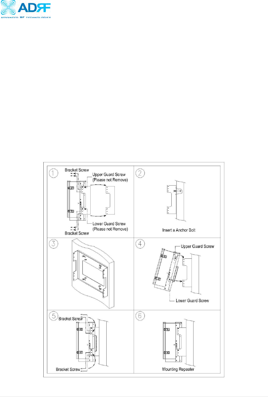
3.5.1 Wall Mount Procedure
The wall-mounting bracket has six mounting holes which are used to mount the bracket to the wall. The wall
bracket must be securely attached to the wall in order to support the weight of the PSR78. After mounting the
bracket to the wall, the PSR78 is placed on the mounting bracket using the four guard screws attached to the
PSR78.
The following steps should be followed while mounting the repeater:
① Take the PSR78 out of the box.
② Using the six anchor bolts, mount the bracket on the wall.
③ Make sure the bracket is securely mounted.
④ Slightly tilt the top portion of the repeater and mount the repeater onto the wall as shown in figure 4 in
the illustrations below. Hook the upper 2 guard screws first and then slide/push in the lower 2
guard screws into place.
⑤ Make sure the PSR78 is securely placed onto the wall bracket.
⑥ Fasten the 8 bracket screws back properly on both sides.
⑦ Verify that the repeater is secure and properly grounded.
Figure 7: Wall Mount Instructions
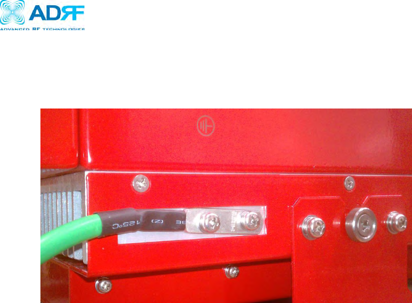
3.5.3 Grounding
Install the ground cable which is included in the package on the side of the repeater as show in the figure below.
Figure 8: Wall Mount Instructions
PSR78 Repeater
User Manual V0.1
Page | 2
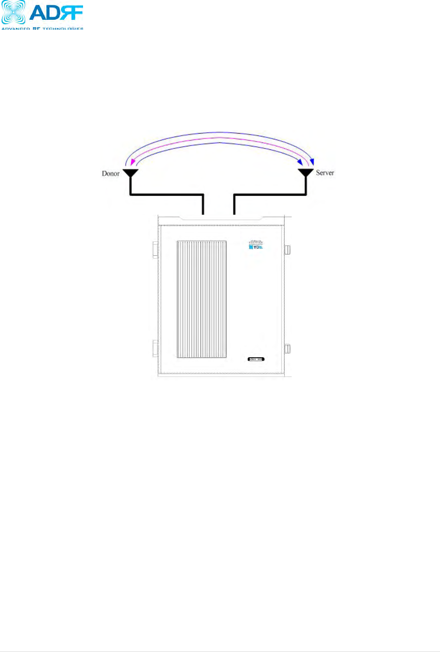
3.5.4 Antenna Separation/Isolation
Separation between the antennas is necessary to prevent oscillation. Oscillation occurs when the signal entering the
system continually reenters, due to the lack of separation between the donor and server antennas. In other words,
the signal is being fed back into the system. This creates a constant amplification of the same signal. As a result,
the noise level rises above the signal level.
REPEATER
Figure 9: RF Repeater Oscillation
To prevent feedback, the donor and server antennas must be separated by an appropriate distance to provide
sufficient isolation. Isolation is attained by separating antennas a sufficient distance so that the output of one
antenna does not reach the input of the other. This distance is dependent on the gain of the repeater.
A sufficient isolation value is 13 ~ 15 dB greater than the maximum gain of the repeater. For example, if the gain of
the repeater is 50 dB, then an isolation of 63 ~ 65 dB or greater is required. In the same manner, because the
PSR78 has a maximum gain of 90 dB, it requires an isolation of at least 103 ~ 105 dB.
PSR78 Repeater
User Manual V0.1
Page | 3
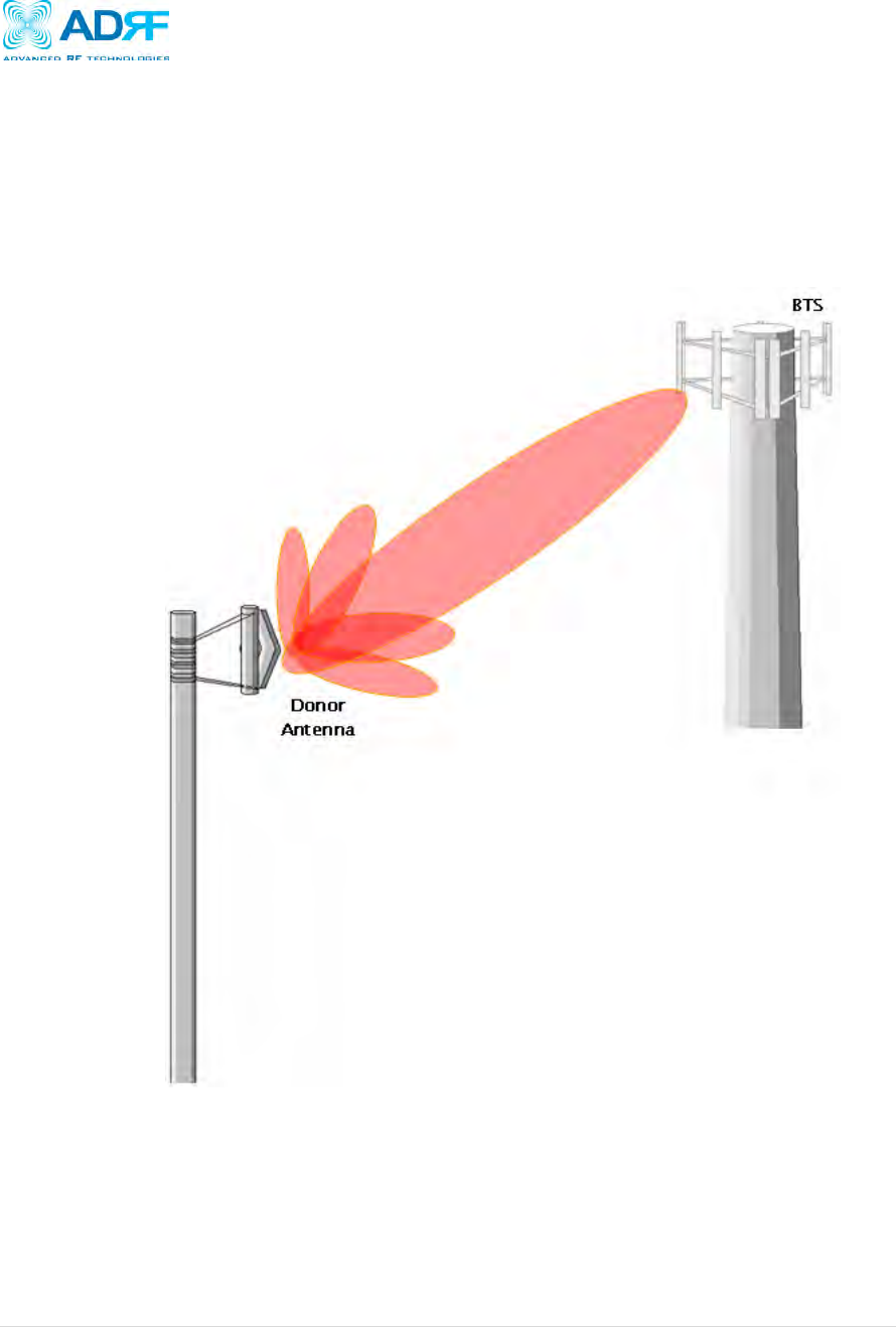
3.5.5 Line of Sight
The donor antenna which points towards the base station typically has a narrow beam antenna pattern. As a
result, a slight deviation away from the direction of the BTS can lead to less than optimum results. In addition,
obstacles between the repeater and the BTS may impair the repeater from obtaining any BTS signal. As a result,
the repeater cannot transmit signal to the coverage area. Therefore, a direct line of sight to the BTS for the donor
antenna is vital to the function of a repeater. For the same reason, placing the server antenna in direct line of
sight of the coverage area is also necessary.
Figure 10 - Direct Line of Sight to the BTS
PSR78 Repeater
User Manual V0.1
Page | 4
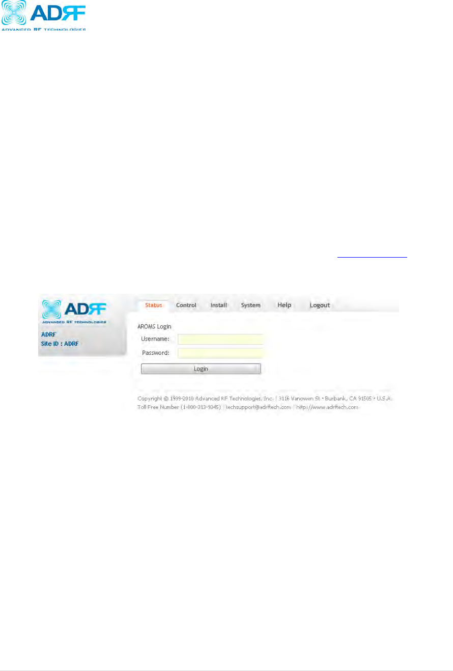
4. PSR78 Web-GUI Setup
The Web-GUI allows the user to communicate with the repeater either locally or remotely. To connect to the repeater
locally, you will need a laptop with an Ethernet port and a RJ-45 crossover cable. To connect to the repeater remotely,
you will need to have an active internet connection and the repeater must have either an internal modem or an Omnibox
(ADRF Modem Box) connected to the repeater.
4.1 Repeater/PC Connection Using Web-GUI
A. Verify that your Local Area Connection is set to Obtain an IP address automatically under the Internet Protocol
(TCP/IP) properties
If you are connecting to the unit remotely, then skip steps A and B.
B. Connect the RJ-45 crossover cable between the laptop’s Ethernet port and the repeater’s Ethernet port
C. Launch an Internet Browser
D. Type the following IP address into the address bar of Microsoft Internet Explorer: http://192.168.63.1
If you are connecting to the unit remotely, then type the IP address of the modem to connect to the unit
E. The following login screen will appear:
If you are not the Administrator, please type in your assigned username & password which you should have
received from the Administrator.
The default username and password for the General User is adrf & adrf, respectively.
PSR78 Repeater
User Manual V0.1
Page | 5
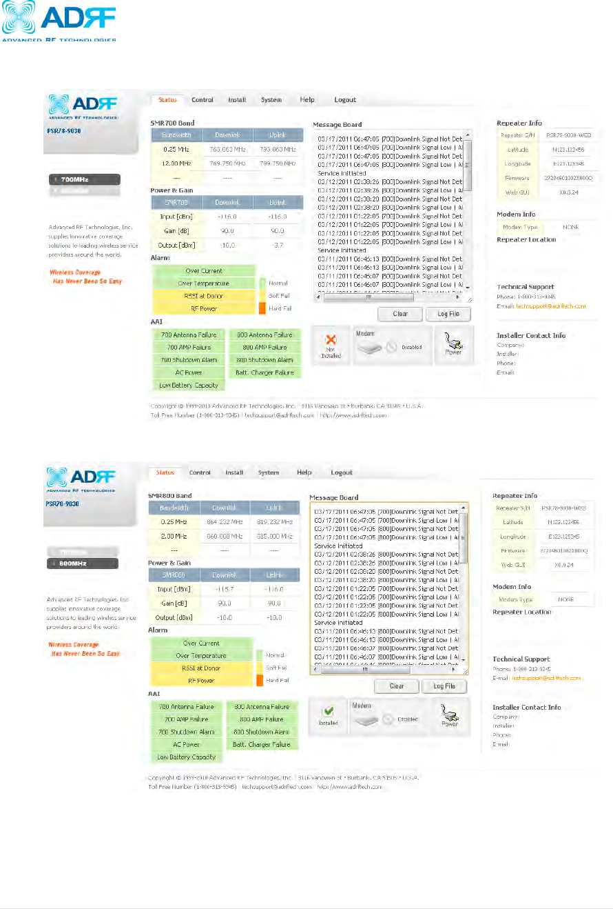
4.2 Status Tab
4.2.1 Status- 700 MHz
Status- 700 MHz
4.2.2 Status- 800 MHz
PSR78 Repeater
User Manual V0.1
Page | 6
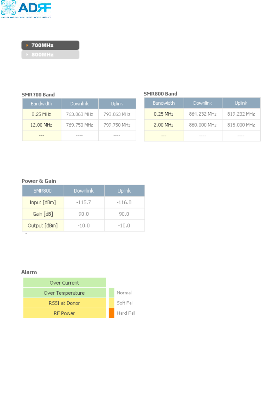
4.2.3 Side Navigation Bar
The side navigation bar located on the left hand side of the Web-GUI allows the user to switch between the two
technolgies supported by the system.
4.2.4 SMR700 Band / SMR800 Band
The band column displays the bandwidth that has been selected. The downlink column displays the center
frequency of the selected band. The uplink column displays the center frequency of the selected band.
4.2.5 Power & Gain
This section displays the Input, Gain, and Output for both downlink and uplink.
4.2.6 Alarm
This section displays the four (4) alarms statuses with three possible status conditions (Normal, Soft Fail or Hard
Fail).
PSR78 Repeater
User Manual V0.1
Page | 7
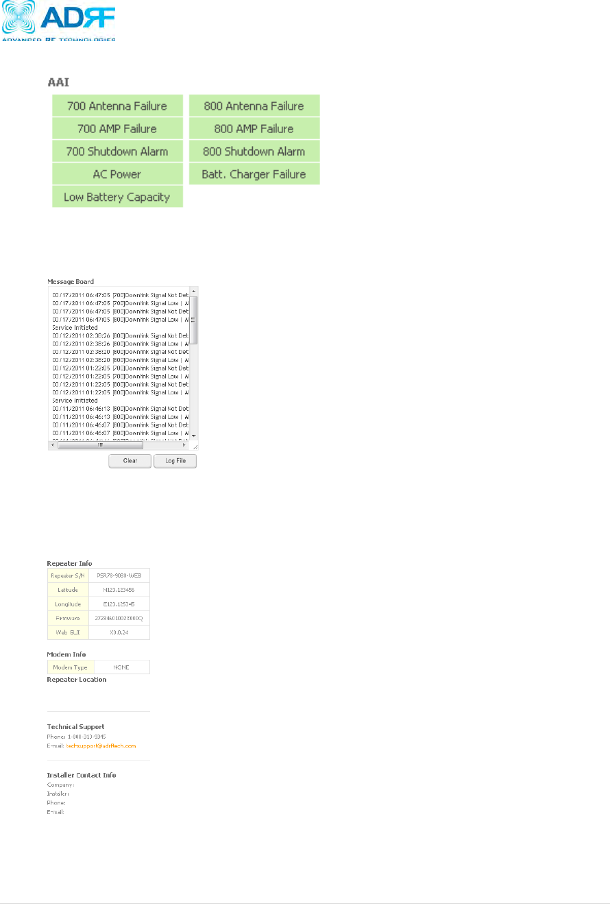
4.2.7 AAI
4.2.8 Message Board
Displays the recent system events for both the 700MHz and 800MHz sides.
o Clear: Clears the content that is currently being displayed on the Message Board
o Log File: Downloads the system Log File (events and alarms) to your computer
4.2.9 Repeater Info / Modem Info / Technical Support / Installer Contact Info
Repeater Info- Displays the serial number, latitude, longitude, and firmware version
of the repeater
Modem Info- If an internal modem is present, the modem information appears in
this section
Technical Support- Displays ADRF’s Technical Support contact information
Installer Contact Info- Displays the contact information of the installer
PSR78 Repeater
User Manual V0.1
Page | 8
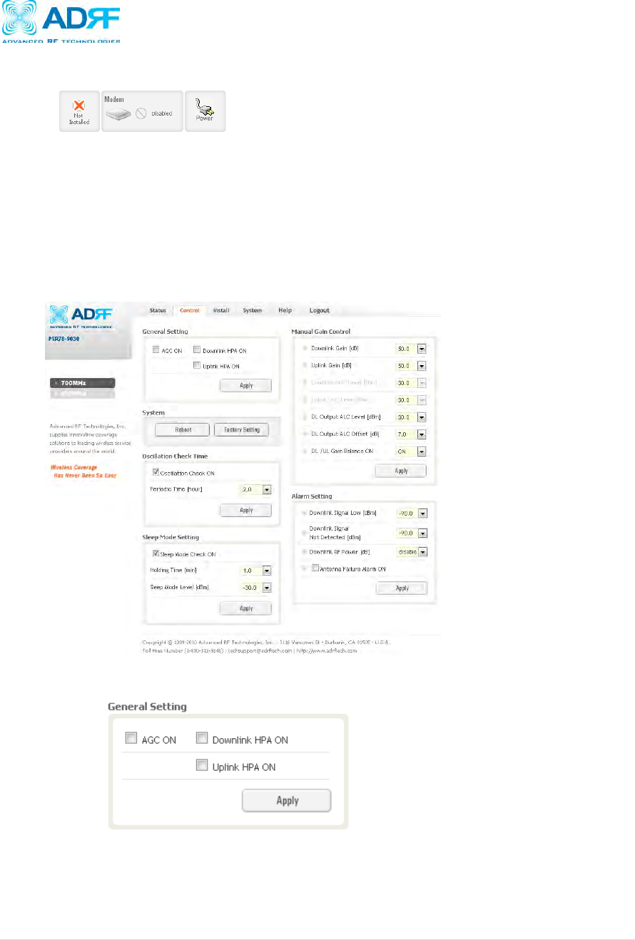
4.2.10 Install, Modem, and Power Status
o Installation: Displays whether or not the installation routine has been run (Not Installed or Installed)
o Modem: Displays the status of the modem
Disabled- No internal modem is present
Not Connected- Internal modem is detected, but no connection to the network has been
established
Connected- Internal modem is detected and a connection to the network has been established
o Power: Displays the power source that is currently being used
4.3 Control Tab
4.3.1 Control
Control- 700 MHz / 800 MHz
4.3.2 General Setting
o AGC ON: Enables or disables AGC (Automatic Gain Control)
o Downlink HPA ON: Enables or disables the DL HPA
o Uplink HPA ON: Enables or disabled the UL HPA
To enable any of the settings, click on the checkbox and click the Apply button.
PSR78 Repeater
User Manual V0.1
Page | 9
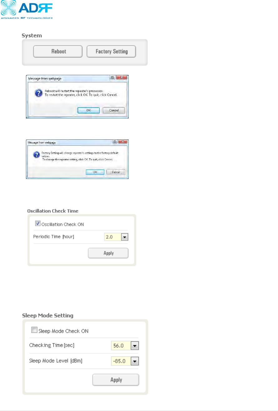
4.3.3 System
o Reboot: Clicking the reboot button will have the following popup show up:
Click OK to reboot the repeater or click Cancel to exit out
o Factory Setting: Resets the repeater to the original factory settings
4.3.4 Oscillation Check Time
This section allows the user to enable or disable the oscillation check feature and also specify the time interval at
which the repeater checks for oscillation.
4.3.5 Sleep Mode Setting
Sleep mode function is designed to power off the UL HPA when there is no UL traffic. To enable Sleep Mode,
click on the check box next to “Sleep Mode Check ON” and click on the Apply button. The user can specify the
Idle time and the Sleep Mode Level from this page. If the signal drops below the Sleep Mode Level for the
specified amount of Idle time, then the UL HPA will shut off.
PSR78 Repeater
User Manual V0.1
Page | 10
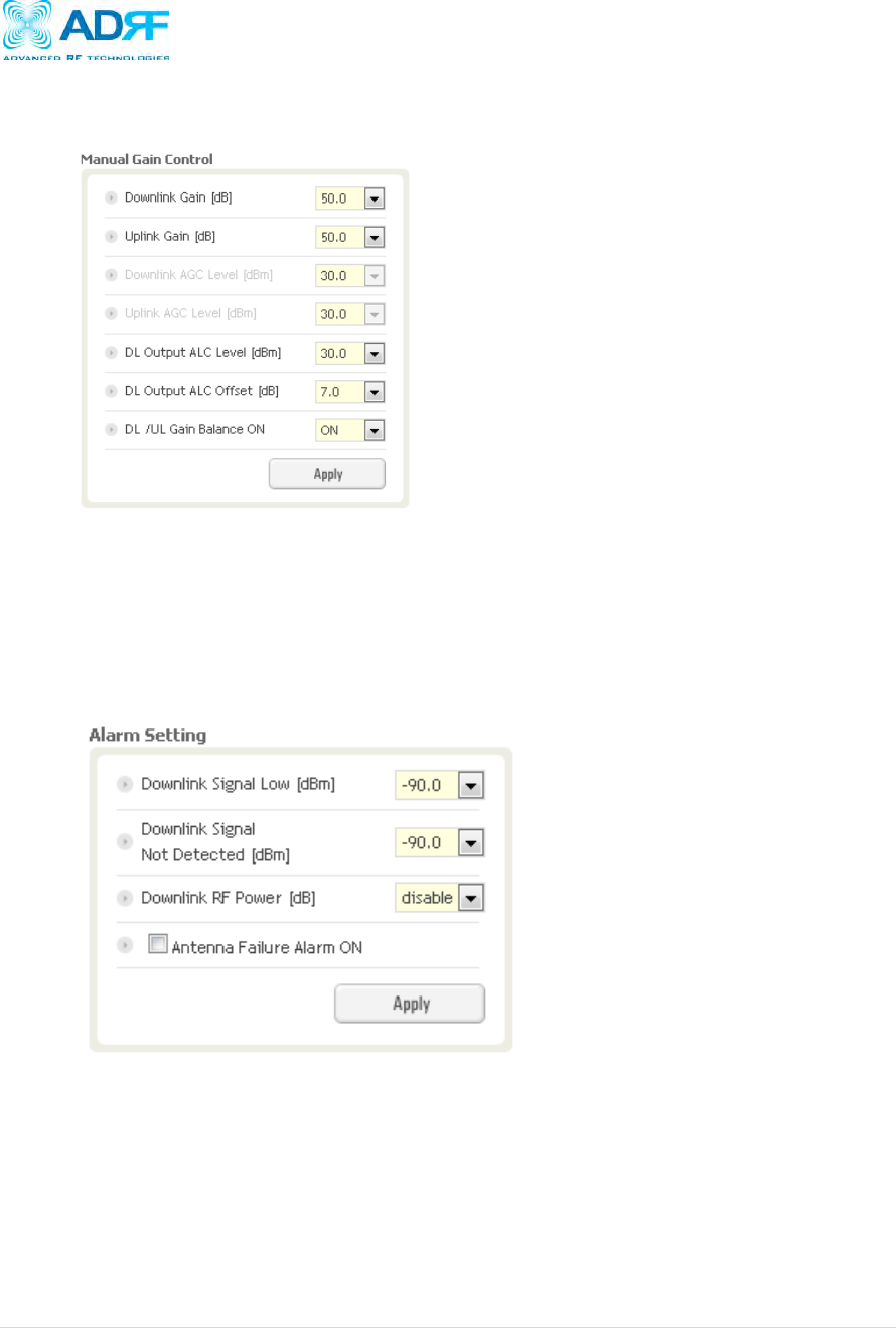
4.3.6 Manual Gain Control
o Downlink Gain: Allows the DL gain to be adjusted manually when AGC is OFF
o Uplink Gain: Allows the UL gain to be adjusted manually when AGC is OFF
o Downlink AGC Level: Allows the user to set the DL gain when AGC is enabled
o Uplink AGC Level: Allows the user to set the UL gain when AGC is enabled
o DL Output ALC Level:
o DL Output ALC Offset:
o DL /UL Gain Balance ON:
4.3.7 Alarm Setting
o Downlink RSSI: Allows the user to specify the how weak the signal can be before triggering a “RSSI
at Donor” soft-fail alarm
o Downlink RF Power: Allows the user to set a maximum deviation value for the downlink RF power
For example, if the input signal is -50 dBm and the gain is set to 60 dB, the expected output
power should be 10 dBm. If the Downlink RF Power alarm value is set to 6dB, then if the
output power is below 4 dBm, then this will trigger a soft-fail alarm
PSR78 Repeater
User Manual V0.1
Page | 11
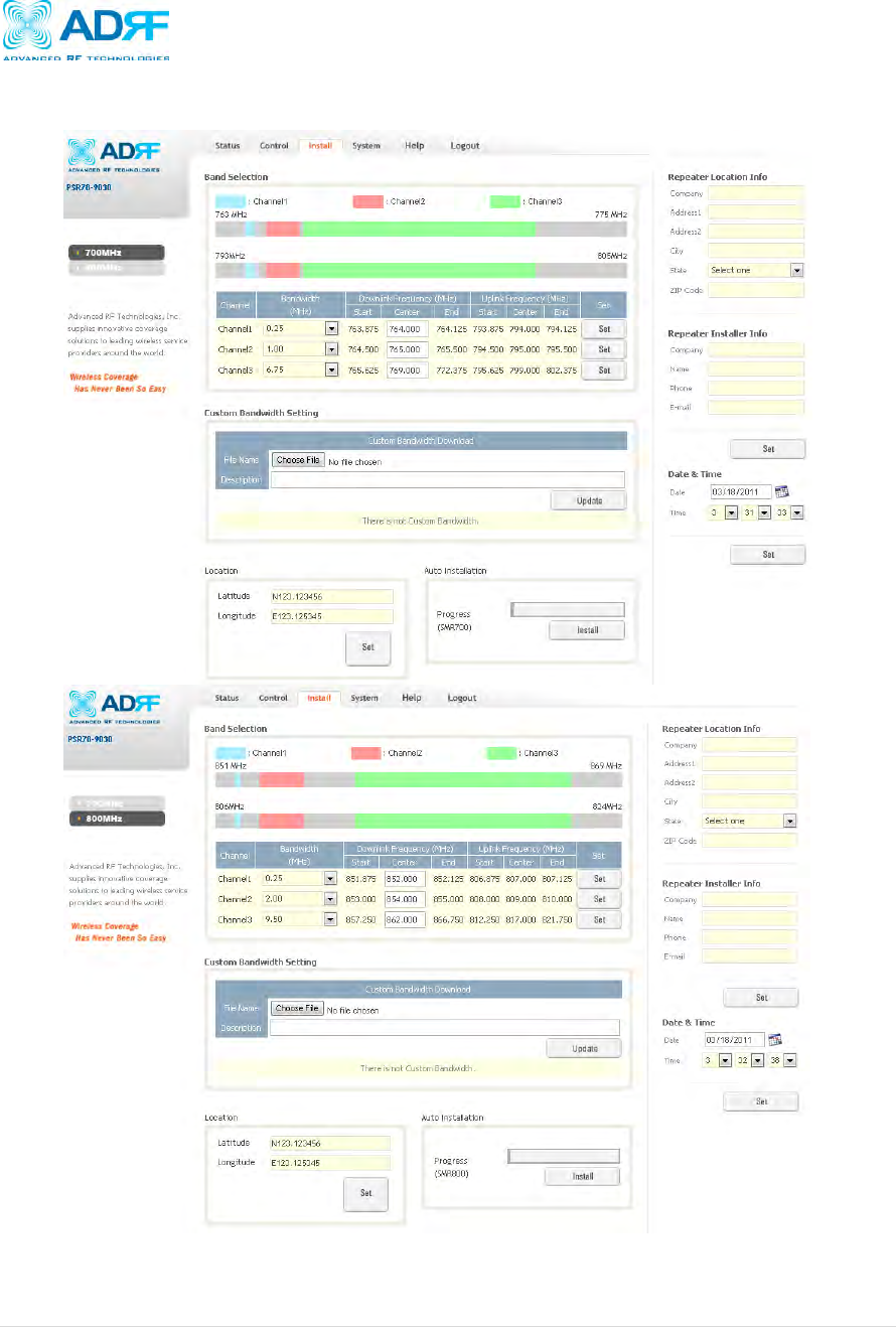
4.4 Install Tab
4.4.1 Install- 700MHz / 800 MHz
PSR78 Repeater
User Manual V0.1
Page | 12
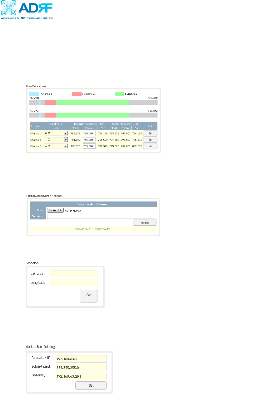
4.4.1.1 Bandwidth Selection
This section allows the user to specify the desired bandwidths and frequencies ranges to be amplified. First
select the desired bandwidth from the dropdown menu in the Bandwidth column. Next, input the center
frequencies of the desired frequencies and click the Set button. Once the Set button is pressed, desired
frequencies will be highlighted in the frequency table.
4.4.1.2 Custom Bandwidth Setting
This section allows the user to download custom filter bandwidth. The PSR78 supports bandwidths
selections in 250 KHz steps. If there are any special applications that require custom bandwidth, please
contact our Sales department.
4.4.1.3 Location
This section allows the user to input the latitude and the longitude of the repeater.
4.4.1.4 Modem Box Settings:
This section allows the user to specify an alternative Repeater IP, Subnet Mask, and Gateway settings.
These settings are enabled when the Host/Remote switch is set to the Remote position. When the
Host/Remote switch is changed, the repeater will reboot and will result in a temporary loss in coverage.
PSR78 Repeater
User Manual V0.1
Page | 13
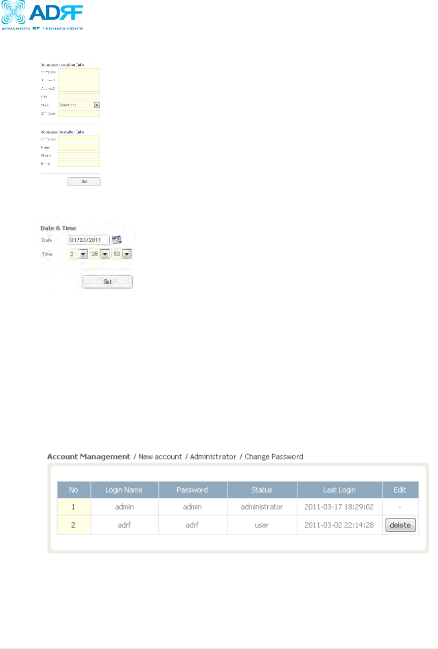
4.4.1.5 Repeater Location Info / Repeater Installer Info
This section allows the user to specify the address of the repeater and also the information of the installer.
4.4.1.5 Date & Time
This section allows the user to specify the current date and time.
4.5 System
The System tab allows the user to perform firmware updates, add/remove user accounts, and change the login
credentials of the Administrator.
4.5.1 System: Account
4.5.1.1 System: Account Management
The Account Management section will allow the Administrator to delete any user account. Please note that
the Account Management section is only available if you are logged into the system as the Administrator. To
delete a user account click on the Account Management link and under the Delete column, click on the delete
button.
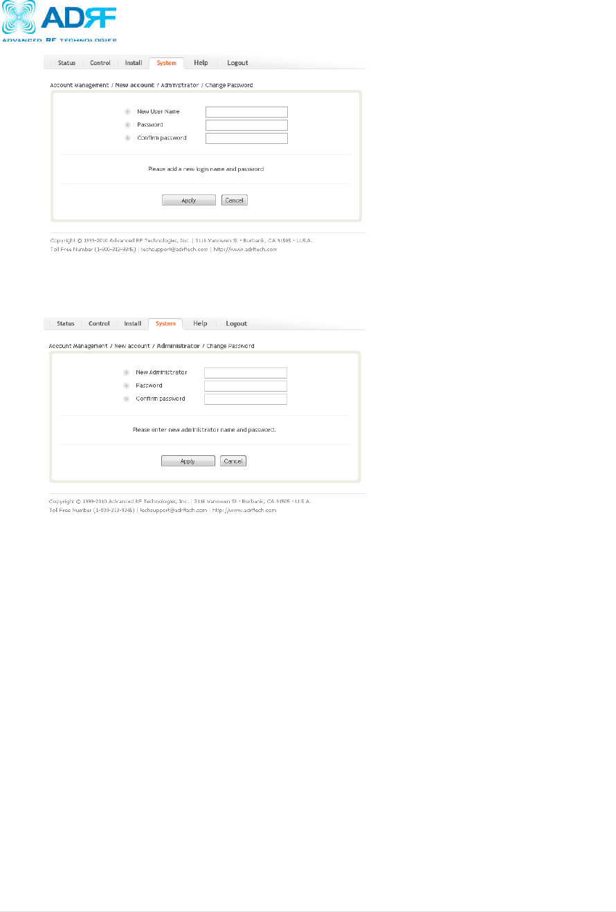
4.5.1.2 System: New Account
The New account section allows the Administrator to create a new user account. Please note that the New
account section is only available if you are logged into the system as the Administrator. To create a new user
account click on the New account link and fill in the fields highlighted in yellow as shown below.
PSR78 Repeater
User Manual V0.1
Page | 14
4.5.1.3 System: Administrator
The Administrator section allows the Administrator to create additional Administrator accounts. Please note
that the Administrator section is only available if you are logged into the system as the Administrator.
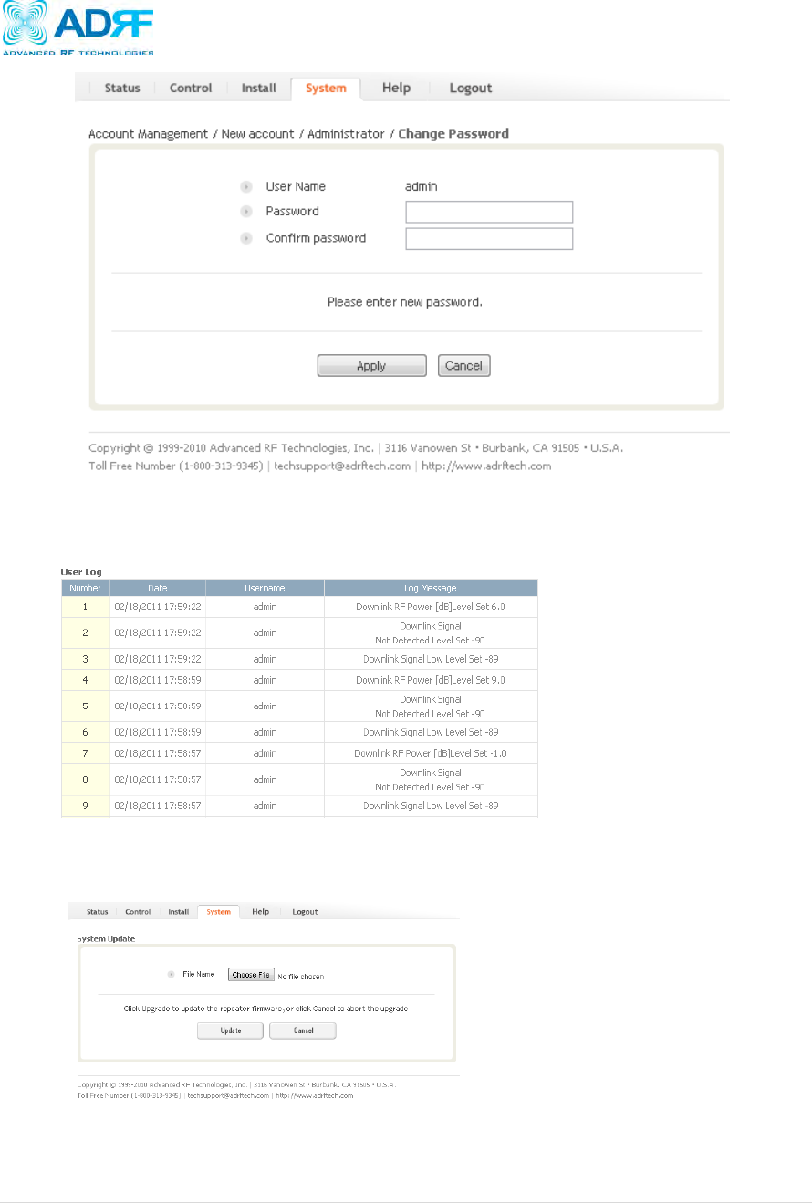
4.5.1.4 System: Change Password
The Change Password section allows the current user who is logged into the system to change their login
credentials.
PSR78 Repeater
User Manual V0.1
Page | 15
4.5.2 System: User Log
This section displays all the system activities that have taken place in the repeater along with the account
associated with that event.
4.5.3 System: Update
To perform a firmware update, click on the System tab and the following screen will show up.
Click on the Choose File… button and locate the firmware file
Click on the Upload button to perform the firmware update
Once the firmware update is complete, the following popup message will appear:

PSR78 Repeater
User Manual V0.1
Page | 16
4.6 Help
If an internet connection is available, clicking on the Help Tab will redirect the user to our Technical Support page.
4.7 Logout
Clicking the Logout button will log the current user off the system.

PSR78 Repeater
User Manual V0.1
Page | 17
5. Maintenance Guide for PSR78 Repeater
5.1 Periodic Inspection Checklist
a) Check for loose connections between the repeater and antennas. If connections are loose, make sure that all
connections are tightly fastened properly.
b) Cables and connectors are in good condition.
c) Ensure that the repeater brackets are in good. condition and that the repeater is securely fastened
5.2 Preventive Measures for Optimal Operation
5.2.1 Recommendations
Perform the Periodic Inspection Checklist quarterly or semi-annually.
5.2.2 Precautions
Do not operate the repeater with the antennas in extremely close proximity to one another as this may
cause damage to the repeater.
Do not change the parameters unless instructed to do so by an authorized supervisor.
Do not move the repeater unless instructed to do so by an authorized supervisor.
Do not detach any cables to the repeater unless repair of respective components is necessary.

PSR78 Repeater
User Manual V0.1
Page | 18
6. Warranty and Repair Policy
6.1 General Warranty
The PSR78 carries a Standard Warranty period of two (2) years unless indicated otherwise on the package or in the
acknowledgment of the purchase order.
6.2 Limitations of Warranty
Your exclusive remedy for any defective product is limited to the repair or replacement of the defective product. Advanced
RF Technologies, Inc. may elect which remedy or combination of remedies to provide in its sole discretion. Advanced
RF Technologies, Inc. shall have a reasonable time after determining that a defective product exists to repair or replace
the problem unit. Advanced RF Technologies, Inc. warranty applies to repaired or replaced products for the balance of the
applicable period of the original warranty or ninety days from the date of shipment of a repaired or replaced product,
whichever is longer.
6.3 Limitation of Damages
The liability for any defective product shall in no event exceed the purchase price for the defective product.
6.4 No Consequential Damages
Advanced RF Technologies, Inc. has no liability for general, consequential, incidental or special damages.
6.5 Additional Limitation on Warranty
Advanced RF Technologies, Inc. standard warranty does not cover products which have been received improperly
packaged, altered, or physically damaged. For example, broken warranty seal, labels exhibiting tampering, physically
abused enclosure, broken pins on connectors, any modifications made without Advanced RF Technologies, Inc.
authorization, will void all warranty.
6.6 Return Material Authorization (RMA)
No product may be returned directly to Advanced RF Technologies, Inc. without first getting an approval from Advanced
RF Technologies, Inc. If it is determined that the product may be defective, you will be given an RMA number and
instructions in how to return the product. An unauthorized return, i.e., one for which an RMA number has not been issued,
will be returned to you at your expense. Authorized returns are to be shipped to the address on the RMA in an approved
shipping container. You will be given our courier information. It is suggested that the original box and packaging materials
should be kept if an occasion arises where a defective product needs to be shipped back to Advanced RF Technologies,
Inc. To request an RMA, please call (800) 313-9345 or send an email to techsupport@adrftech.com.
PSR78 Repeater
User Manual V0.1
Page | 19
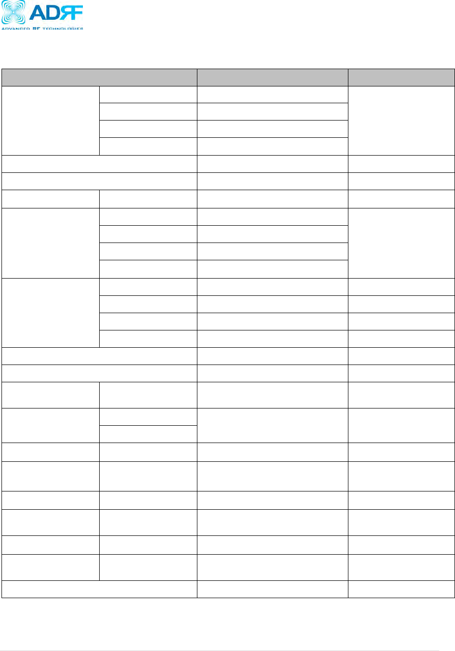
7. Specifications
7.1 Electrical Specifications
Parameters
Specifications
Remark
Frequency
SMR700 UL
793 ~ 805MHz (BW: 12MHz)
SMR700 DL
763 ~ 775 MHz (BW: 12MHz)
SMR800 DL
851 ~ 869 MHz (BW: 18MHz)
SMR800 UL
806 ~ 824 MHz (BW: 18MHz)
Port
2Donor, 2Server
Composite Output Power
+36 dBm
700 + 800 MHz
Gain Ripple
DL / UL
≤±1.5 dB p-p
700 + 800 MHz
Gain
(DL / UL)
Maximum
90 dB
Range
30 dB
Step
0.5 dB
Tolerance
≤1 dB
Input
SMR700 UL
-60 ~ -30dBm
SMR700 DL
-60 ~ -30dBm
SMR800 DL
-60 ~ -30dBm
SMR800 UL
-60 ~ -30dBm
Channel Type
Public Safety Multiple Channel
Modulation Type
iDEN
Roll Offs
DL / UL
≥65 dBc
@ 0.5 MHz outside
pass band
Adjustable
Band Edge
SMR700 DL/UL
Resolution: 250kHz
(Filter Download function.)
250 kHz steps Size.
SMR800 DL/UL
OIP3
DL / UL
≥ 50 dB
@ Gain 90 dB/60 dB
IMD
DL / UL
≥ 40 dBc @ +30dBm total.
Max Output Power @ 2Tone/1MHz
At least FCC Rule
(-13dBm)
VSWR
DL / UL
≤ 1.5: 1
RF Spurious
Emission
DL / UL
≤ -13 dBm
Noise Figure
UL
≤ 5 dB @max gain
( UL-Only)
Delay
DL / UL
≤ 8 us@ Standard Product.
Special Request It will
be increase.
Impedance
50 Ohms
PSR78 Repeater
User Manual V0.1
Page | 20
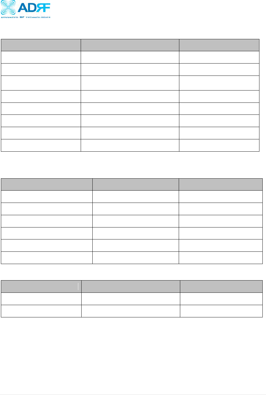
7.2 Mechanical Specifications
Parameters
Specifications
Remark
Dimension
17.9 X 22.5 X 12.3 inches
Mount bracket excluded
Weight
< 92 lbs
Mount bracket excluded
RF Ports
N-type (F)
Donor & Server Antenna
Ports
Local Interface
RJ45 (DHCP)
Cooling
12V FAN
2EA
IP Class
NEMA 4
Outdoor Type
Mounting Type
Wall Mounting
Color
Red
7.3 Power Specifications
Parameters
Specifications
Comments
AC Power
120 AC
AC Frequency
45 ~ 65 Hz
AC Supply Protection
Fuse
DC Power Option
-40 ~ -60 V / +20 ~ 30 V
Power Consumption
≤ 250 W
Ground
External Threaded Stud
7.4 Environment Specifications
Parameters
Specifications
Remark
Operating Temperature
-10 ~ +50 Cº
Ambient
Relative Humidity
5 ~ 95 %, non-condensing

PSR78 Repeater
User Manual V0.1
Page | 21
7.5 Alarm Specification
No
Parameters
Specifications
Display
1
Synthesizer Lock
PLL Fail
Web GUI
2
RF Power Alarm
Internal Amp Fail
Web GUI
3
DSP Fail
DSP Alarm
Web GUI
4
700 Antenna Malfunction
VSWR Alarm
Web GUI
Dry Contact
5
800 Antenna Malfunction
VSWR Alarm
Web GUI
Dry Contact
6
700 Signal Booster Failure
Synthesizer
Lock, DSP Fail.
Web GUI
Dry Contact
7
800 Signal Booster Failure
Synthesizer
Lock, DSP Fail.
Web GUI
Dry Contact
8
700 Shut Down alarm
Hard Fail Alarm
Web GUI
Dry Contact
9
800 Shut Down alarm
Hard Fail Alarm
Web GUI
Dry Contact
10
Power Supply supervisory
Alarm
Loss of normal
AC Power
Web GUI
Dry Contact
11
Failure of battery
charger.
Web GUI
Dry Contact
12
Low Battery
Capacity
Web GUI
Dry Contact
PSR78 Repeater
User Manual V0.1
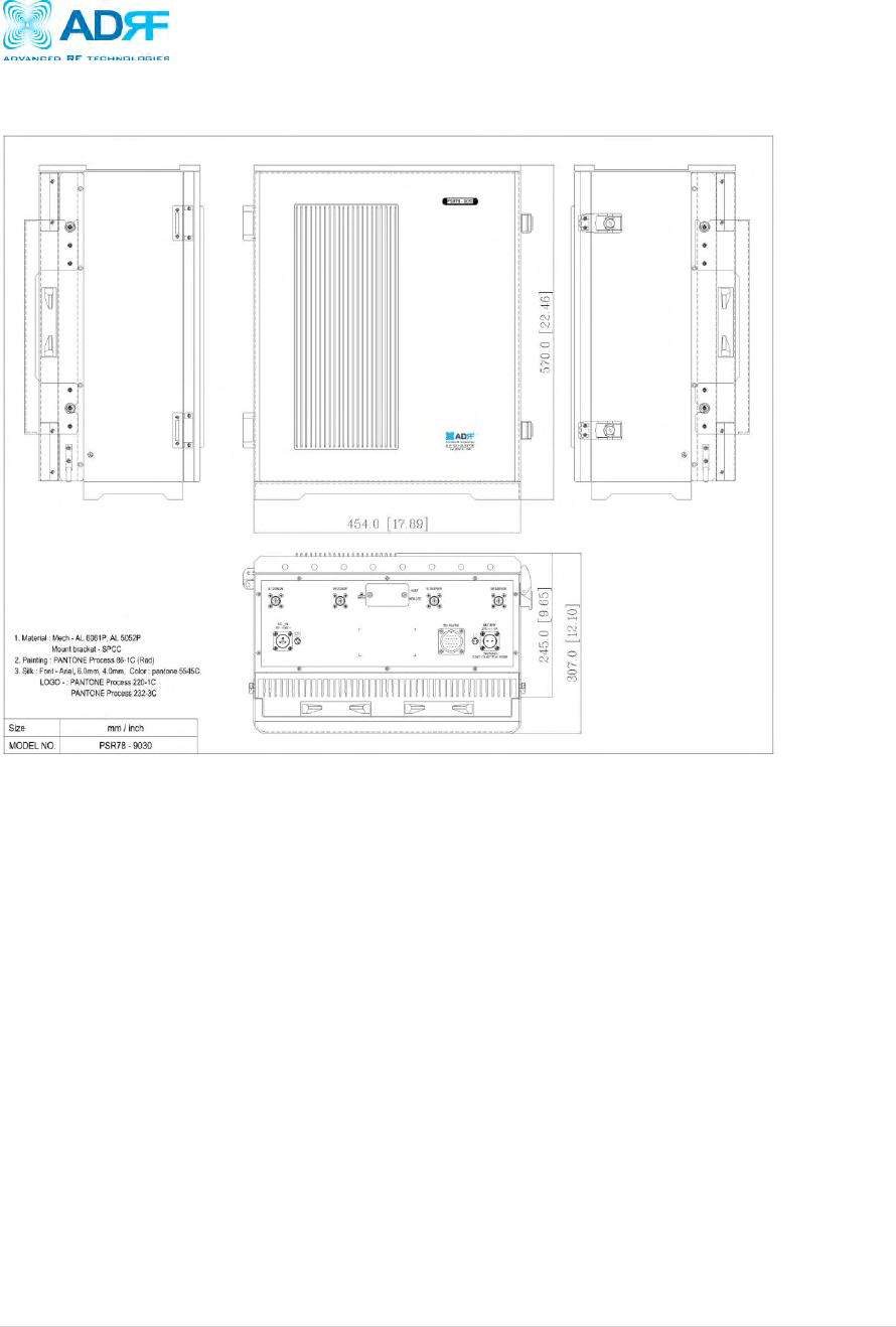
Page | 22
Appendix A: Mechanical Drawing
Figure 7: PSR78 mechanical drawing

PSR78 Repeater
User Manual V0.1
Page | 23
Appendix B: Shutdown Retry Logic
The function of the built-in shutdown routine is to protect the repeater from any further damage from a hard-fail that the
system may be experiencing.
Within 5 seconds of a hard-fail alarm being detected, the repeater will start the shutdown routine. The repeater will shut
down by powering of the HPAs (high-powered amplifiers) for 30 seconds.
After 30 seconds have elapsed, the repeater will power on the HPAs and check to see if the hard-fail alarm still exist. If
the hard-fail alarm still exists, then the repeater will shut down for 1 minute (double the time of the previous shutdown
time).
After 1 minute has elapsed, the repeater will power on the HPAs and check to see if the hard-fail alarm still exist. If the
hard-fail alarm still exists, then the repeater will shut down for 2 minutes (double the time of the previous shutdown time).
The shutdown routine will repeat itself a total of 10 times. If the hard-fail alarm still exists after the 10th retry, then the
repeater will turn on its HPAs permanently until a reset is performed.