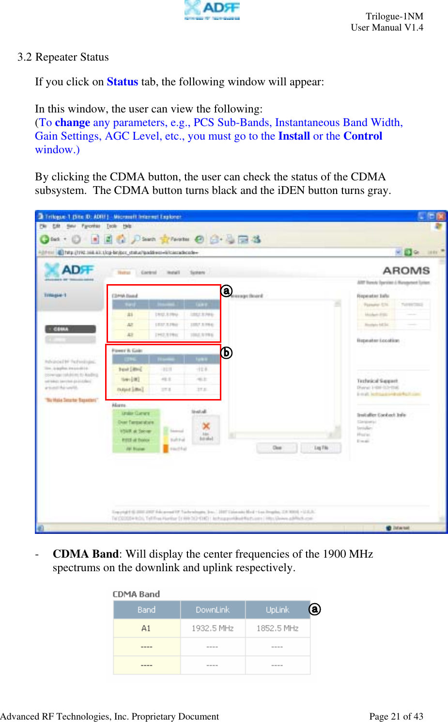
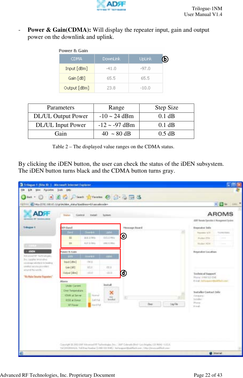
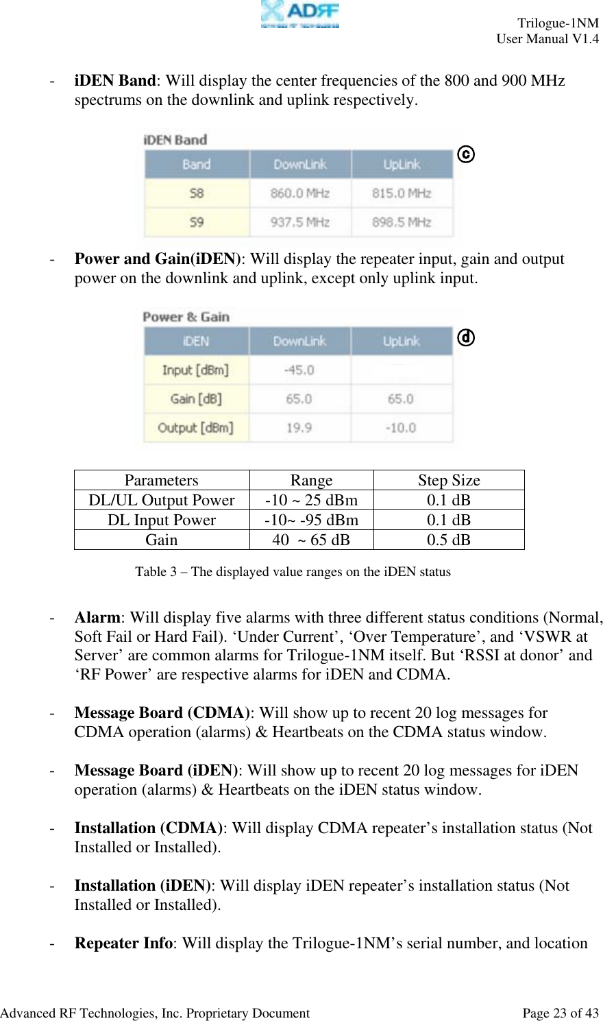
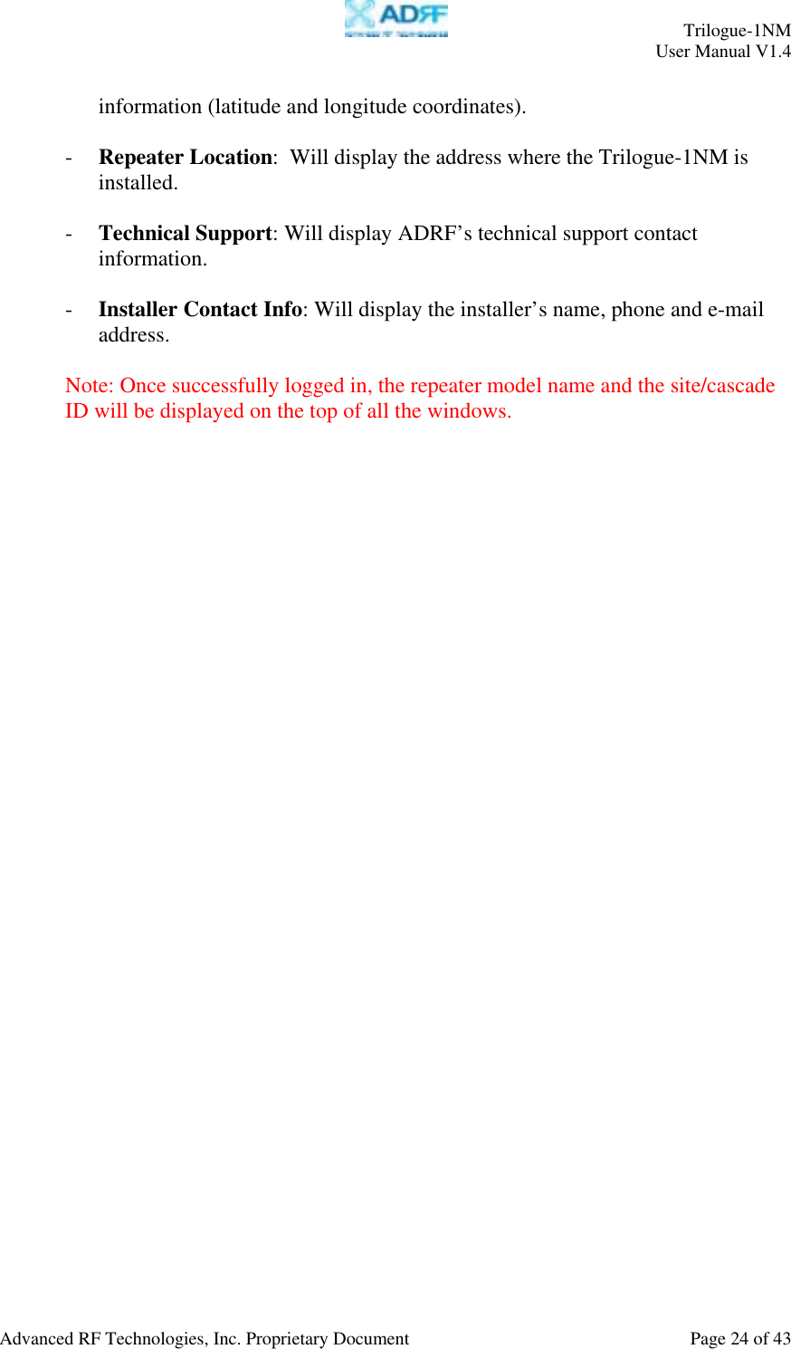
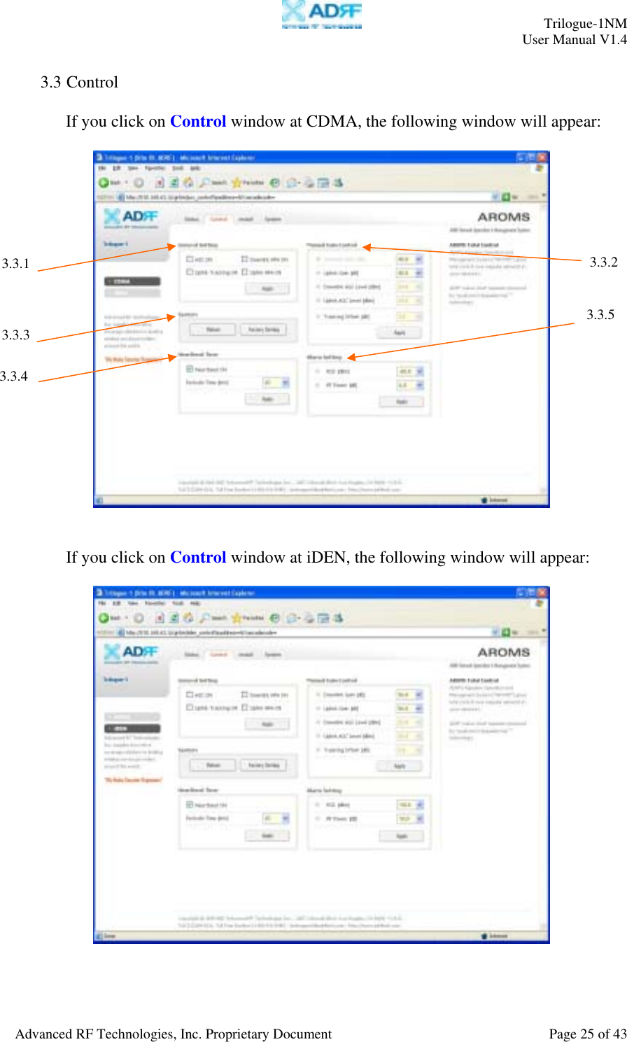
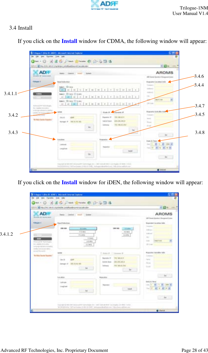
Advanced RF Technologies TRILOGUE1 Trilogue-1NM repeater with digital filtering User Manual Manual
Advanced RF Technologies, Inc. Trilogue-1NM repeater with digital filtering Manual
UserManual.wiki
>
Advanced RF Technologies
>
TRILOGUE1 User Manual
Manual
Navigation menu
Upload a User Manual
Namespaces
Wiki Guide
HTML
PDF
Info
Views
User Manual
Discussion / Help
Navigation
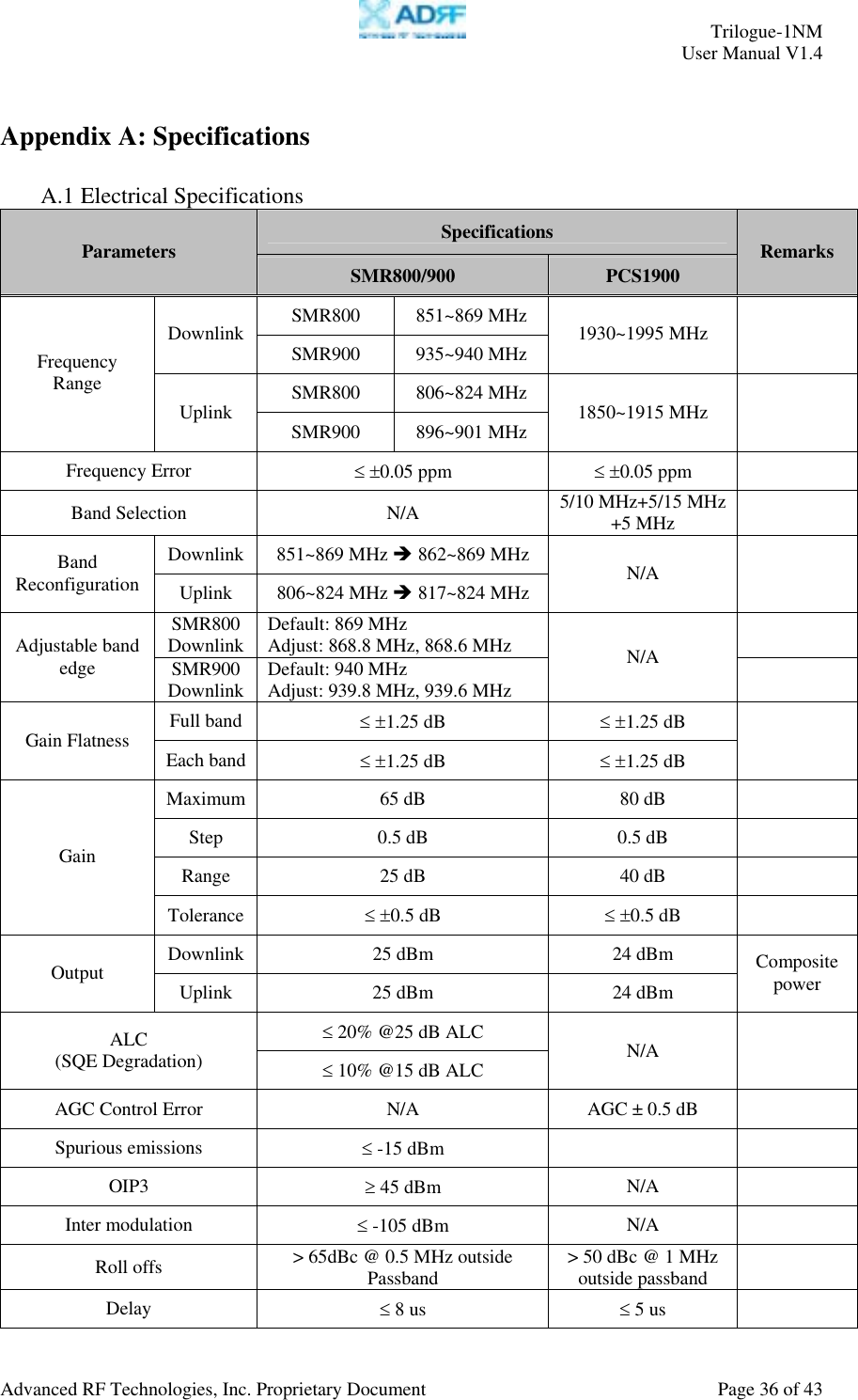
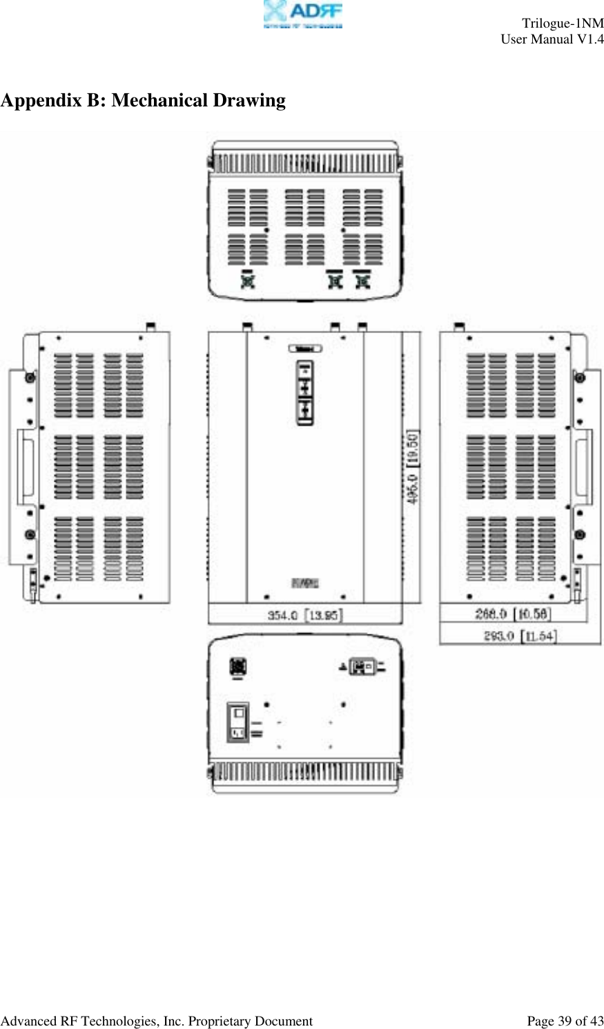
![Trilogue-1NM User Manual V1.4 Advanced RF Technologies, Inc. Proprietary Document Page 5 of 43 5.1 General Warranty................................................................................................. 35 5.2 Limitations of Warranty....................................................................................... 35 5.3 Limitation of Damages......................................................................................... 35 5.4 No Consequential Damages ................................................................................. 35 5.5 Additional Limitation on Warranty...................................................................... 35 5.6 Return Material Authorization (RMA) ................................................................ 35 APPENDIX A: SPECIFICATIONS.............................................................................. 36 A.1 Electrical Specifications...................................................................................... 36 A.2 Mechanical Specifications................................................................................... 37 A.3 Environmental Specifications.............................................................................. 37 A.4 Power Specifications........................................................................................... 38 A.5 Other Specifications............................................................................................ 38 APPENDIX B: MECHANICAL DRAWING .............................................................. 39 APPENDIX C: TRILOGUE-1NM OVERVIEW ........................................................ 40 C.1 Block Diagram..................................................................................................... 40 - 1 Layer [iDEN] -.............................................................................................. 40 - 2 Layer [CDMA] -........................................................................................... 40 C.2 Components......................................................................................................... 41 - 1 Layer [iDEN] -.............................................................................................. 41 - 2 Layer [CDMA] -........................................................................................... 42](https://usermanual.wiki/Advanced-RF-Technologies/TRILOGUE1/User-Guide-925747-Page-5.png)
![Trilogue-1NM User Manual V1.4 Advanced RF Technologies, Inc. Proprietary Document Page 40 of 43 Appendix C: Trilogue-1NM Overview C.1 Block Diagram - 1 Layer [iDEN] - - 2 Layer [CDMA] -](https://usermanual.wiki/Advanced-RF-Technologies/TRILOGUE1/User-Guide-925747-Page-40.png)
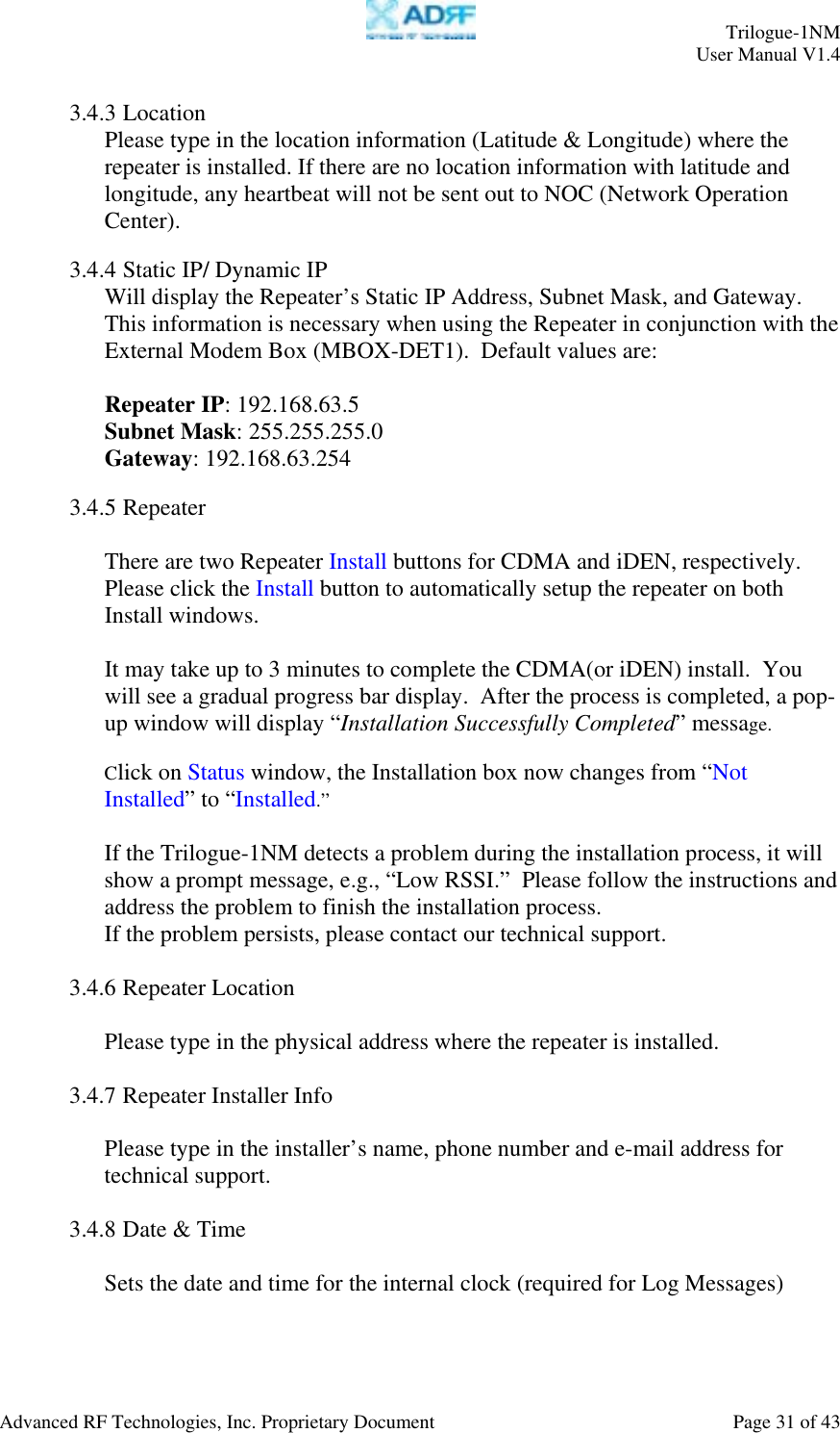
![Trilogue-1NM User Manual V1.4 Advanced RF Technologies, Inc. Proprietary Document Page 41 of 43 C.2 Components - 1 Layer [iDEN] - Quad plexerPower Supply UP/Down ConverterDigital Filter Noise Filter Controller](https://usermanual.wiki/Advanced-RF-Technologies/TRILOGUE1/User-Guide-925747-Page-41.png)
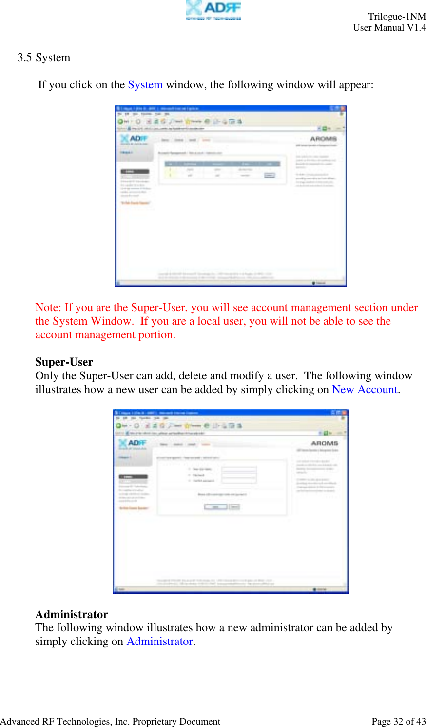
![Trilogue-1NM User Manual V1.4 Advanced RF Technologies, Inc. Proprietary Document Page 42 of 43 - 2 Layer [CDMA] - Power port for modem box CDMA DuplexerCombiner Controller Server Port iDEN Donor Port CDMA Donor Port DHCP Sub BoardUP/Down Converter Downlink UDC Uplink UDC Adapter for modem box](https://usermanual.wiki/Advanced-RF-Technologies/TRILOGUE1/User-Guide-925747-Page-42.png)