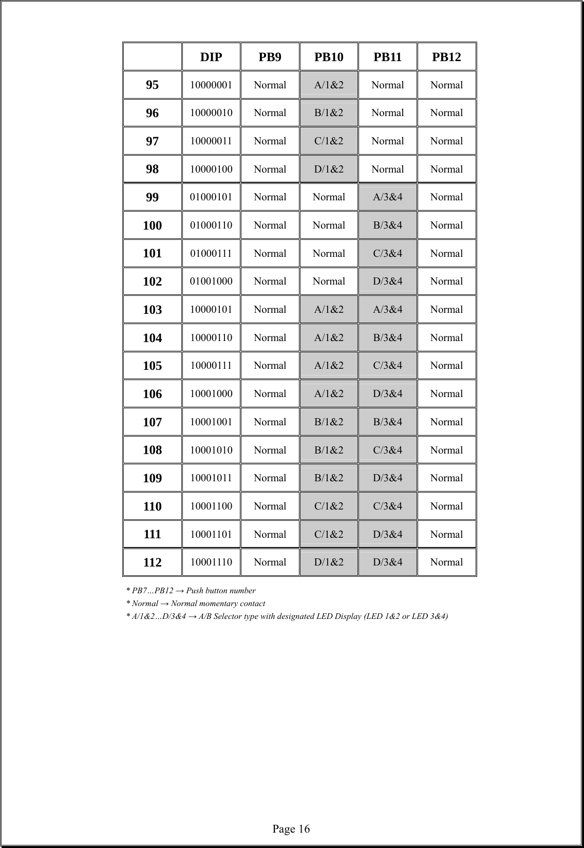
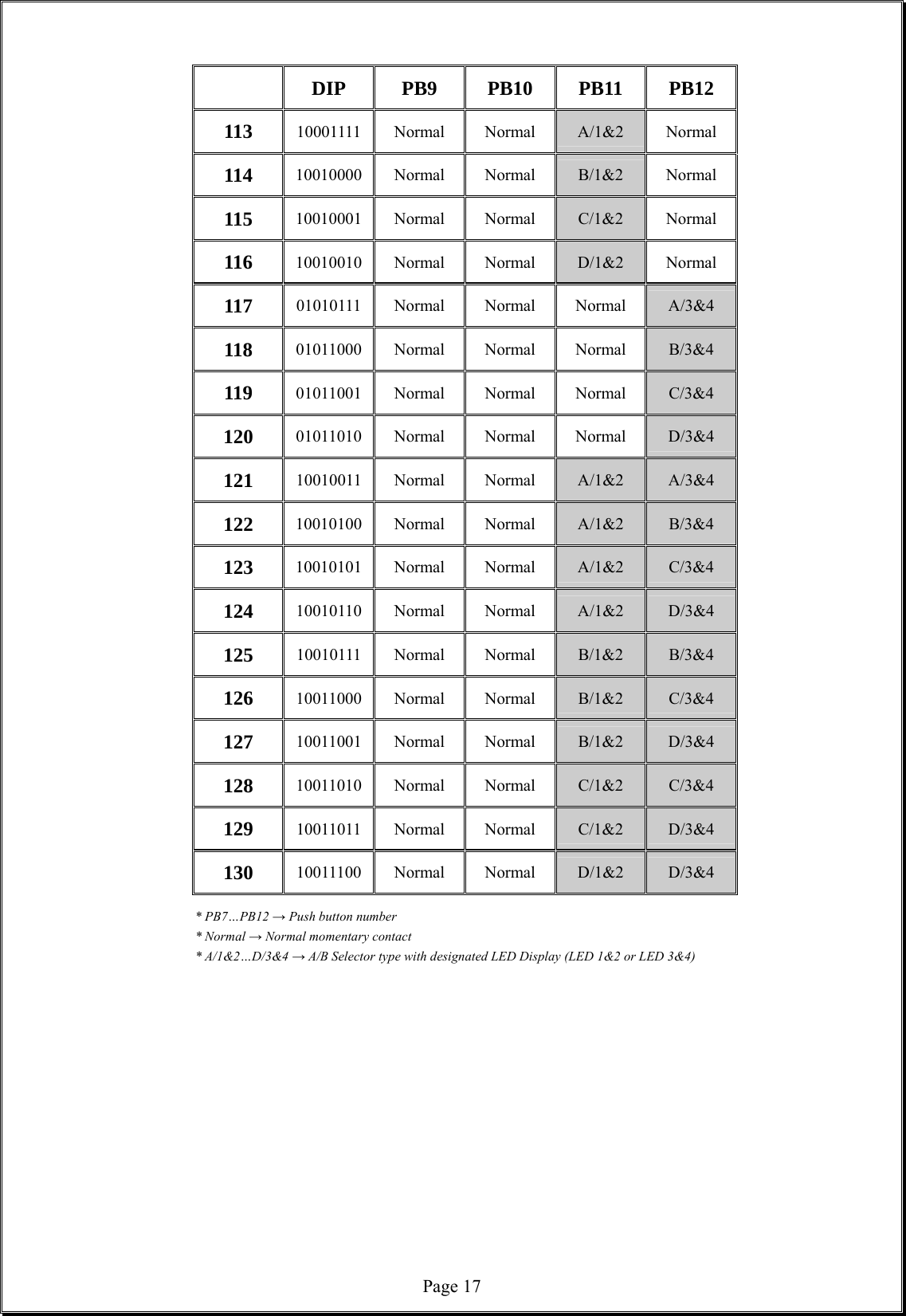
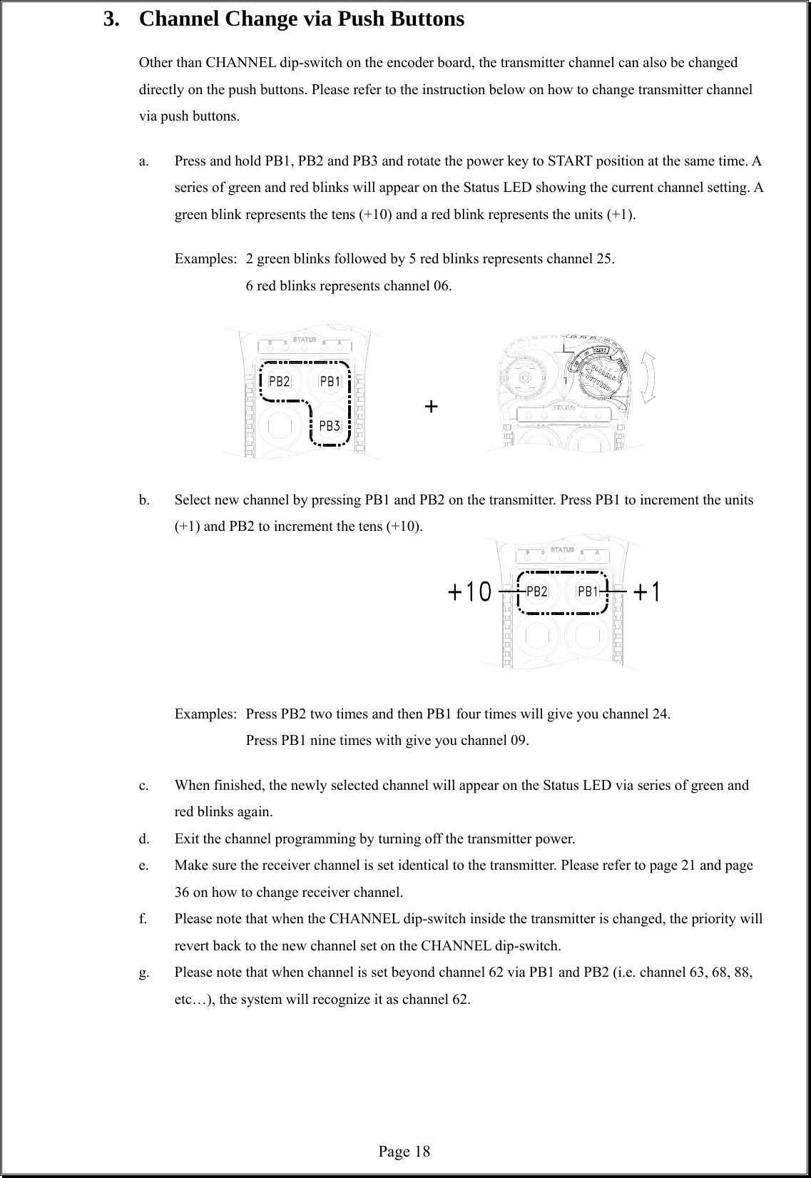
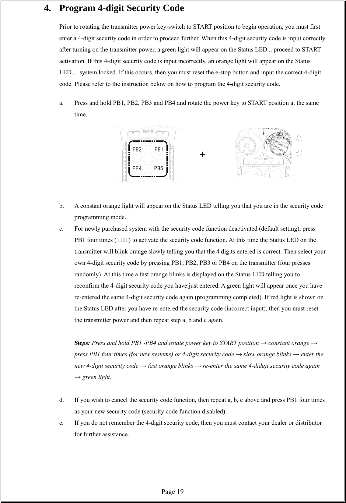
Advanced Radiotech ARCFLEXEX Industrial radio remote control systems User Manual Flex EX User s Manual
Advanced Radiotech Corporation Industrial radio remote control systems Flex EX User s Manual
UserManual.wiki
>
Advanced Radiotech
>
ARCFLEXEX User Manual
User manual
Navigation menu
Upload a User Manual
Namespaces
Wiki Guide
HTML
PDF
Info
Views
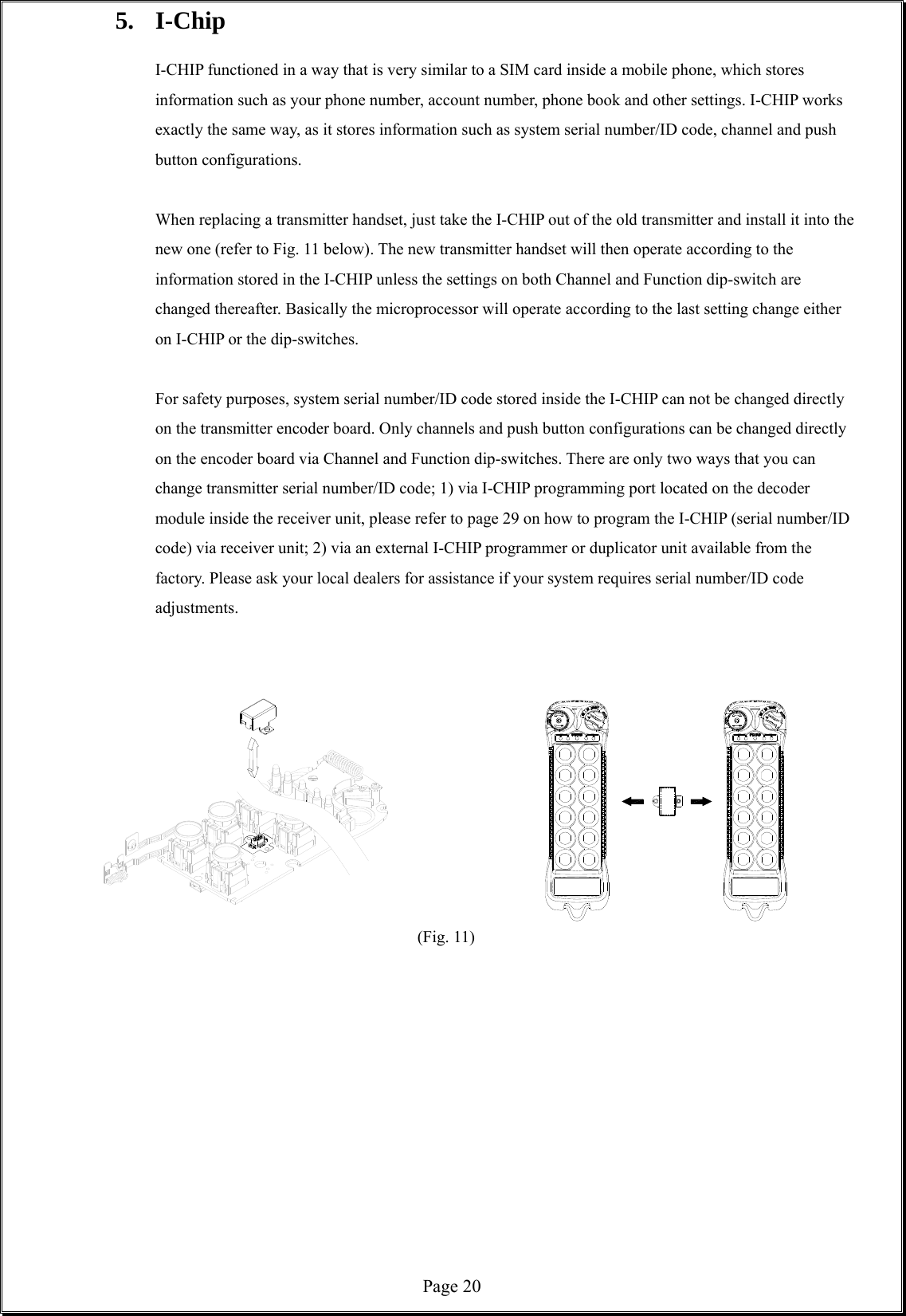
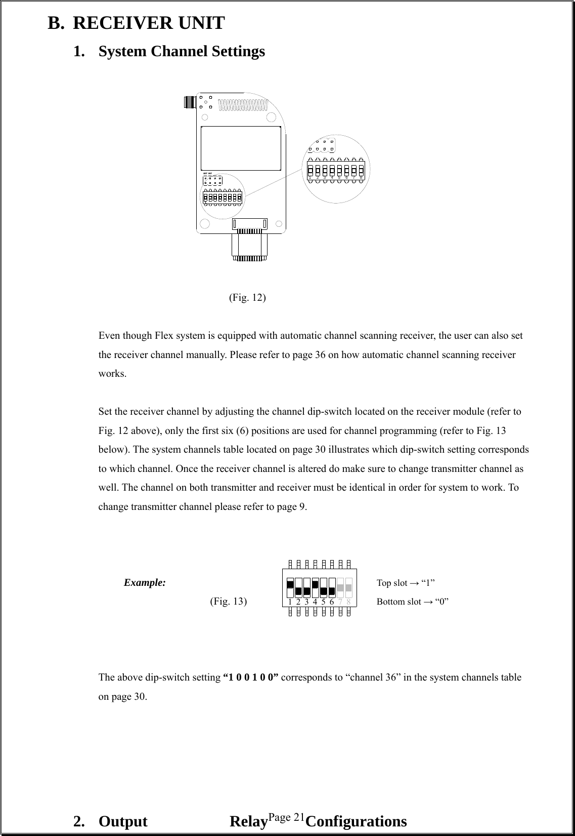
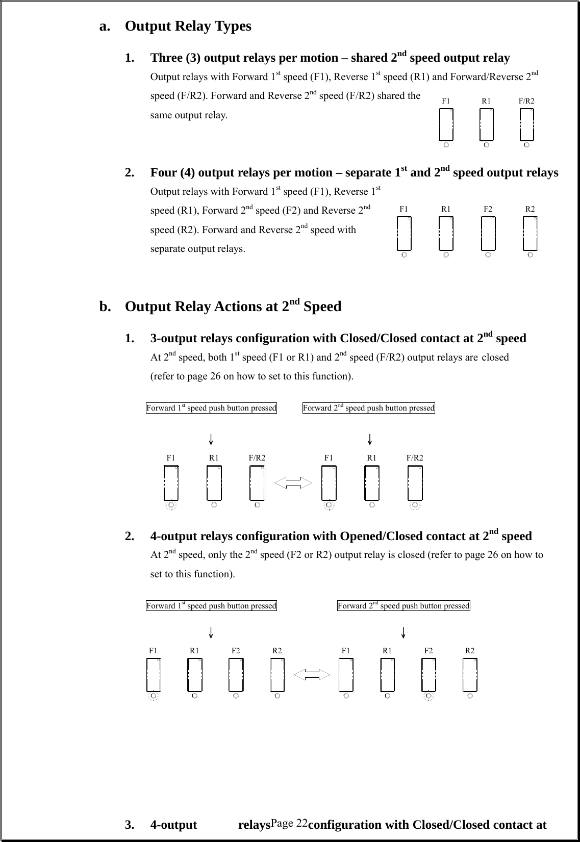
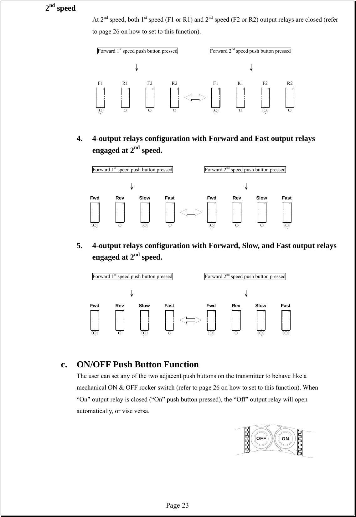
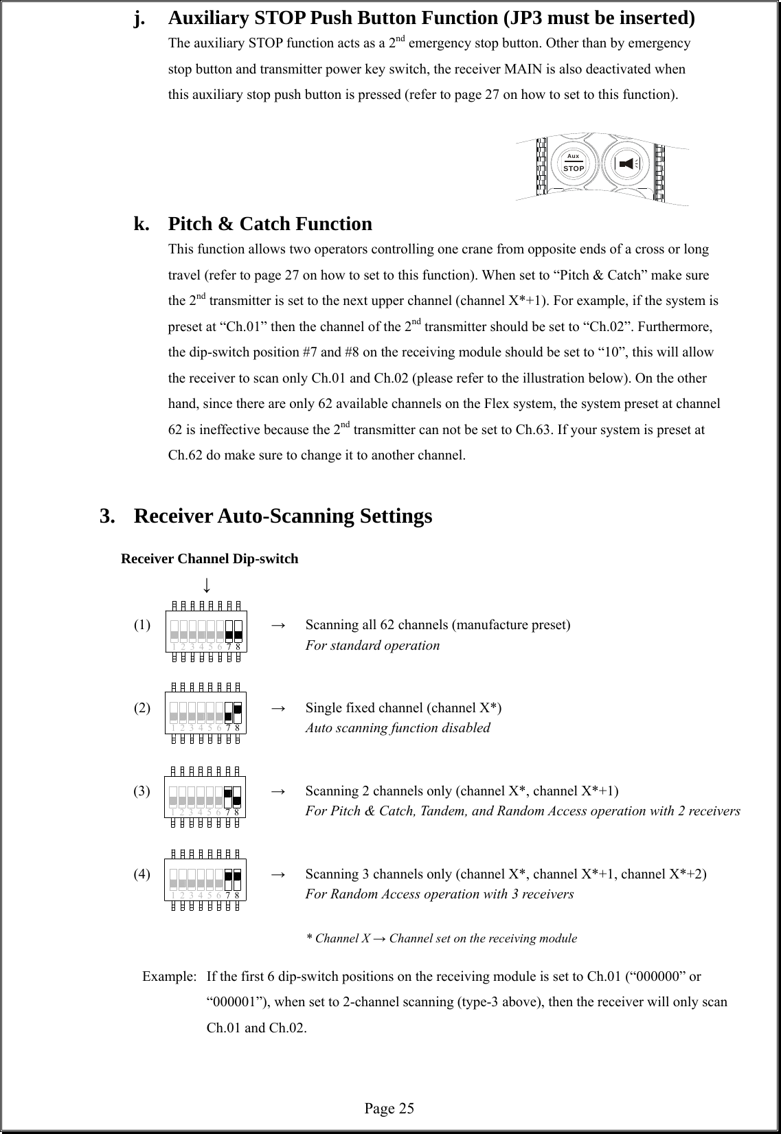
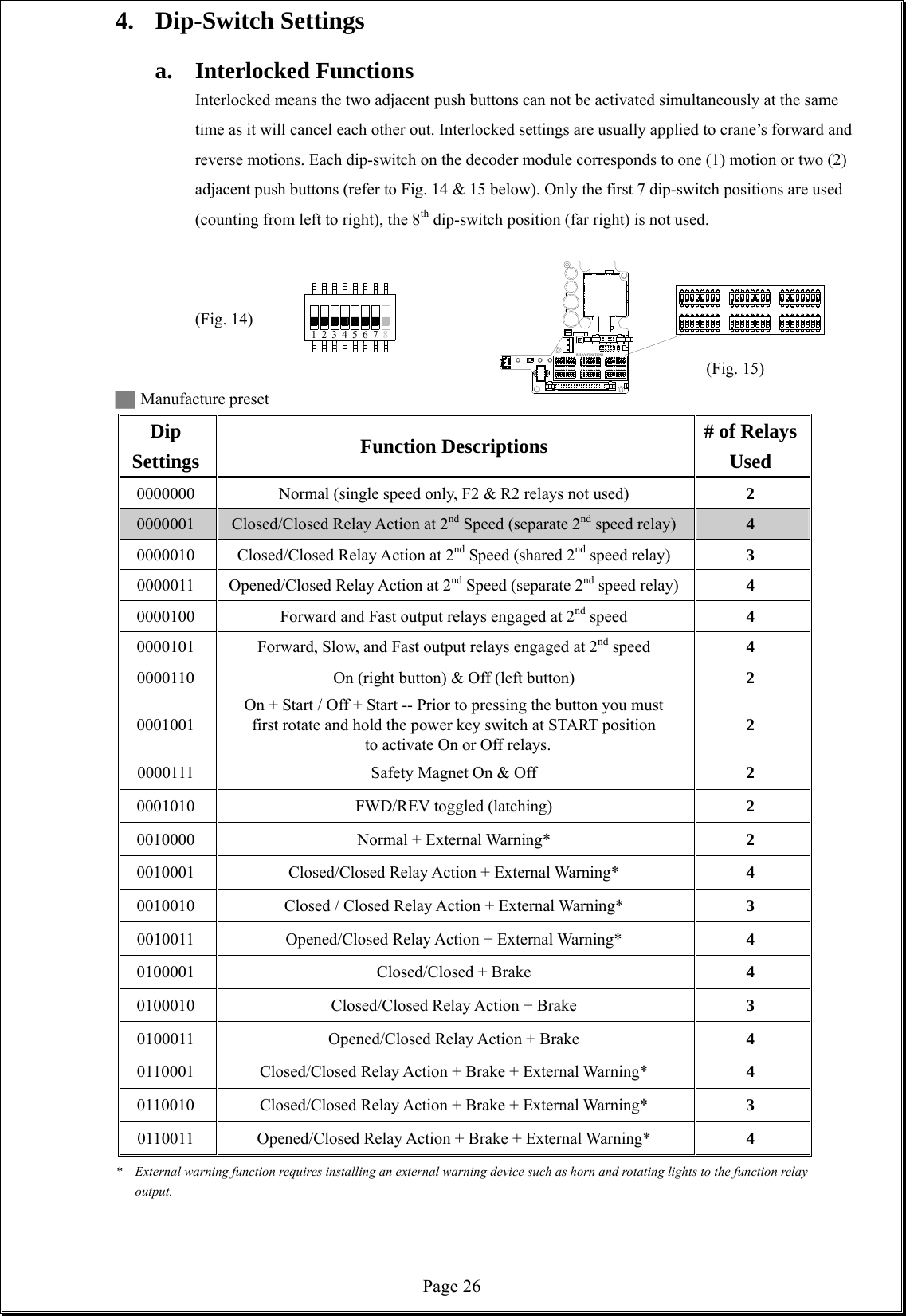
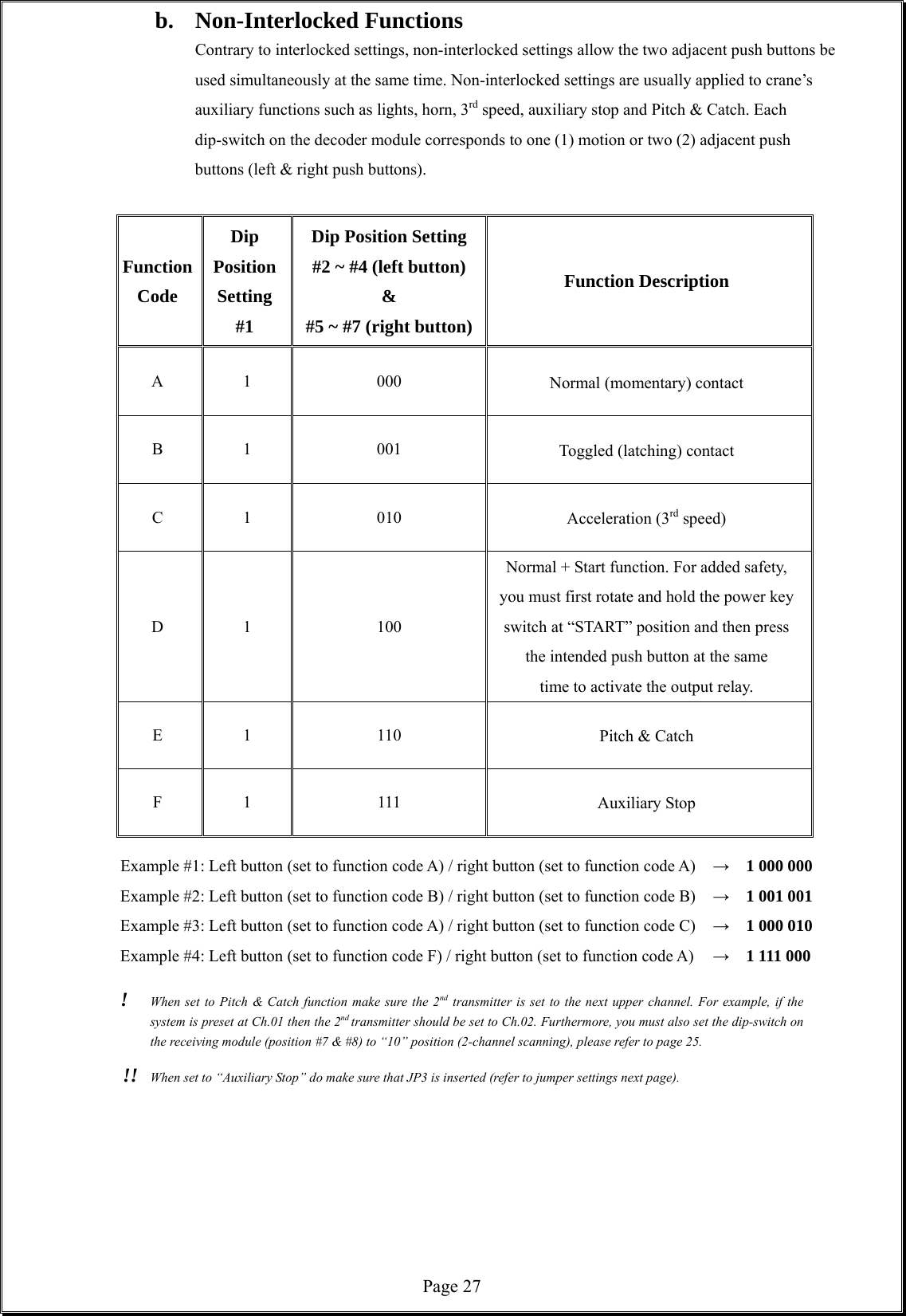
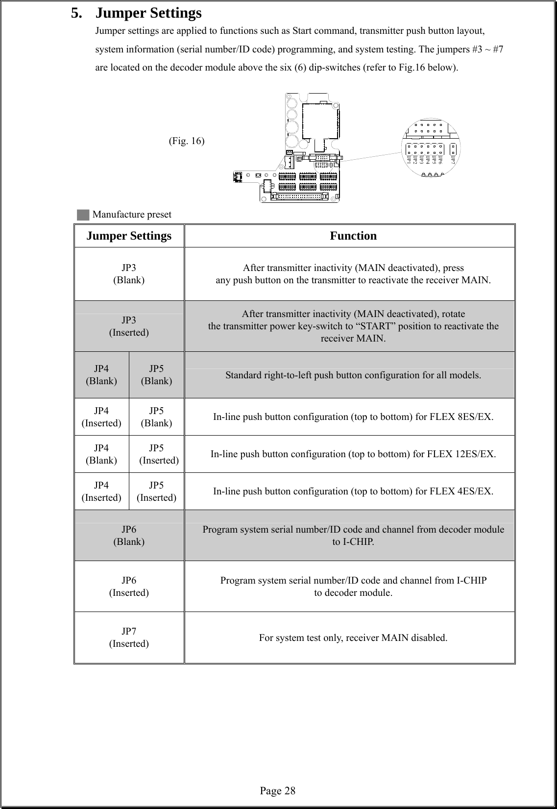
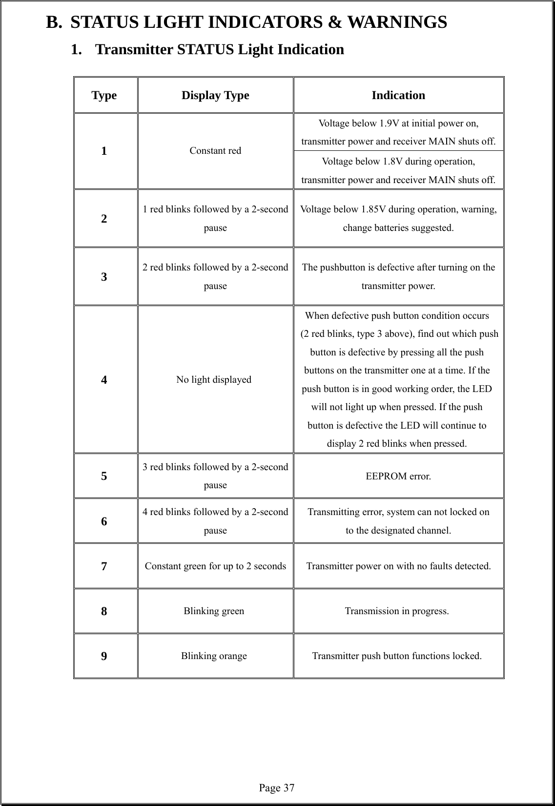
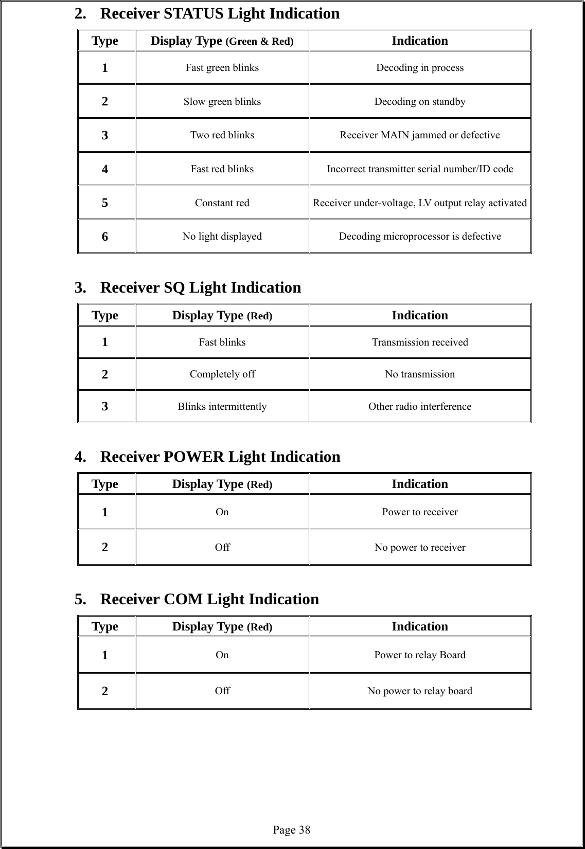
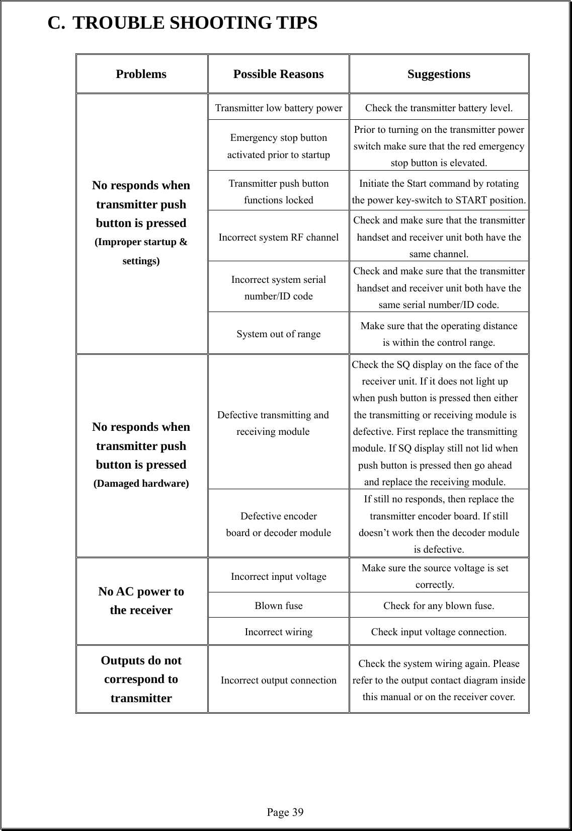
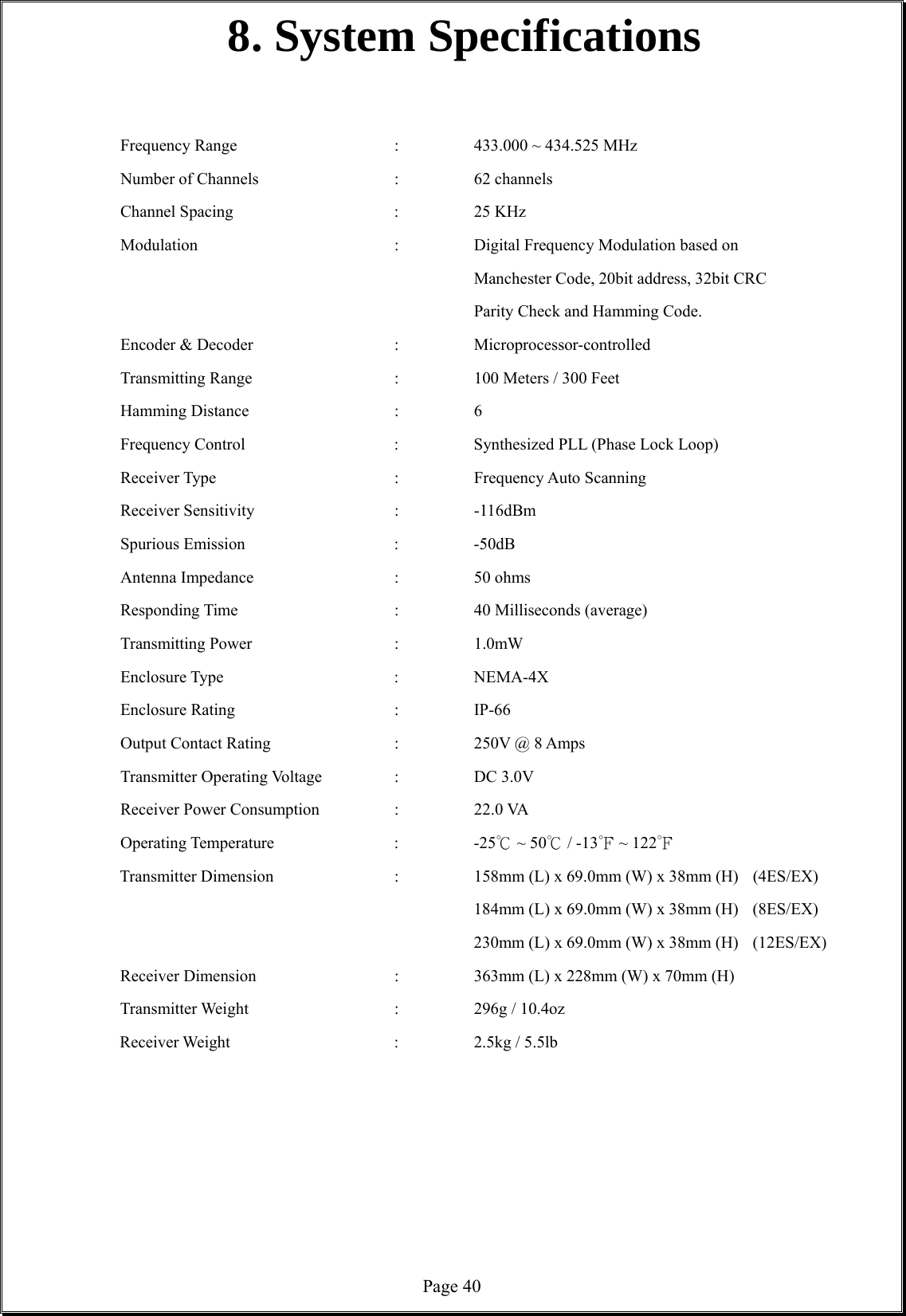
User Manual
Discussion / Help
Navigation