Advanced Radiotech ARCFLEXEX Industrial radio remote control systems User Manual Flex EX User s Manual
Advanced Radiotech Corporation Industrial radio remote control systems Flex EX User s Manual
User manual

FLEXEXSeries
User’s Manual
CE Version

Page 1
Table of Contents
Page
1. Introduction 3
2. Radio Controlled Safety 4
3. General System Information
A. Transmitter Handset
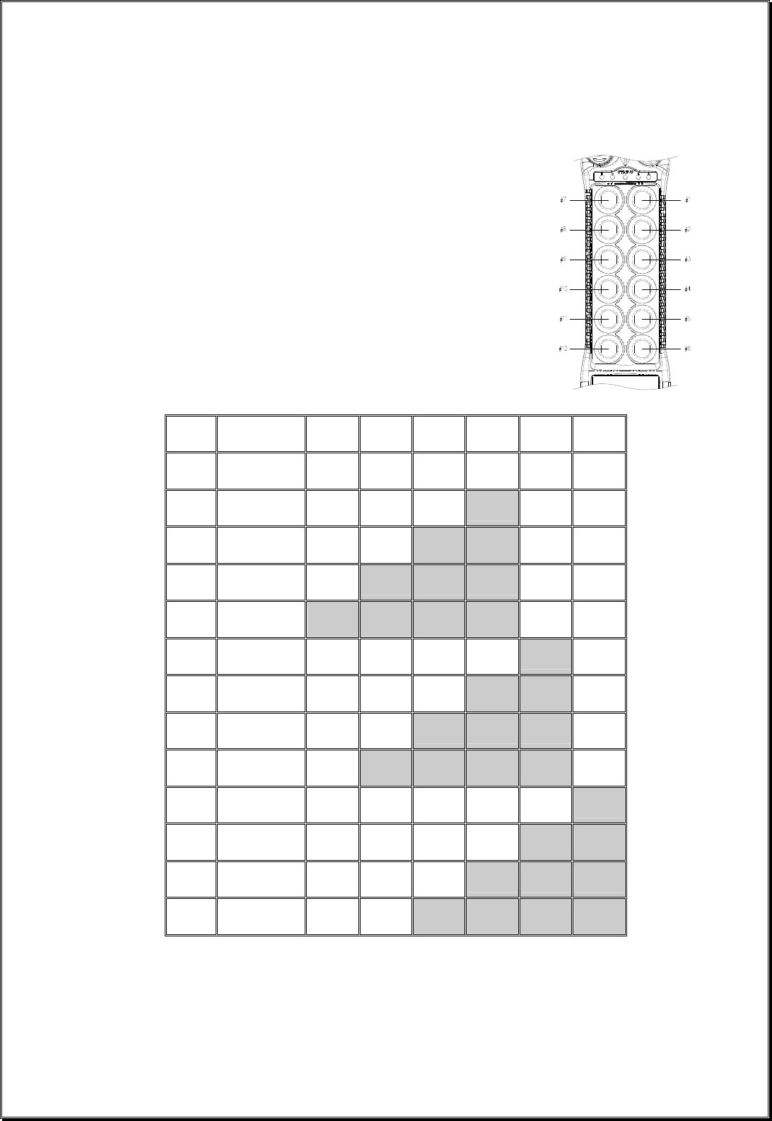
1. External Illustration (Standard Push Button Configuration) 5
2. Internal Illustration 6
B. Receiver Unit
1. External Illustration 7
2. Internal Illustration 8
4. Function Settings
A. Transmitter Handset
1. System Channel Settings 9
2. Push Button Functions with LED Displays
a. Standard Push Button Configuration (Transmitter Toggle) 10
b. Standard Push Button Configuration (A/B Selector) 11~13
c. Inline Push Button Configuration (Transmitter Toggle) 14
d. Inline Push Button Configuration (A/B Selector) 15~17
3. Channel Change via Push Buttons 18
4. Program 4-digit Security Code 19
5. I-Chip 20
B. Receiver Unit
1. System Channel Settings 21
2. Output Relay Configurations
a. Output Relay Types 22
b. Output Relay Action at 2nd Speed 22~23
c. ON/OFF Push Button Function 23
d. Magnet ON/OFF Push Button Function 24
e. Brake Function 24
f. External Warning Function 24
g. Momentary Contact 24
h. Toggled Contact 24
i. 3rd Speed Push Button Function 24

Page 2
j. Auxiliary STOP Push Button Function 25
k. Pitch & Catch Function 25
3. Receiver Auto-Scanning Settings 25
4. Dip-switch Settings
a. Interlocked Functions 26
b. Non-interlocked Functions 27
5. Jumpers Settings 28
6. I-Chip Programming Port 29
7. Voltage Settings 29
5. System Channels Table 30
6. Receiver Installation
A. Output Relay Contact Diagram 31
B. Pre-Installation Precautions 32
C. Step-By-Step Installation 32~33
D. System Testing 33
7. Operating Procedure
A. Transmitter Operation
1. General Operating Procedure 34~35
2. A/B Selector Push Button Operating Procedure 35
3. 3rd Speed Push Button Operating Procedure 35
4. Pitch & Catch Operating Procedure 36
5. Automatic Channel Scanning Operating Procedure 36
6. Changing Transmitter Batteries 36
B. Status Light Indicators & Warnings
1. Transmitter STATUS Light Indication 37
2. Receiver STATUS Light Indication 38
3. Receiver SQ Light Indication 38
4. Receiver POWER Light Indication 38
5. Receiver COM Light Indication 38
C. Trouble Shooting Tips 39
8. System Specifications 40
9. EU Declaration of Conformity 41

Page 3
1. Introduction
The FLEX radio remote control systems are designed for control of industrial equipment and machinery
such as overhead traveling cranes, jib cranes, gantry cranes, tower cranes, electric hoists, winches, monorails,
conveyor belts, mining equipment and other material handling equipment where wireless control is preferred.
Each FLEX system consists of a transmitter handset and receiver unit. Other standard-equipped
accessories include transmitter waist belt, spare transmitter power key, clear vinyl pouch, “AA” alkaline
batteries, compass direction decal sheet and user’s manual.
List of notable features include:
* 62 user-programmable channels – Advanced synthesized RF controls with 62 built-in channels, no
more fixed channel and fragile quartz crystals to break.
* Automatic channel scanning receiver – No more hassle of climbing up the crane to change receiver
channels.
* Over one million unique ID codes (20bit) – Each and every Flex system has its own unique ID codes
and serial number, never repeats.
* Advanced controls – The Flex system utilizes advanced microprocessor controls with 32bit CRC and
Hamming Code, which provide ultra fast, safe, precise, and error-free encoding and decoding.
* Unique I-CHIP design – The I-CHIP functions in a way that is very similar to SIM card used on
mobile phones, with the ability to transfer system information and settings from one transmitter to
another without the hassle of resetting the spares.
* Reliable push buttons – The in-house designed push buttons with gold-plated contacts are rated for
more than one million press cycles.
* Low power consumption – Requires only two “AA” Alkaline batteries for more than 150 hours of
operating time between replacements.
* Ultra-durable nylon and fiberglass composite enclosures – Highly resistance to breakage and
deformation even in the most abusive environments.
* Full compliance – All systems are fully complied with the FCC Part-15 Rules, European Directives
(Safety, EMC, R&TTE, Machinery) and Industry Canada Specifications (IC).

Page 4
2. Radio Controlled Safety
Flex radio remote control system should be operated by persons with sufficient amount of knowledge
and skill in crane operation and safety. Persons being trained to operate a radio remote controlled crane should
possess the knowledge of all hazards peculiar to radio remote controlled crane operation, ability to judge
distance and moving objects, equipment capacity and radio remote controlled safety rules. Radio remote
controlled cranes should not be operated by any person with insufficient eyesight, hearing, illness, and under
influence of drugs and medications that may cause loss of crane control.
Below are some general operating safety tips that should be strictly followed when operating a radio
remote controlled crane.
1. Prior to crane operation always check the transmitter handset for any damage that might inhibit proper
crane operation.
2. Always check if the red emergency stop button is working properly prior to crane operation.
3. Check the Status LED on the transmitter for any signs of low battery power (refer to page 37).
4. Check the Status LED on the transmitter for any signs of irregularities (refer to page 37).
5. The crane limit switches should be checked prior to crane operation or at the beginning of each shift.
When checking limit switches the hoist should be centered over an area free of personnel and
equipment.
6. If the power to the crane is removed, the operator should turn off the transmitter power immediately
until the power to the crane is restored.
7. If the crane fails to respond properly to operator’s command the operator should stop operation, turn
the transmitter power off, and then report the condition to their supervisor.
8. The transmitter power should be turned off after each use. If the transmitter handset is not in use always
turn the power off and stored it in a safe or designated location. Never leave the transmitter handset
unattended in the working area.
9. Make sure the system is not set to the same channel as any other Flex systems in use within a distance
of 300 meters (900 feet).
10. Never operate a crane or equipment with two transmitter handsets at the same time unless they are
programmed with “Pitch & Catch” function. For information on the “Pitch & Catch” feature, please
refer to page 25 and page 36 of this manual.
CAUTION
RISK OF EXPLOSION IF BATTERY IS PLACED BY AN INCORRECT TYPE.
DISPOSE OF USED BATTERIES ACCORDING TO THE INSTRUCTIONS.
Page 5
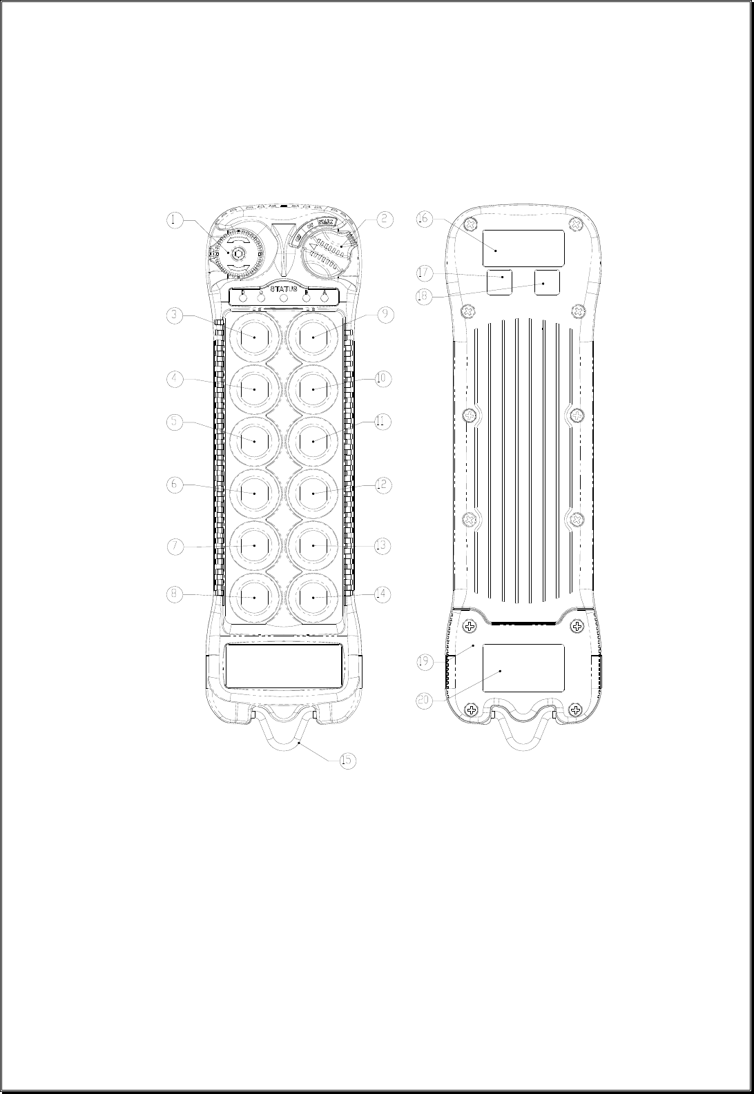
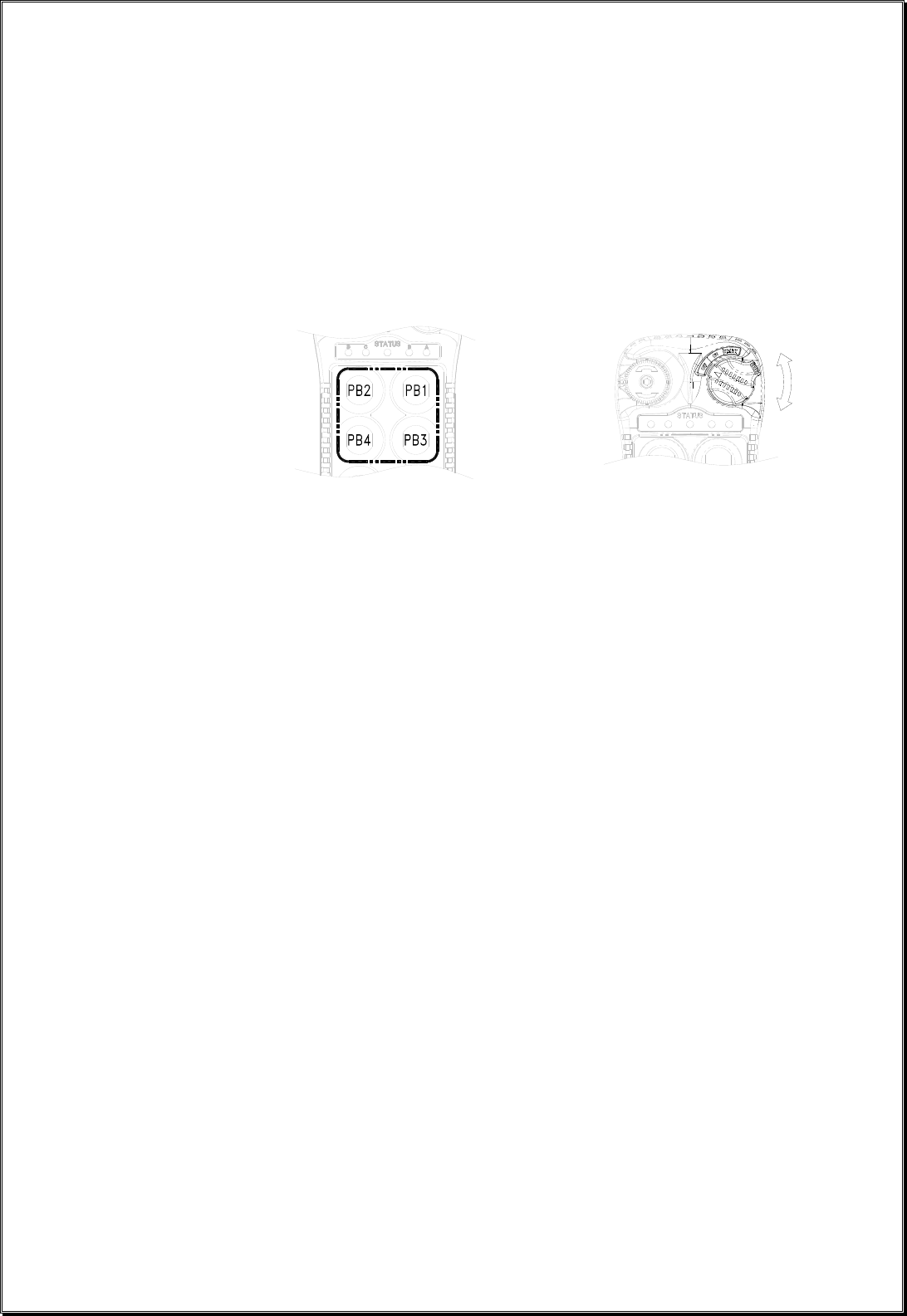
3. General System Information
A. TRANSMITTER HANDSET
1. External Illustration (Standard Push Button Configuration)
(Fig. 01) (Fig. 02)
1. Emergency Stop Button 8. Push Button #12 15. Strap Ring
2. Removable Power Key Switch 9. Push Button #1 16. System Information
3. Push Button #2 10. Push Button #3 17. System Channel
4. Push Button #4 11. Push Button #5 18. Crane Number
5. Push Button #6 12. Push Button #7 19. Battery Cover
6. Push Button #8 13. Push Button #9 20. Approval Information
7. Push Button #10 14. Push Button #11
Page 6
7
8
9
6
5
4
3
1
2
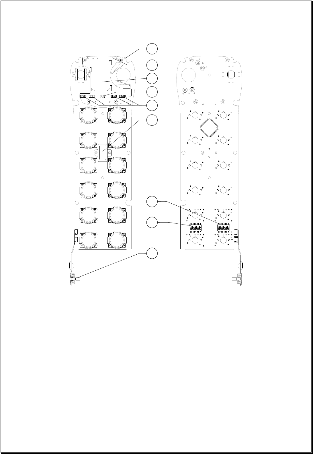
2. Internal Illustration
(Fig. 03) (Fig. 04)
1. Encoder Board 6. I-CHIP
2. Arial Antenna 7. Function Dip-Switch
3. Transmitting Module 8. Channel Dip-Switch
4. Status LED Display 9. Battery Contact Mechanism
5. Function LED Displays
Page 7
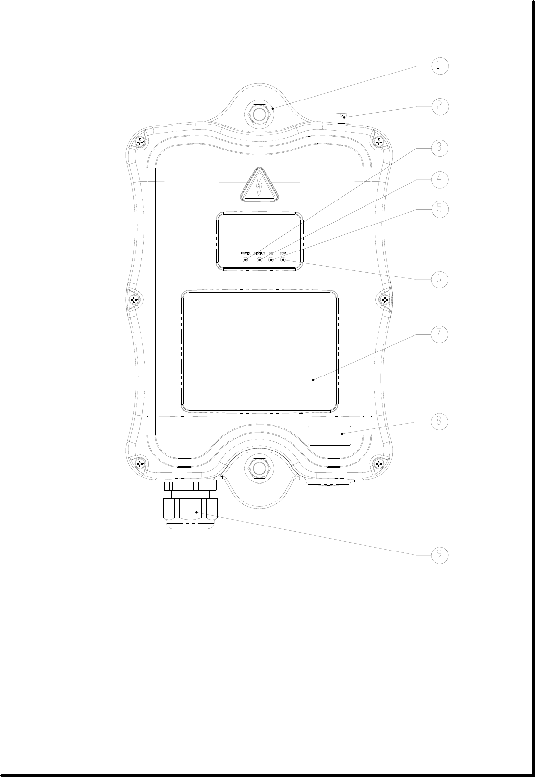
B. RECEIVER UNIT
1. External Illustration
(Fig. 05)
1. Shock Mount 6. COM LED Display
2. External Antenna Jack 7. Output Contact Diagram
3. Power LED Display 8. System Information
4. Status LED Display 9. Cord Grip
5. SQ LED Display

Page 8
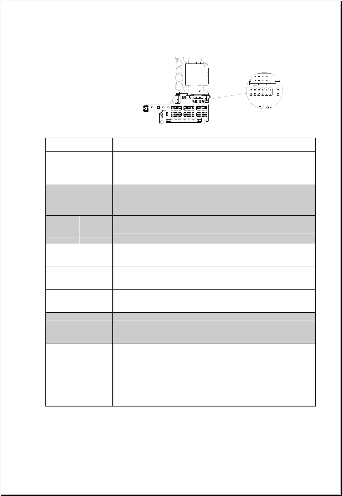
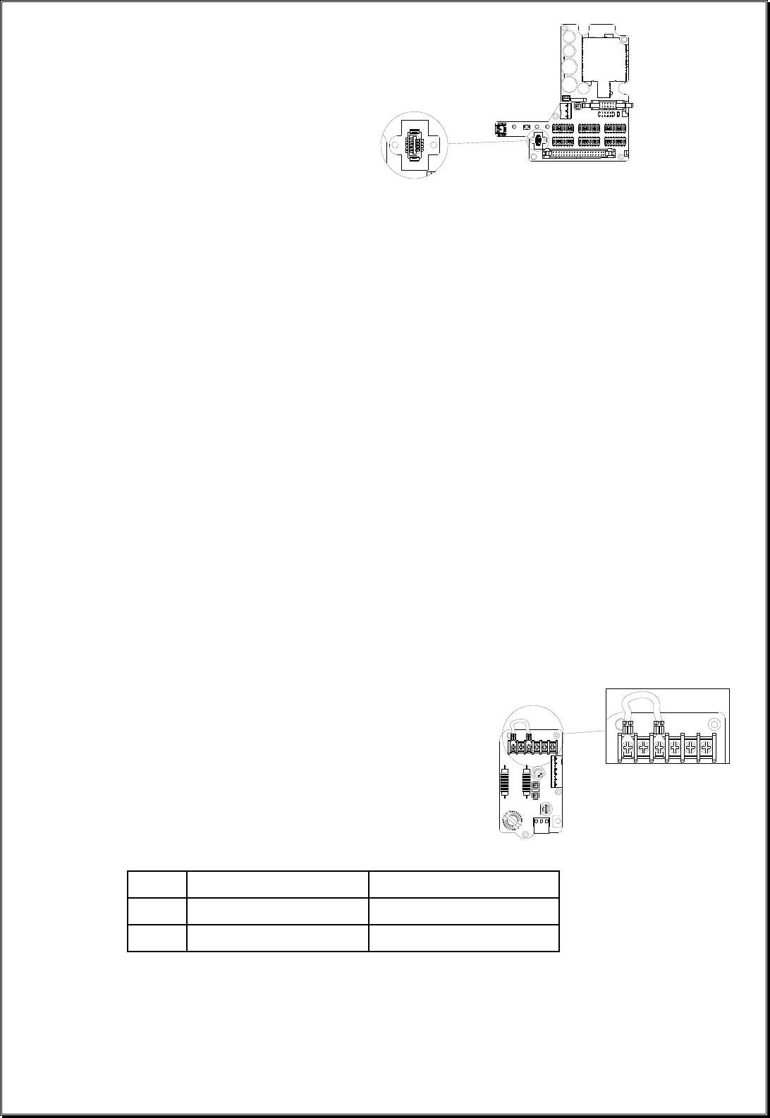
2. Internal Illustration
(Fig. 06)
1. AC Line Filter 4. Decoder Module
2. Power Transformer 5. Output Relay Board
3. Receiving Module
Page 9
71423 56 8
CHANNEL
71 423 56 8
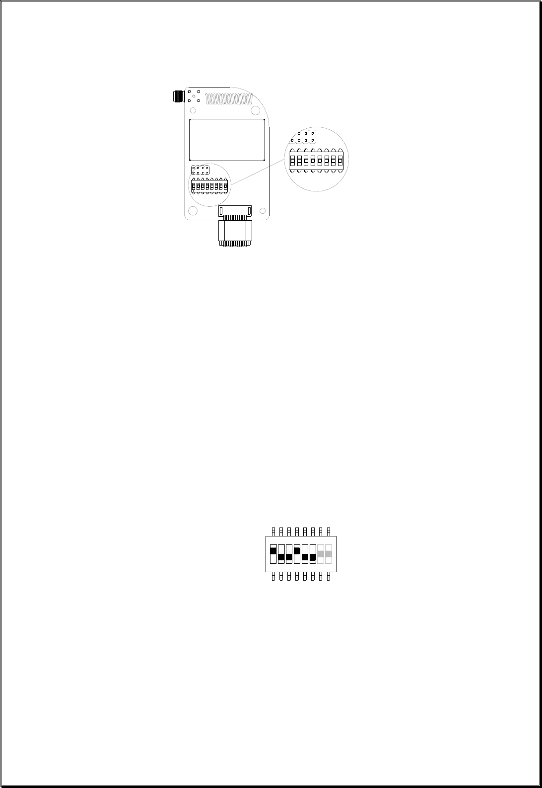
4. Function Settings
A. TRANSMITTER HANDSET
1. System Channel Settings
(Fig. 07)
Set the transmitter channel by adjusting the channel dip-switch located on the backside of the transmitter
encoder board (refer to Fig. 07 above). Only the first six (6) positions are used for channel programming
(refer to Fig. 08 below). The system channels table located on page 30 illustrates which dip-switch
setting corresponds to which channel. Once the transmitter channel is altered do make sure to change
receiver channel as well. The channel on both transmitter and receiver must be identical in order for
system to work. To change receiver channel please refer to page 21.
Example: Top slot → “1”
(Fig. 08) Bottom slot → “0”
The above dip-switch setting “1 0 0 1 0 0” corresponds to “channel 36” in the system channels table on
page 30.
Page 10
LED 1LED 2
LED 3
LED 4
52134 867
FUNCTION
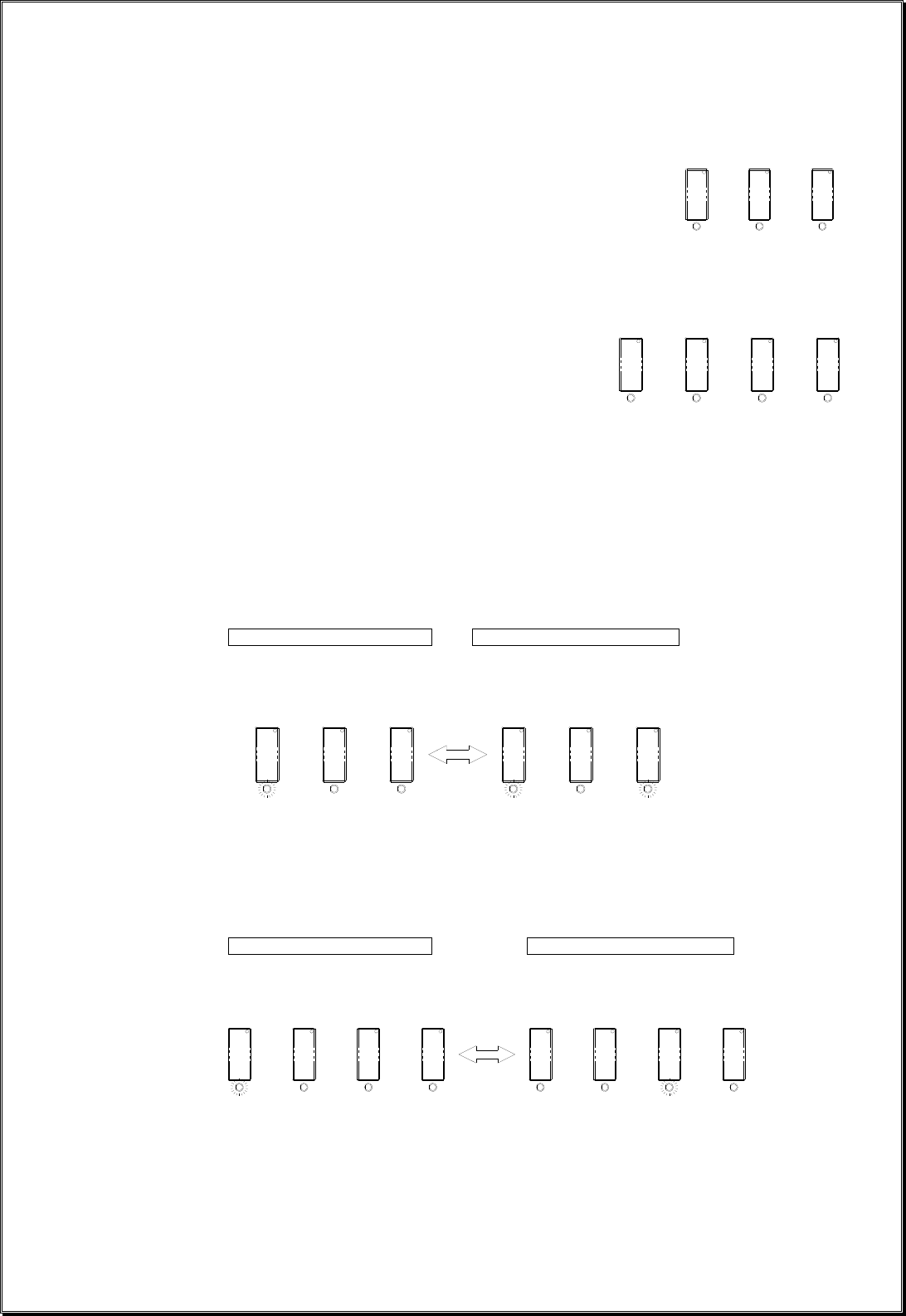
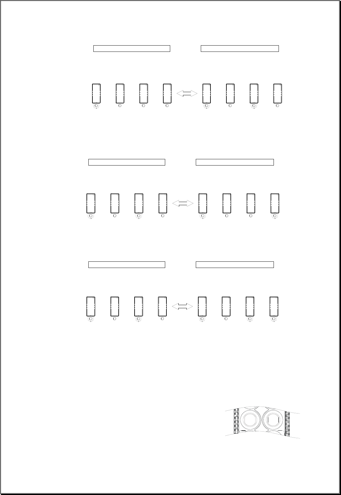
2. Push Button Functions with LED Displays
A. Standard Push Button (Transmitter Toggle)
Set transmitter toggle (latching output relay) function by adjusting the 8-position function
dip-switch located on the backside of the transmitter encoder board (refer to Fig. 09 below).
The LED 1 through LED 4 shown inside the shaded box (see below) illustrates which LED on
the transmitter will light up when the designated push button (PB7 ~ PB12) is pressed.
(Fig. 09)
DIP PB7 PB8 PB9 PB10 PB11 PB12
1 00000000 Normal Normal Normal Normal Normal Normal
2 00001001 Normal Normal Normal LED 4 Normal Normal
3 00001010 Normal Normal LED 3 LED 4 Normal Normal
4 00001011 Normal LED 2 LED 3 LED 4 Normal Normal
5 00001100 LED 1 LED 2 LED 3 LED 4 Normal Normal
6 00001101 Normal Normal Normal Normal Normal LED 4
7 00001110 Normal Normal Normal Normal LED 3 LED 4
8 00001111 Normal Normal Normal LED 2 LED 3 LED 4
9 00010000 Normal Normal LED 1 LED 2 LED 3 LED 4
* PB7…PB12 → Push button number
* Normal → Normal momentary contact
* LED 1…LED 4 → Transmitter toggled with designated LED Display
Page 11
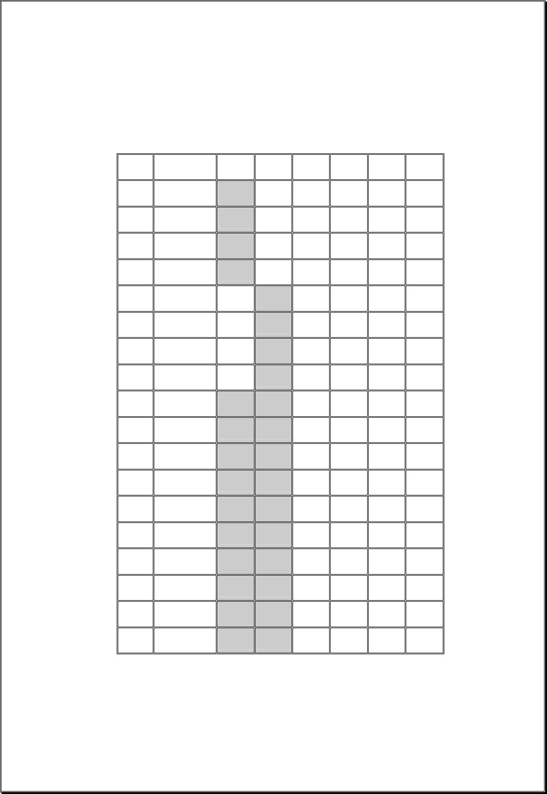
B. Standard Push Button Configuration (A/B Selector)
There are four (4) different types of A/B selector sequence available on the Flex system.
Choose the one that is most suitable for your application.
Type-A selector sequence : A → B → A → B …
Type-B selector sequence : Off → A → B → Off → A → B …
Type-C selector sequence : A → B → A+B → A → B → A+B …
Type-D selector sequence : Off → A → B → A+B → Off → A → B → A+B …
DIP PB7 PB8 PB9 PB10 PB11 PB12
10 00101111 A/1&2 Normal Normal Normal Normal Normal
11 00110000 B/1&2 Normal Normal Normal Normal Normal
12 00110001 C/1&2 Normal Normal Normal Normal Normal
13 00110010 D/1&2 Normal Normal Normal Normal Normal
14 00110011 Normal A/3&4 Normal Normal Normal Normal
15 00110100 Normal B/3&4 Normal Normal Normal Normal
16 00110101 Normal C/3&4 Normal Normal Normal Normal
17 00110110 Normal D/3&4 Normal Normal Normal Normal
18 00110111 A/1&2 A/3&4 Normal Normal Normal Normal
19 00111000 A/1&2 B/3&4 Normal Normal Normal Normal
20 00111001 A/1&2 C/3&4 Normal Normal Normal Normal
21 00111010 A/1&2 D/3&4 Normal Normal Normal Normal
22 00111011 B/1&2 B/3&4 Normal Normal Normal Normal
23 00111100 B/1&2 C/3&4 Normal Normal Normal Normal
24 00111101 B/1&2 D/3&4 Normal Normal Normal Normal
25 00111110 C/1&2 C/3&4 Normal Normal Normal Normal
26 00111111 C/1&2 D/3&4 Normal Normal Normal Normal
27 01000000 D/1&2 D/3&4 Normal Normal Normal Normal
* PB7…PB12 → Push button number
* Normal → Normal momentary contact
* A/1&2…D/3&4 → A/B Selector type with designated LED Display (LED 1&2 or LED 3&4)
Page 12
DIP PB7 PB8 PB9 PB10 PB11 PB12
28 01000001 Normal Normal A/1&2 Normal Normal Normal
29 01000010 Normal Normal B/1&2 Normal Normal Normal
30 01000011 Normal Normal C/1&2 Normal Normal Normal
31 01000100 Normal Normal D/1&2 Normal Normal Normal
32 01000101 Normal Normal Normal A/3&4 Normal Normal
33 01000110 Normal Normal Normal B/3&4 Normal Normal
34 01000111 Normal Normal Normal C/3&4 Normal Normal
35 01001000 Normal Normal Normal D/3&4 Normal Normal
36 01001001 Normal Normal A/1&2 A/3&4 Normal Normal
37 01001010 Normal Normal A/1&2 B/3&4 Normal Normal
38 01001011 Normal Normal A/1&2 C/3&4 Normal Normal
39 01001100 Normal Normal A/1&2 D/3&4 Normal Normal
40 01001101 Normal Normal B/1&2 B/3&4 Normal Normal
41 01001110 Normal Normal B/1&2 C/3&4 Normal Normal
42 01001111 Normal Normal B/1&2 D/3&4 Normal Normal
43 01010000 Normal Normal C/1&2 C/3&4 Normal Normal
44 01010001 Normal Normal C/1&2 D/3&4 Normal Normal
45 01010010 Normal Normal D/1&2 D/3&4 Normal Normal
* PB7…PB12 → Push button number
* Normal → Normal momentary contact
* A/1&2…D/3&4 → A/B Selector type with designated LED Display (LED 1&2 or LED 3&4)
Page 13
DIP PB7 PB8 PB9 PB10 PB11 PB12
46 01010011 Normal Normal Normal Normal A/1&2 Normal
47 01010100 Normal Normal Normal Normal B/1&2 Normal
48 01010101 Normal Normal Normal Normal C/1&2 Normal
49 01010110 Normal Normal Normal Normal D/1&2 Normal
50 01010111 Normal Normal Normal Normal Normal A/3&4
51 01011000 Normal Normal Normal Normal Normal B/3&4
52 01011001 Normal Normal Normal Normal Normal C/3&4
53 01011010 Normal Normal Normal Normal Normal D/3&4
54 01011011 Normal Normal Normal Normal A/1&2 A/3&4
55 01011100 Normal Normal Normal Normal A/1&2 B/3&4
56 01011101 Normal Normal Normal Normal A/1&2 C/3&4
57 01011110 Normal Normal Normal Normal A/1&2 D/3&4
58 01011111 Normal Normal Normal Normal B/1&2 B/3&4
59 01100000 Normal Normal Normal Normal B/1&2 C/3&4
60 01100001 Normal Normal Normal Normal B/1&2 D/3&4
61 01100010 Normal Normal Normal Normal C/1&2 C/3&4
62 01100011 Normal Normal Normal Normal C/1&2 D/3&4
63 01100100 Normal Normal Normal Normal D/1&2 D/3&4
* PB7…PB12 → Push button number
* Normal → Normal momentary contact
* A/1&2…D/3&4 → A/B Selector type with designated LED Display (LED 1&2 or LED 3&4)
Page 14
C. Inline Push Button Configuration (Transmitter Toggle)
The push button arrangement for inline push button setup starts from top to bottom and then
from right column to left column (refer to Fig. 10 below). To set inline push button
configuration please refer to JP4 and JP5 jumpers setting on page 28. With inline push buttons
configuration, PB1 & PB2 still corresponds to output relay K1~K4, PB3 & PB4 corresponds to
relay K5~K8, etc…
(Fig. 10)
DIP PB7 PB8 PB9 PB10 PB11 PB12
64 00000000 Normal Normal Normal Normal Normal Normal
65 00000101 Normal Normal Normal LED 4 Normal Normal
66 00010100 Normal Normal LED 3 LED 4 Normal Normal
67 00010101 Normal LED 2 LED 3 LED 4 Normal Normal
68 00010110 LED 1 LED 2 LED 3 LED 4 Normal Normal
69 00001001 Normal Normal Normal Normal LED 4 Normal
70 00010111 Normal Normal Normal LED 3 LED 4 Normal
71 00011000 Normal Normal LED 2 LED 3 LED 4 Normal
72 00011001 Normal LED 1 LED 2 LED 3 LED 4 Normal
73 00001101 Normal Normal Normal Normal Normal LED 4
74 00011010 Normal Normal Normal Normal LED 3 LED 4
75 00011011 Normal Normal Normal LED 2 LED 3 LED 4
76 00011100 Normal Normal LED 1 LED 2 LED 3 LED 4
* PB7…PB12 → Push button number
* Normal → Normal momentary contact
* LED 1…LED 4 → Transmitter toggled with designated LED Display
Page 15
D. Inline Push Button Configuration (A/B Selector)
There are four (4) different types of A/B selector sequence available on the Flex system.
Choose the one that is most suitable for your application.
Type-A selector sequence : A → B → A → B …
Type-B selector sequence : Off → A → B → Off → A → B …
Type-C selector sequence : A → B → A+B → A → B → A+B …
Type-D selector sequence : Off → A → B → A+B → Off → A → B → A+B …
DIP PB9 PB10 PB11 PB12
77 01110011 A/1&2 Normal Normal Normal
78 01110100 B/1&2 Normal Normal Normal
79 01110101 C/1&2 Normal Normal Normal
80 01110110 D/1&2 Normal Normal Normal
81 00110011 Normal A/3&4 Normal Normal
82 00110100 Normal B/3&4 Normal Normal
83 00110101 Normal C/3&4 Normal Normal
84 00110110 Normal D/3&4 Normal Normal
85 01110111 A/1&2 A/3&4 Normal Normal
86 01111000 A/1&2 B/3&4 Normal Normal
87 01111001 A/1&2 C/3&4 Normal Normal
88 01111010 A/1&2 D/3&4 Normal Normal
89 01111011 B/1&2 B/3&4 Normal Normal
90 01111100 B/1&2 C/3&4 Normal Normal
91 01111101 B/1&2 D/3&4 Normal Normal
92 01111110 C/1&2 C/3&4 Normal Normal
93 01111111 C/1&2 D/3&4 Normal Normal
94 10000000 D/1&2 D/3&4 Normal Normal
* PB7…PB12 → Push button number
* Normal → Normal momentary contact
* A/1&2…D/3&4 → A/B Selector type with designated LED Display (LED 1&2 or LED 3&4)

Page 16
DIP PB9 PB10 PB11 PB12
95 10000001 Normal A/1&2 Normal Normal
96 10000010 Normal B/1&2 Normal Normal
97 10000011 Normal C/1&2 Normal Normal
98 10000100 Normal D/1&2 Normal Normal
99 01000101 Normal Normal A/3&4 Normal
100 01000110 Normal Normal B/3&4 Normal
101 01000111 Normal Normal C/3&4 Normal
102 01001000 Normal Normal D/3&4 Normal
103 10000101 Normal A/1&2 A/3&4 Normal
104 10000110 Normal A/1&2 B/3&4 Normal
105 10000111 Normal A/1&2 C/3&4 Normal
106 10001000 Normal A/1&2 D/3&4 Normal
107 10001001 Normal B/1&2 B/3&4 Normal
108 10001010 Normal B/1&2 C/3&4 Normal
109 10001011 Normal B/1&2 D/3&4 Normal
110 10001100 Normal C/1&2 C/3&4 Normal
111 10001101 Normal C/1&2 D/3&4 Normal
112 10001110 Normal D/1&2 D/3&4 Normal
* PB7…PB12 → Push button number
* Normal → Normal momentary contact
* A/1&2…D/3&4 → A/B Selector type with designated LED Display (LED 1&2 or LED 3&4)
Page 17
DIP PB9 PB10 PB11 PB12
113 10001111 Normal Normal A/1&2 Normal
114 10010000 Normal Normal B/1&2 Normal
115 10010001 Normal Normal C/1&2 Normal
116 10010010 Normal Normal D/1&2 Normal
117 01010111 Normal Normal Normal A/3&4
118 01011000 Normal Normal Normal B/3&4
119 01011001 Normal Normal Normal C/3&4
120 01011010 Normal Normal Normal D/3&4
121 10010011 Normal Normal A/1&2 A/3&4
122 10010100 Normal Normal A/1&2 B/3&4
123 10010101 Normal Normal A/1&2 C/3&4
124 10010110 Normal Normal A/1&2 D/3&4
125 10010111 Normal Normal B/1&2 B/3&4
126 10011000 Normal Normal B/1&2 C/3&4
127 10011001 Normal Normal B/1&2 D/3&4
128 10011010 Normal Normal C/1&2 C/3&4
129 10011011 Normal Normal C/1&2 D/3&4
130 10011100 Normal Normal D/1&2 D/3&4
* PB7…PB12 → Push button number
* Normal → Normal momentary contact
* A/1&2…D/3&4 → A/B Selector type with designated LED Display (LED 1&2 or LED 3&4)
Page 18
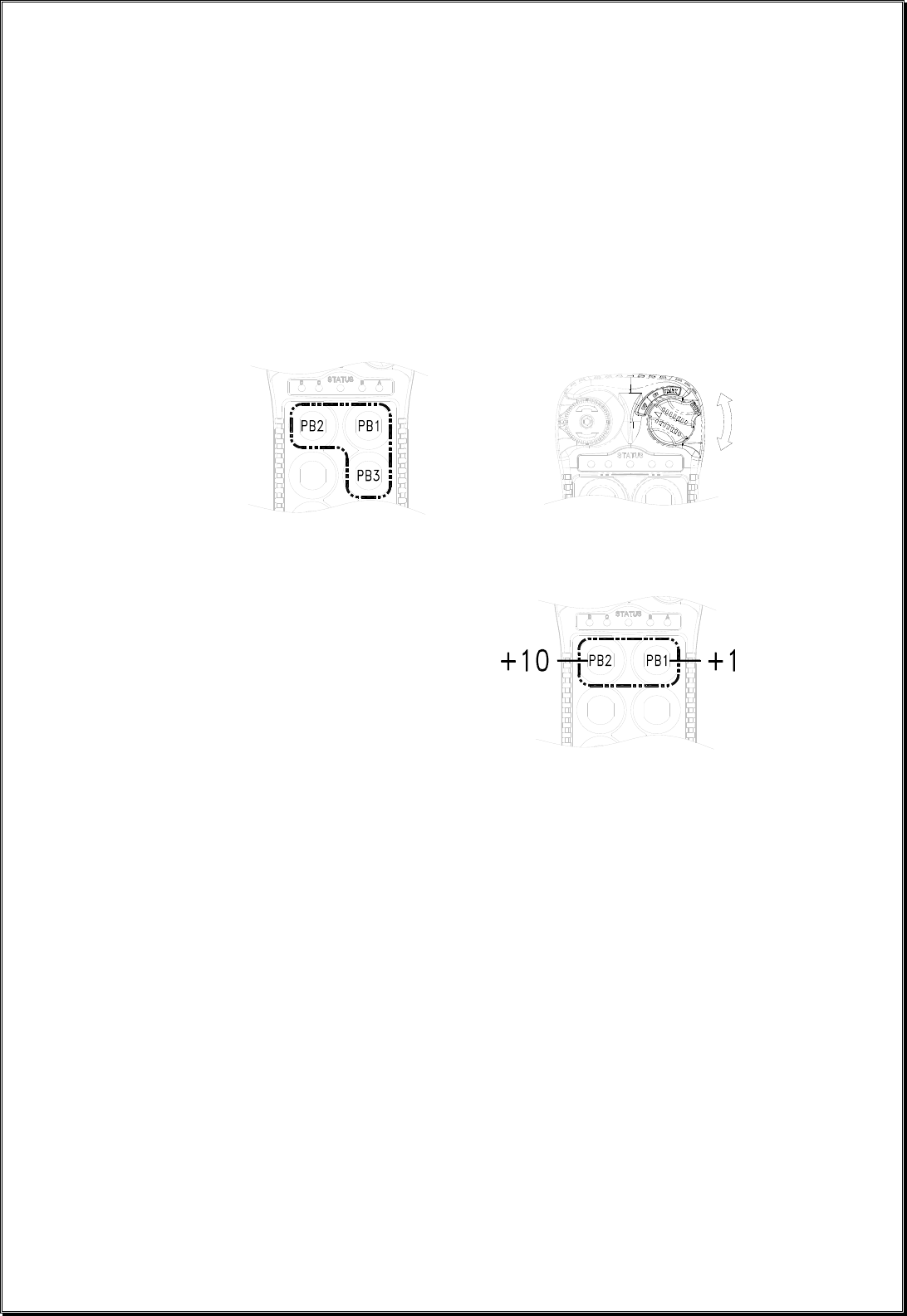
3. Channel Change via Push Buttons
Other than CHANNEL dip-switch on the encoder board, the transmitter channel can also be changed
directly on the push buttons. Please refer to the instruction below on how to change transmitter channel
via push buttons.
a. Press and hold PB1, PB2 and PB3 and rotate the power key to START position at the same time. A
series of green and red blinks will appear on the Status LED showing the current channel setting. A
green blink represents the tens (+10) and a red blink represents the units (+1).
Examples: 2 green blinks followed by 5 red blinks represents channel 25.
6 red blinks represents channel 06.
+
b. Select new channel by pressing PB1 and PB2 on the transmitter. Press PB1 to increment the units
(+1) and PB2 to increment the tens (+10).
Examples: Press PB2 two times and then PB1 four times will give you channel 24.
Press PB1 nine times with give you channel 09.
c. When finished, the newly selected channel will appear on the Status LED via series of green and
red blinks again.
d. Exit the channel programming by turning off the transmitter power.
e. Make sure the receiver channel is set identical to the transmitter. Please refer to page 21 and page
36 on how to change receiver channel.
f. Please note that when the CHANNEL dip-switch inside the transmitter is changed, the priority will
revert back to the new channel set on the CHANNEL dip-switch.
g. Please note that when channel is set beyond channel 62 via PB1 and PB2 (i.e. channel 63, 68, 88,
etc…), the system will recognize it as channel 62.
Page 19
4. Program 4-digit Security Code
Prior to rotating the transmitter power key-switch to START position to begin operation, you must first
enter a 4-digit security code in order to proceed further. When this 4-digit security code is input correctly
after turning on the transmitter power, a green light will appear on the Status LED... proceed to START
activation. If this 4-digit security code is input incorrectly, an orange light will appear on the Status
LED… system locked. If this occurs, then you must reset the e-stop button and input the correct 4-digit
code. Please refer to the instruction below on how to program the 4-digit security code.
a. Press and hold PB1, PB2, PB3 and PB4 and rotate the power key to START position at the same
time.
+
b. A constant orange light will appear on the Status LED telling you that you are in the security code
programming mode.
c. For newly purchased system with the security code function deactivated (default setting), press
PB1 four times (1111) to activate the security code function. At this time the Status LED on the
transmitter will blink orange slowly telling you that the 4 digits entered is correct. Then select your
own 4-digit security code by pressing PB1, PB2, PB3 or PB4 on the transmitter (four presses
randomly). At this time a fast orange blinks is displayed on the Status LED telling you to
reconfirm the 4-digit security code you have just entered. A green light will appear once you have
re-entered the same 4-digit security code again (programming completed). If red light is shown on
the Status LED after you have re-entered the security code (incorrect input), then you must reset
the transmitter power and then repeat step a, b and c again.
Steps: Press and hold PB1~PB4 and rotate power key to START position → constant orange →
press PB1 four times (for new systems) or 4-digit security code → slow orange blinks → enter the
new 4-digit security code → fast orange blinks → re-enter the same 4-didgit security code again
→ green light.
d. If you wish to cancel the security code function, then repeat a, b, c above and press PB1 four times
as your new security code (security code function disabled).
e. If you do not remember the 4-digit security code, then you must contact your dealer or distributor
for further assistance.
Page 20
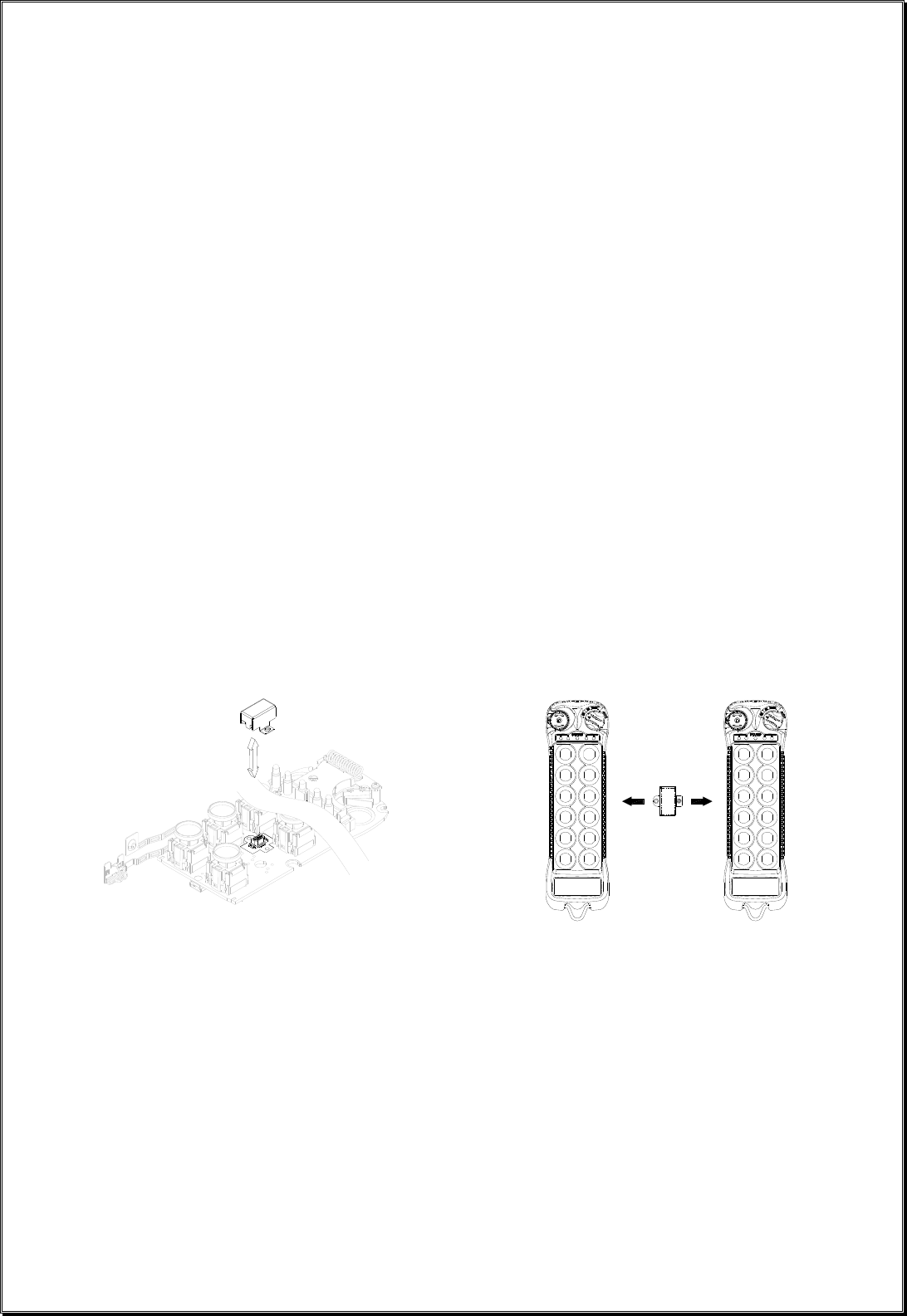
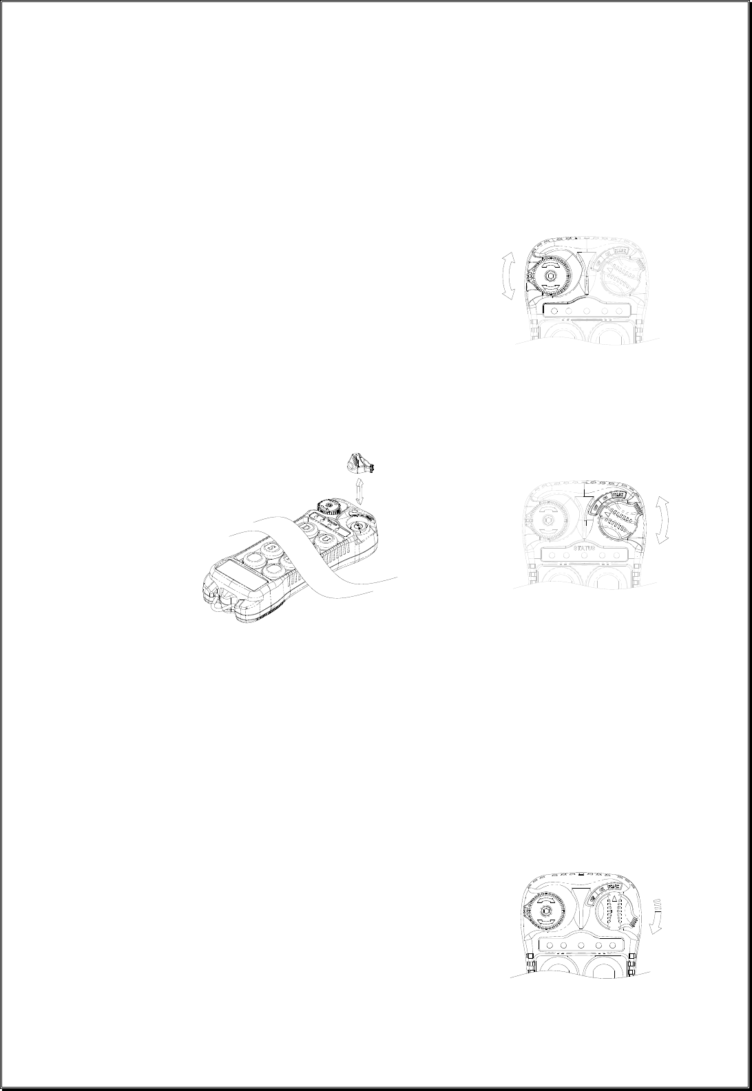
5. I-Chip
I-CHIP functioned in a way that is very similar to a SIM card inside a mobile phone, which stores
information such as your phone number, account number, phone book and other settings. I-CHIP works
exactly the same way, as it stores information such as system serial number/ID code, channel and push
button configurations.
When replacing a transmitter handset, just take the I-CHIP out of the old transmitter and install it into the
new one (refer to Fig. 11 below). The new transmitter handset will then operate according to the
information stored in the I-CHIP unless the settings on both Channel and Function dip-switch are
changed thereafter. Basically the microprocessor will operate according to the last setting change either
on I-CHIP or the dip-switches.
For safety purposes, system serial number/ID code stored inside the I-CHIP can not be changed directly
on the transmitter encoder board. Only channels and push button configurations can be changed directly
on the encoder board via Channel and Function dip-switches. There are only two ways that you can
change transmitter serial number/ID code; 1) via I-CHIP programming port located on the decoder
module inside the receiver unit, please refer to page 29 on how to program the I-CHIP (serial number/ID
code) via receiver unit; 2) via an external I-CHIP programmer or duplicator unit available from the
factory. Please ask your local dealers for assistance if your system requires serial number/ID code
adjustments.
(Fig. 11)
Page 21
71 423 56 8
INTEXT 123 56 847
B. RECEIVER UNIT
1. System Channel Settings
(Fig. 12)
Even though Flex system is equipped with automatic channel scanning receiver, the user can also set
the receiver channel manually. Please refer to page 36 on how automatic channel scanning receiver
works.
Set the receiver channel by adjusting the channel dip-switch located on the receiver module (refer to
Fig. 12 above), only the first six (6) positions are used for channel programming (refer to Fig. 13
below). The system channels table located on page 30 illustrates which dip-switch setting corresponds
to which channel. Once the receiver channel is altered do make sure to change transmitter channel as
well. The channel on both transmitter and receiver must be identical in order for system to work. To
change transmitter channel please refer to page 9.
Example: Top slot → “1”
(Fig. 13) Bottom slot → “0”
The above dip-switch setting “1 0 0 1 0 0” corresponds to “channel 36” in the system channels table
on page 30.
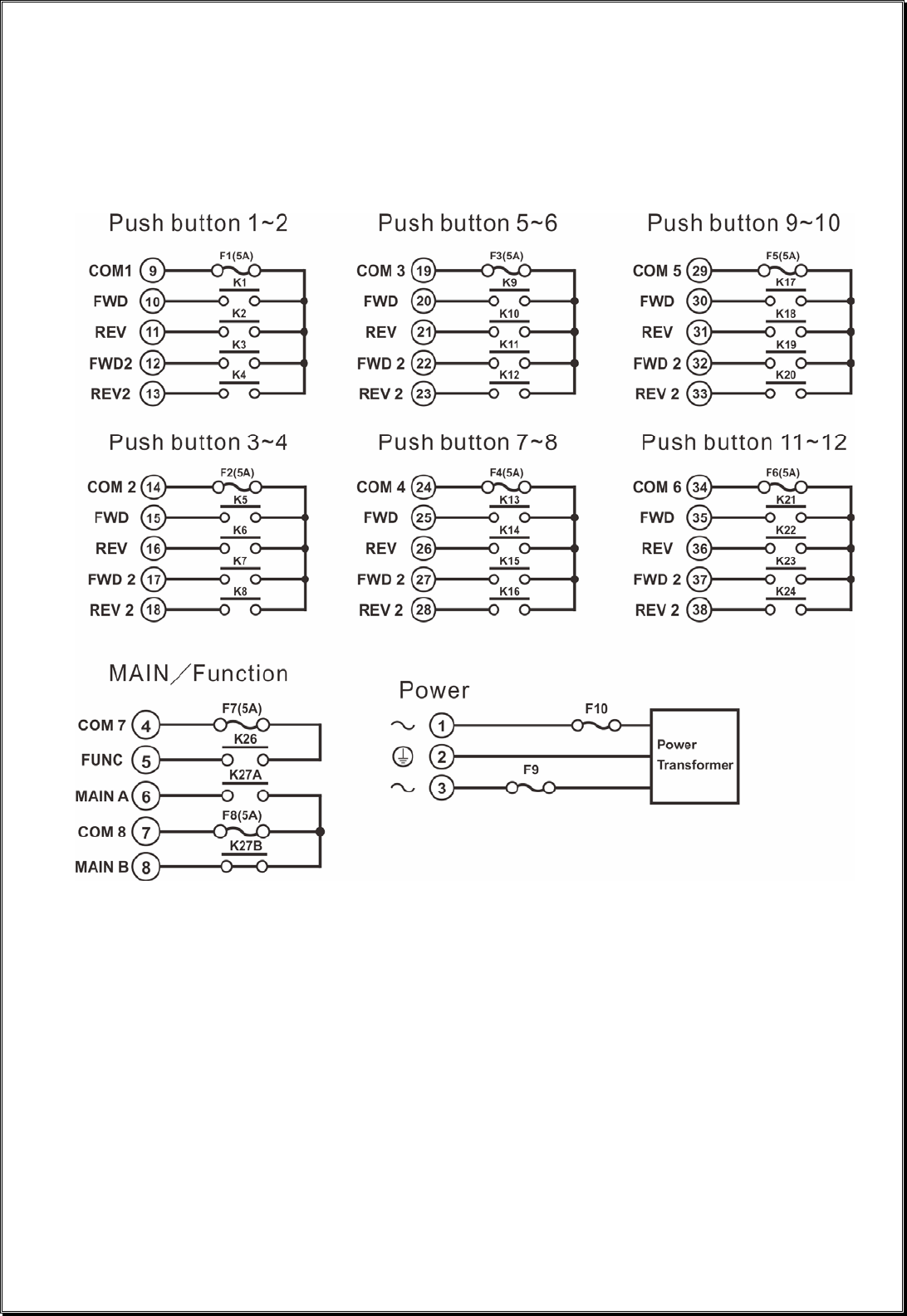
2. Output Relay Configurations
Page 22
F1 R1 F/R2
F1 F2R1 R2
F1 F/R2R1 R1F1 F/R2
R2F2R1F1 R2F2R1F1
a. Output Relay Types
1. Three (3) output relays per motion – shared 2nd speed output relay
Output relays with Forward 1st speed (F1), Reverse 1st speed (R1) and Forward/Reverse 2nd
speed (F/R2). Forward and Reverse 2nd speed (F/R2) shared the
same output relay.
2. Four (4) output relays per motion – separate 1st and 2nd speed output relays
Output relays with Forward 1st speed (F1), Reverse 1st
speed (R1), Forward 2nd speed (F2) and Reverse 2nd
speed (R2). Forward and Reverse 2nd speed with
separate output relays.
b. Output Relay Actions at 2nd Speed
1. 3-output relays configuration with Closed/Closed contact at 2nd speed
At 2nd speed, both 1st speed (F1 or R1) and 2nd speed (F/R2) output relays are closed
(refer to page 26 on how to set to this function).
Forward 1
st speed push button pressed Forward 2nd speed push button pressed
↓ ↓
2. 4-output relays configuration with Opened/Closed contact at 2nd speed
At 2nd speed, only the 2nd speed (F2 or R2) output relay is closed (refer to page 26 on how to
set to this function).
Forward 1
st speed push button pressed Forward 2nd speed push button pressed
↓ ↓
3. 4-output relays configuration with Closed/Closed contact at
Page 23
ON
OFF
F1 R1 F2 R2R2F2R1F1
Fwd Rev Slow FastFwd Rev Slow Fast
Fwd Rev Slow Fast Fwd Rev Slow Fast
2nd speed
At 2nd speed, both 1st speed (F1 or R1) and 2nd speed (F2 or R2) output relays are closed (refer
to page 26 on how to set to this function).
Forward 1
st speed push button pressed Forward 2nd speed push button pressed
↓ ↓
4. 4-output relays configuration with Forward and Fast output relays
engaged at 2nd speed.
Forward 1
st speed push button pressed Forward 2nd speed push button pressed
↓ ↓
5. 4-output relays configuration with Forward, Slow, and Fast output relays
engaged at 2nd speed.
Forward 1
st speed push button pressed Forward 2nd speed push button pressed
↓ ↓
c. ON/OFF Push Button Function
The user can set any of the two adjacent push buttons on the transmitter to behave like a
mechanical ON & OFF rocker switch (refer to page 26 on how to set to this function). When
“On” output relay is closed (“On” push button pressed), the “Off” output relay will open
automatically, or vise versa.
Page 24
OFF
3rd
SPEED
d. Magnet ON/OFF Push Button Function
The user can set any of the two adjacent push buttons on the transmitter to control a magnet. To
activate the magnet just press the push button with the Magnet symbol. To deactivate the magnet,
for safety purpose, you must first press and hold the Magnet push button and then press the OFF
push button. Press the OFF push button by itself can not deactivate the magnet (refer to page 26
on how to set to this function).
e. Brake Function
When the transmitter push button is released from 2nd speed up to 1st speed, both 1st and 2nd
speed output relays will open for up to 1.0 second and then with 1st speed output relay closed
thereafter (refer to page 26 on how to set to this function).
f. External Warning Function
The user can install an external warning device (rotating lights, horn, etc…) to a special
“Function output relay” located inside the receiver. The user can choose which push button pairs
or crane motions he desired to have external warnings when push button is pressed (refer to
page 26 on how to set to this function).
g. Momentary Contact
When push button is released the output relay corresponds to that push button will open (refer
to page 27 on how to set to this function). This type of contact is usually applies to external
application such as horns or buzzers.
h. Toggled Contact
When push button is released the output relay corresponds to that push button will remained
closed (maintained contact) until next time the user presses the same push button again (refer
to page 27 on how to set to this function). This type of contact is usually applies to external
application such as lights.
i. 3rd Speed Push Button Function
This function allows the crane to travel an additional step beyond 2nd speed. For example, if the
operator is pressing the “UP” push button down to 2nd speed, pressing the 3rd speed push button
(with “UP” push button still hold at 2nd speed) will toggle between 2nd speed and 3rd speed (refer
to page 27 on how to set to this function).
Page 25
Aux
STOP
41 32 65 87
4132 65 87
42317856
41 2 3 65 78
j. Auxiliary STOP Push Button Function (JP3 must be inserted)
The auxiliary STOP function acts as a 2nd emergency stop button. Other than by emergency
stop button and transmitter power key switch, the receiver MAIN is also deactivated when
this auxiliary stop push button is pressed (refer to page 27 on how to set to this function).
k. Pitch & Catch Function
This function allows two operators controlling one crane from opposite ends of a cross or long
travel (refer to page 27 on how to set to this function). When set to “Pitch & Catch” make sure
the 2nd transmitter is set to the next upper channel (channel X*+1). For example, if the system is
preset at “Ch.01” then the channel of the 2nd transmitter should be set to “Ch.02”. Furthermore,
the dip-switch position #7 and #8 on the receiving module should be set to “10”, this will allow
the receiver to scan only Ch.01 and Ch.02 (please refer to the illustration below). On the other
hand, since there are only 62 available channels on the Flex system, the system preset at channel
62 is ineffective because the 2nd transmitter can not be set to Ch.63. If your system is preset at
Ch.62 do make sure to change it to another channel.
3. Receiver Auto-Scanning Settings
Receiver Channel Dip-switch
↓
(1) → Scanning all 62 channels (manufacture preset)
For standard operation
(2) → Single fixed channel (channel X*)
Auto scanning function disabled
(3) → Scanning 2 channels only (channel X*, channel X*+1)
For Pitch & Catch, Tandem, and Random Access operation with 2 receivers
(4) → Scanning 3 channels only (channel X*, channel X*+1, channel X*+2)
For Random Access operation with 3 receivers
* Channel X → Channel set on the receiving module
Example: If the first 6 dip-switch positions on the receiving module is set to Ch.01 (“000000” or
“000001”), when set to 2-channel scanning (type-3 above), then the receiver will only scan
Ch.01 and Ch.02.
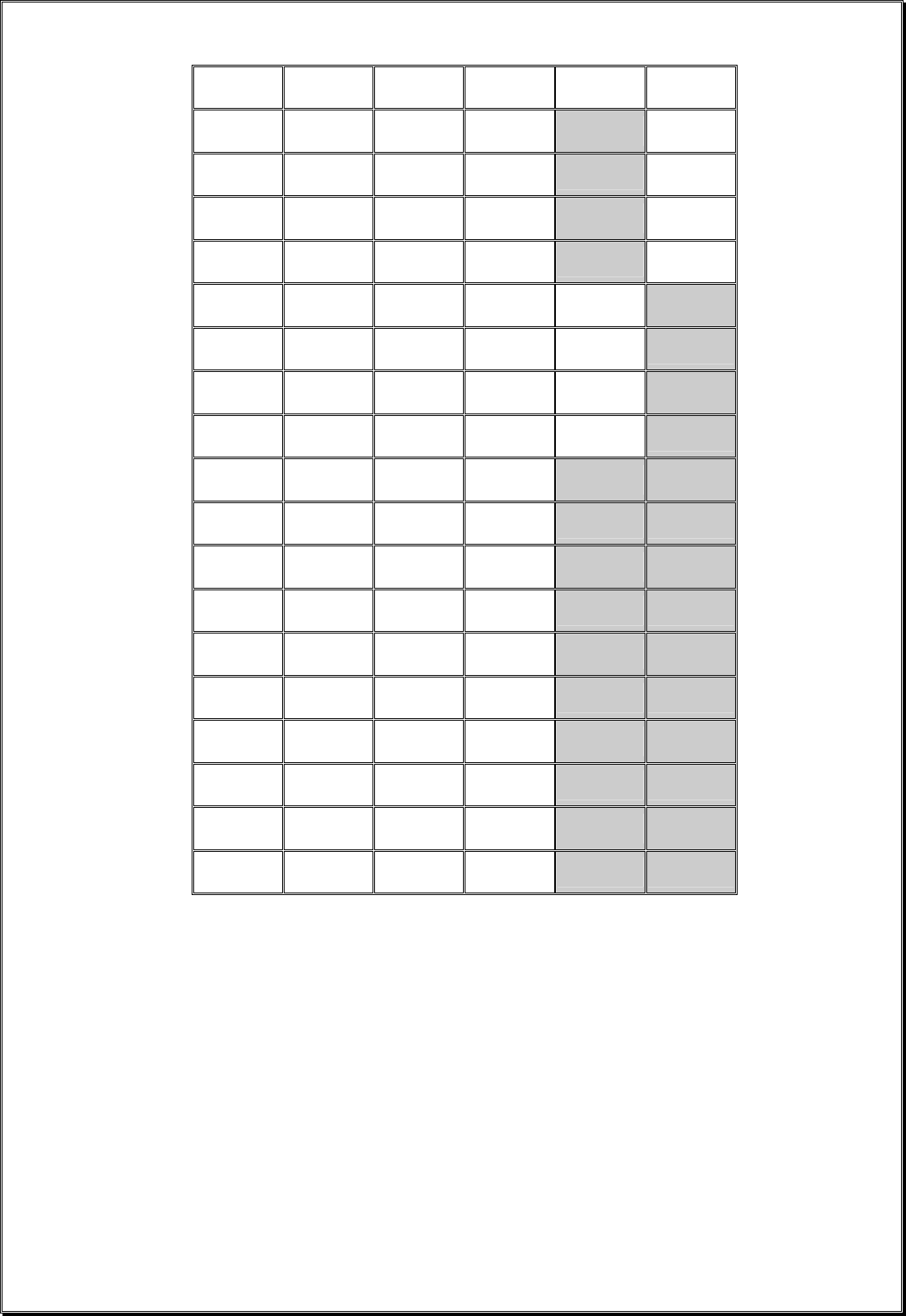
Page 26
RELAY FUNCTIONS
1 324 756 8
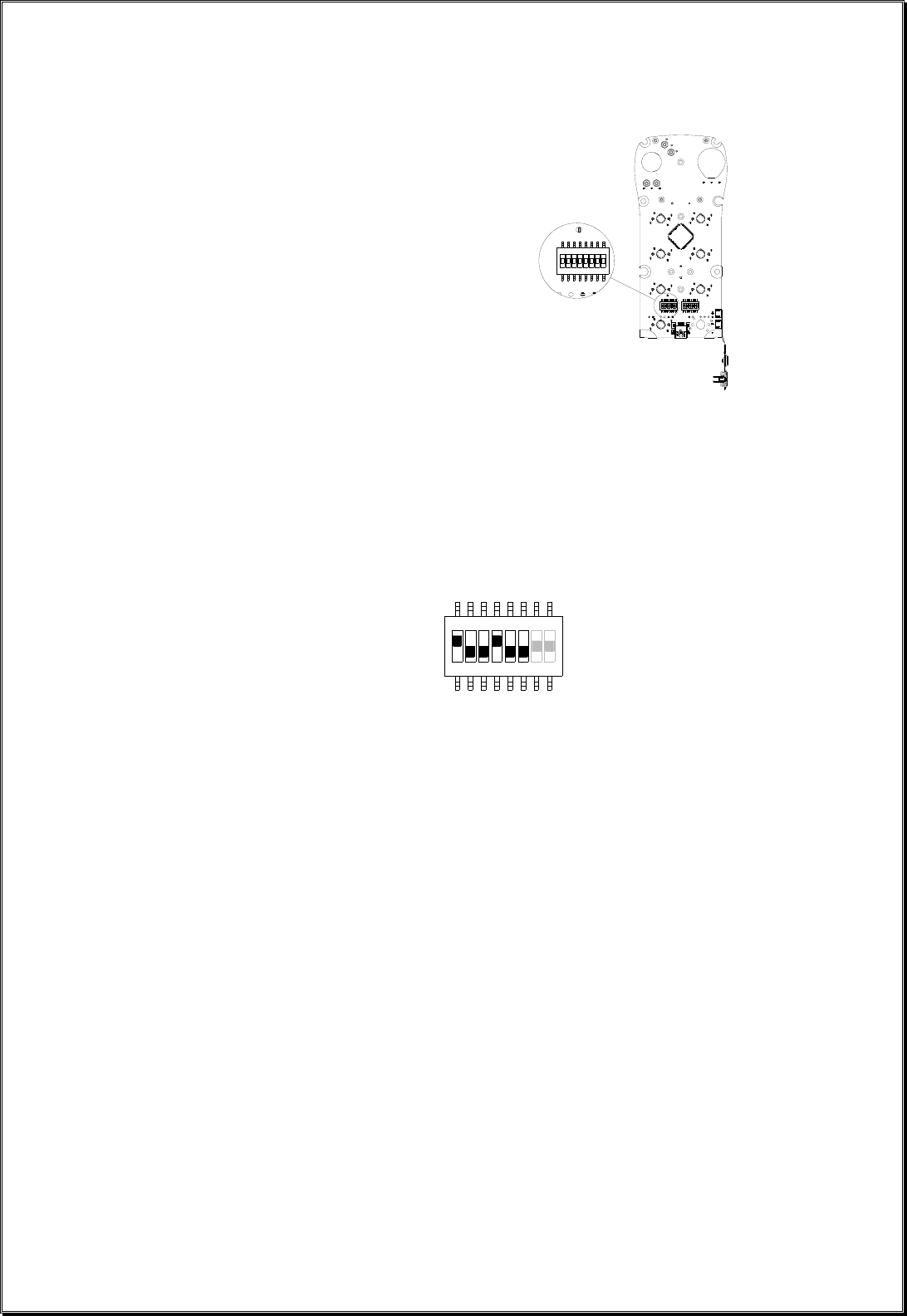
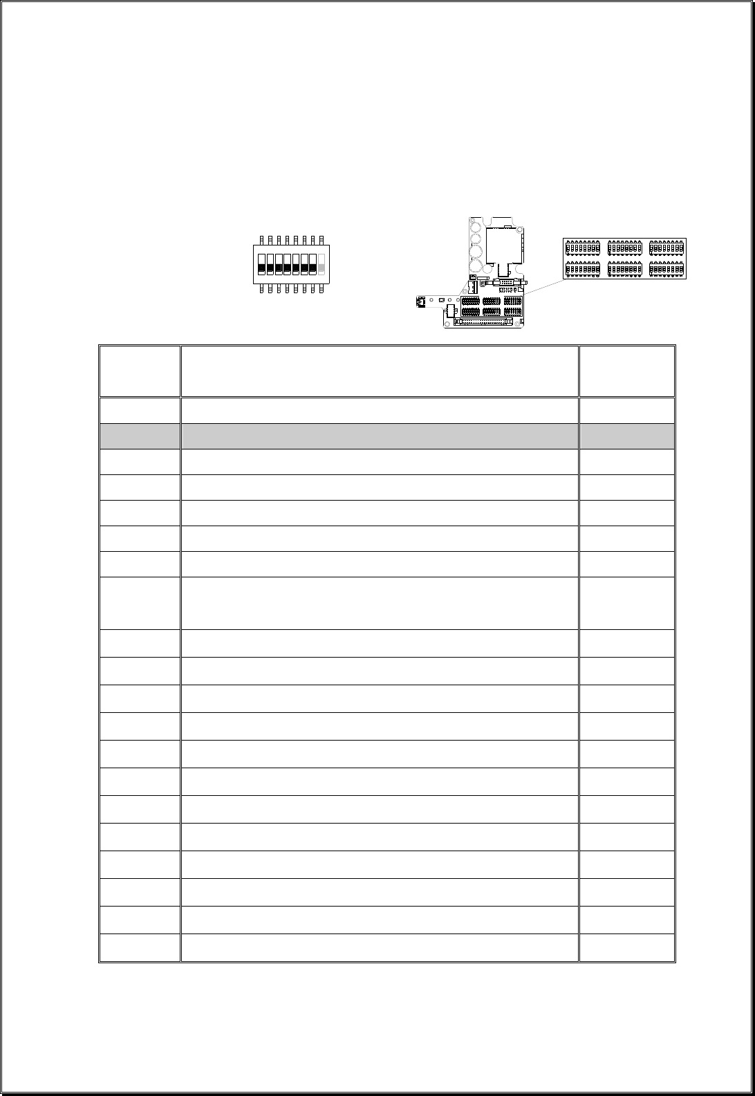
4. Dip-Switch Settings
a. Interlocked Functions
Interlocked means the two adjacent push buttons can not be activated simultaneously at the same
time as it will cancel each other out. Interlocked settings are usually applied to crane’s forward and
reverse motions. Each dip-switch on the decoder module corresponds to one (1) motion or two (2)
adjacent push buttons (refer to Fig. 14 & 15 below). Only the first 7 dip-switch positions are used
(counting from left to right), the 8th dip-switch position (far right) is not used.
(Fig. 14)
(Fig. 15)
▇ Manufacture preset
Dip
Settings Function Descriptions # of Relays
Used
0000000 Normal (single speed only, F2 & R2 relays not used) 2
0000001 Closed/Closed Relay Action at 2nd Speed (separate 2nd speed relay) 4
0000010 Closed/Closed Relay Action at 2nd Speed (shared 2nd speed relay) 3
0000011 Opened/Closed Relay Action at 2nd Speed (separate 2nd speed relay) 4
0000100 Forward and Fast output relays engaged at 2nd speed 4
0000101 Forward, Slow, and Fast output relays engaged at 2nd speed 4
0000110 On (right button) & Off (left button) 2
0001001
On + Start / Off + Start -- Prior to pressing the button you must
first rotate and hold the power key switch at START position
to activate On or Off relays.
2
0000111 Safety Magnet On & Off 2
0001010 FWD/REV toggled (latching) 2
0010000 Normal + External Warning* 2
0010001 Closed/Closed Relay Action + External Warning* 4
0010010 Closed / Closed Relay Action + External Warning* 3
0010011 Opened/Closed Relay Action + External Warning* 4
0100001 Closed/Closed + Brake 4
0100010 Closed/Closed Relay Action + Brake 3
0100011 Opened/Closed Relay Action + Brake 4
0110001 Closed/Closed Relay Action + Brake + External Warning* 4
0110010 Closed/Closed Relay Action + Brake + External Warning* 3
0110011 Opened/Closed Relay Action + Brake + External Warning* 4
* External warning function requires installing an external warning device such as horn and rotating lights to the function relay
output.

Page 27
b. Non-Interlocked Functions
Contrary to interlocked settings, non-interlocked settings allow the two adjacent push buttons be
used simultaneously at the same time. Non-interlocked settings are usually applied to crane’s
auxiliary functions such as lights, horn, 3rd speed, auxiliary stop and Pitch & Catch. Each
dip-switch on the decoder module corresponds to one (1) motion or two (2) adjacent push
buttons (left & right push buttons).
Function
Code
Dip
Position
Setting
#1
Dip Position Setting
#2 ~ #4 (left button)
&
#5 ~ #7 (right button)
Function Description
A 1 000 Normal (momentary) contact
B 1 001 Toggled (latching) contact
C 1 010 Acceleration (3rd speed)
D 1 100
Normal + Start function. For added safety,
you must first rotate and hold the power key
switch at “START” position and then press
the intended push button at the same
time to activate the output relay.
E 1 110 Pitch & Catch
F 1 111 Auxiliary Stop
Example #1: Left button (set to function code A) / right button (set to function code A) → 1 000 000
Example #2: Left button (set to function code B) / right button (set to function code B) → 1 001 001
Example #3: Left button (set to function code A) / right button (set to function code C) → 1 000 010
Example #4: Left button (set to function code F) / right button (set to function code A) → 1 111 000
! When set to Pitch & Catch function make sure the 2nd transmitter is set to the next upper channel. For example, if the
system is preset at Ch.01 then the 2nd transmitter should be set to Ch.02. Furthermore, you must also set the dip-switch on
the receiving module (position #7 & #8) to “10” position (2-channel scanning), please refer to page 25.
!! When set to “Auxiliary Stop” do make sure that JP3 is inserted (refer to jumper settings next page).
Page 28
JP1
JP2
JP3
JP4
JP5
JP6
JP7
5. Jumper Settings
Jumper settings are applied to functions such as Start command, transmitter push button layout,
system information (serial number/ID code) programming, and system testing. The jumpers #3 ~ #7
are located on the decoder module above the six (6) dip-switches (refer to Fig.16 below).
(Fig. 16)
▇ Manufacture preset
Jumper Settings Function
JP3
(Blank)
After transmitter inactivity (MAIN deactivated), press
any push button on the transmitter to reactivate the receiver MAIN.
JP3
(Inserted)
After transmitter inactivity (MAIN deactivated), rotate
the transmitter power key-switch to “START” position to reactivate the
receiver MAIN.
JP4
(Blank)
JP5
(Blank) Standard right-to-left push button configuration for all models.
JP4
(Inserted)
JP5
(Blank) In-line push button configuration (top to bottom) for FLEX 8ES/EX.
JP4
(Blank)
JP5
(Inserted) In-line push button configuration (top to bottom) for FLEX 12ES/EX.
JP4
(Inserted)
JP5
(Inserted) In-line push button configuration (top to bottom) for FLEX 4ES/EX.
JP6
(Blank)
Program system serial number/ID code and channel from decoder module
to I-CHIP.
JP6
(Inserted)
Program system serial number/ID code and channel from I-CHIP
to decoder module.
JP7
(Inserted) For system test only, receiver MAIN disabled.
Page 29
COM 1234
6. I-Chip Programming Port
(Fig. 17)
I-CHIP programming port located on the decoder module (refer to Fig. 17 above) inside the receiver
is designed for the purpose of transferring system serial number/ID code either from I-CHIP to
receiver or from receiver to I-CHIP. If you wish to transfer system information from receiver to
I-CHIP, just insert the I-CHIP onto the programming port (JP6 jumper not inserted), wait until the
Status LED on the decoder module turned constant green (within 2 seconds), and then take the
I-CHIP out of the programming port (programming completed). At this time the I-CHIP should also
possess the same serial number/ID code as the receiver. If the Status LED on the decoder module
displayed a constant red light after inserting the I-CHIP (programming failed), then you must
reinsert the I-CHIP one more time. On the other hand, if you wish to transfer system information
from I-CHIP to receiver, then you must first insert JP6 jumper prior to inserting the I-CHIP, then
wait for the green light to appear on the Status LED. At this time the receiver should also possess
the same system information as the I-CHIP. Please note that the receiver unit must be powered in
order to proceed with the programming.
7. Voltage Settings
Prior to installation always check the voltage setting is correct for your application (refer to Fig. 18
below).
Position 1 → AC110–120V~ 50/60Hz
Position 2 → AC220–240V~ 50/60Hz
Position 3 → NA
Position 4 → NA
(Fig. 18)
F9 and F10 power fuse ratings:
FUSE # AC110–120V~ 50/60Hz AC220–240V~ 50/60Hz
F9 1.0A (red) 1.0A (red)
F10 1.0A (red) 1.0A (red)
* Output relay fuse → 5.0A (clear)

Page 30
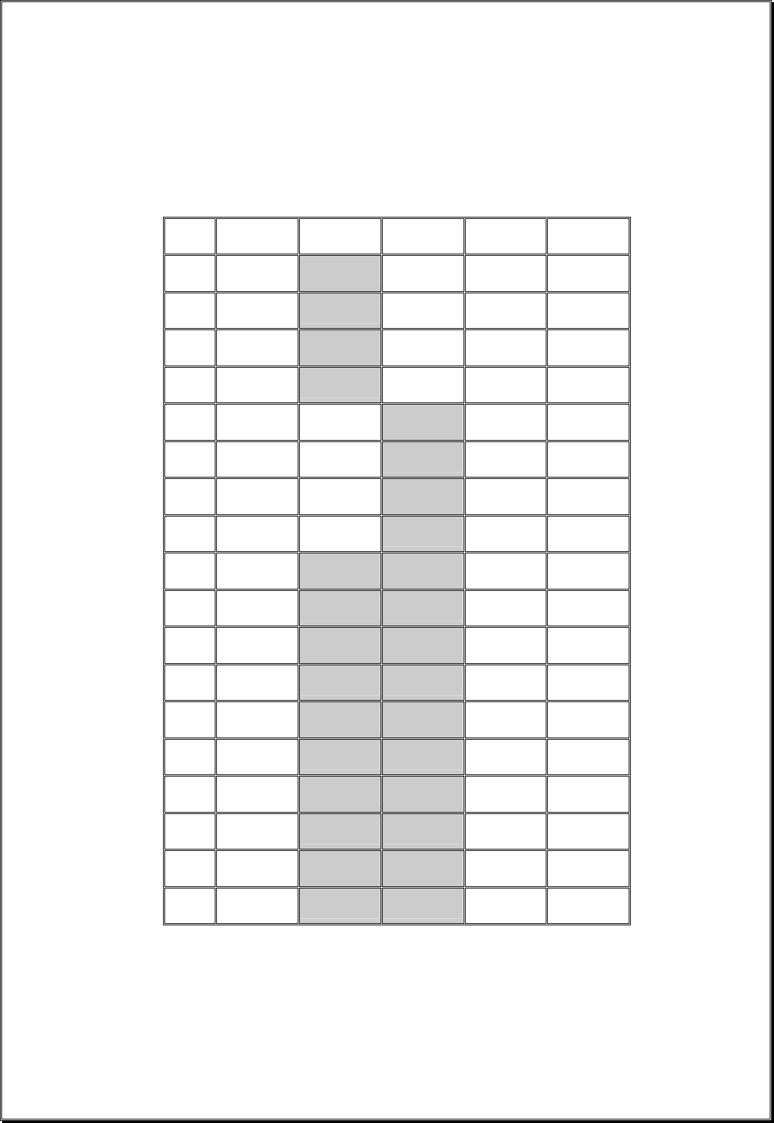
5. System Channels Table
Channel Frequency Dip-switch
Setting Channel Frequency Dip-switch
Setting
01 433.000MHZ 000000 32 433.775MHZ 100000
01 433.000MHZ 000001 33 433.800MHZ 100001
02 433.025MHZ 000010 34 433.825MHZ 100010
03 433.050MHZ 000011 35 433.850MHZ 100011
04 433.075MHZ 000100 36 433.875MHZ 100100
05 433.100MHZ 000101 37 433.900MHZ 100101
06 433.125MHZ 000110 38 433.925MHZ 100110
07 433.150MHZ 000111 39 433.950MHZ 100111
08 433.175MHZ 001000 40 433.975MHZ 101000
09 433.200MHZ 001001 41 434.000MHZ 101001
10 433.225MHZ 001010 42 434.025MHZ 101010
11 433.250MHZ 001011 43 434.050MHZ 101011
12 433.275MHZ 001100 44 434.075MHZ 101100
13 433.300MHZ 001101 45 434.100MHZ 101101
14 433.325MHZ 001110 46 434.125MHZ 101110
15 433.350MHZ 001111 47 434.150MHZ 101111
16 433.375MHZ 010000 48 434.175MHZ 110000
17 433.400MHZ 010001 49 434.200MHZ 110001
18 433.425MHZ 010010 50 434.225MHZ 110010
19 433.450MHZ 010011 51 434.250MHZ 110011
20 433.475MHZ 010100 52 434.275MHZ 110100
21 433.500MHZ 010101 53 434.300MHZ 110101
22 433.525MHZ 010110 54 434.325MHZ 110110
23 433.550MHZ 010111 55 434.350MHZ 110111
24 433.575MHZ 011000 56 434.375MHZ 111000
25 433.600MHZ 011001 57 434.400MHZ 111001
26 433.625MHZ 011010 58 434.425MHZ 111010
27 433.650MHZ 011011 59 434.450MHZ 111011
28 433.675MHZ 011100 60 434.475MHZ 111100
29 433.700MHZ 011101 61 434.500MHZ 111101
30 433.725MHZ 011110 62 434.525MHZ 111110
31 433.750MHZ 011111
Page 31
6. Receiver Installation
A. OUTPUT RELAY CONTACT DIAGRAM
* For 3-relay (shared 2nd speed) and 4-relay (separate 2nd speed) configuration please refer to page 22~26.
* For 4-relay closed/closed and 4-relay opened/closed relay configuration please refer to page 22~26.
* For different voltage settings please refer to page 29.
* For F9 and F10 power fuse ratings please refer to page 29.
Page 32
B. PRE-INSTALLATION PRECAUTIONS
1. Make sure the transmitter and receiver are with identical serial number/ID code and channel.
2. Make sure the receiver is not set to the same channel as any other systems in use in the
surrounding area.
3. Make sure that the crane or equipment is working properly prior to installation.
4. Make sure the power source to the receiver is set correctly.
5. Switch off the main power source to the crane or equipment prior to installation.
C. STEP-BY-STEP INSTALLATION
(Fig. 19)
Page 33
432 mm
Control
Panel
1. For best reception the location of the receiver should be visible to the operator at all time.
2. The location selected should not be exposed to high levels of electric noise. Mounting the receiver
next to an unshielded variable frequency drive may cause minor interference. Always locate the
receiver as far away from variable frequency drive as possible.
3. Ensure the selected location has adequate space to accommodate the receiver
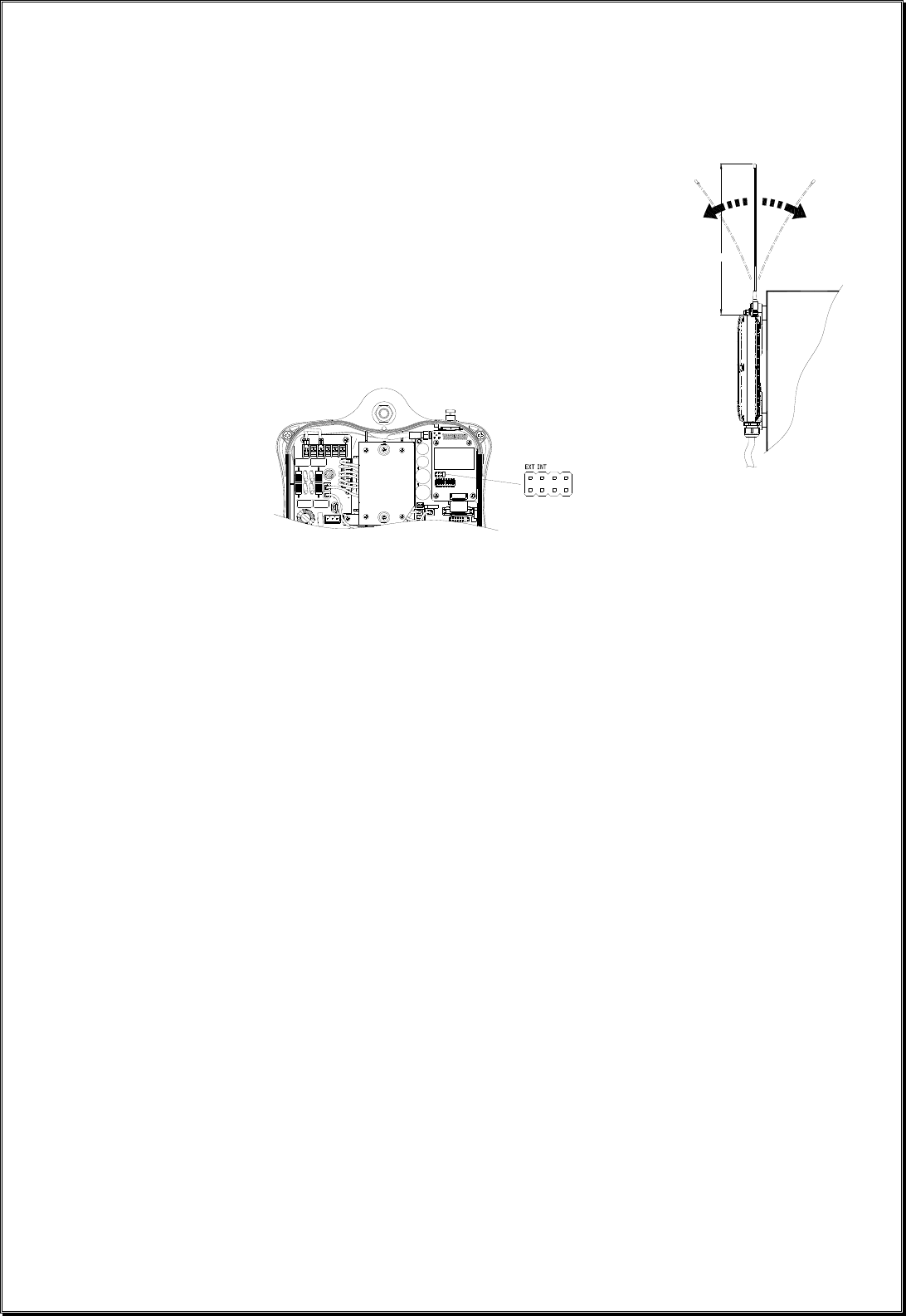
(refer to Fig. 19 on page 32). If an external antenna is used, to avoid the
possibility of antenna damage always locate the receiver where the antenna is
free from any obstacles from all directions (refer to diagram at right).
4. When installing an external antenna you must connect the SMA jack located
inside the receiver and make sure to set the jumper to “EXT” position (refer
to diagram below).
5. For better reception, make sure the receiver is in an upright position.
6. Drill two holes (10mm in diameter) on the control panel or location where the receiver is to be installed
(refer to Fig. 19 on page 32).
7. Make sure the two bolts are tightened after installation.
8. For system wiring please refer to page 31.
D. SYSTEM TESTING
1. Turn on the power source to the receiver and test the MAIN relay output by pressing the red emergency
stop button and observe that it properly opens and closes the mainline disconnect contactor.
2. Test the operation of each function to ensure it corresponds to the transmitter direction labels or the
pendent it is replacing.
3. Test the limit switches (if any) to see if they are working properly.
4. If your new remote control is replacing an existing pendant, make sure it is completely disconnected
and placed in a safe location to prevent unwanted control command.
Page 34
7. Operating Procedure
A. TRANSMITTER OPERATION
1. General Operating Procedure
a. Reset the red emergency stop button located on the top left hand side of the transmitter handset
by rotating it either clockwise or counter clockwise, the red button will pop up.
b. Turn on the transmitter power by inserting the black-colored key into the power key slot located
on the top right hand side of the transmitter handset and rotate it clockwise to “On” position.
c. After turning the transmitter power on, check the Status LED on the transmitter handset for any
sign of system irregularities (refer to “Status Light Indicators & Warnings” on page 37). If the
system is normal the Status LED will light up green for two (2) seconds.
d. If there are no signs of any system irregularities, then rotate the power key-switch further to
START position for up to 1.0 second to activate all transmitter push button functions and as well as
the receiver MAIN. Then press any push button on the transmitter to begin operation. Pressing any
push button prior to initiating the START command will result in no signal transmitted (blinking
orange light).
Page 35
AB
3rd
SPEED
e. In case of an emergency, press down the red emergency stop button will immediately disconnect
the receiver MAIN and as well as the transmitter power. To resume operation, rotate the red button
clockwise or counter-clockwise, it will pop up. Then rotate the power key-switch to START
position for up to 1.0 second to activate all transmitter push button functions and the receiver
MAIN. Please note that every time when you turn the transmitter power off and back on again or
after resetting the emergency stop button, all push button functions will be locked to avoid any
unintentional controls. For safety, initiating the START command after turning on the transmitter
power or after resetting the emergency stop button is strictly required. The receiver MAIN will
also be disconnected temporarily when the receiver encounters strong radio interference or when
the operator is controlling the crane or equipment beyond the transmitting range.
f. Turn off the transmitter power by rotating the power key counter-clockwise to “Off” position; it
will disconnect the transmitter power and the receiver MAIN altogether. Turn it further
counter-clockwise to release the key.
WARNING
Keep away interference source to make sure performance integrate..
2. A/B Selector Push Button Operating Procedure
Pressing the “Select A/B” push button will toggle between output relay A, B, A+B respectively. There
are 4 different types of Select A/B sequence available, please refer to page 11~13 for instructions on
how to set Select A/B functions.
3. 3rd Speed Push Button Operating Procedure
When a push button is hold at 2nd speed, pressing the 3rd Speed push button one time will activate the 3rd
speed output relay (toggled). If the operator wants 2nd speed again, just press the 3rd Speed push button
one more time.
Page 36
O
N
O
F
F
C
A
T
C
H
CATCH
CATCH
PITCH
PITCH
1
2
4. Pitch & Catch Operating Procedure
To release control of the crane, press the “Pitch” push button. To take over control of the crane, rotate the
power key switch to “Catch” position for up to 2 seconds. The 2nd operator “can not” take control of the
crane unless the 1st operator presses the “Pitch” push button (2.0 seconds). If the operator unintentionally
presses the “Pitch” push button during operation, just rotate the power key to “Catch” position for up to
2 seconds to regain control again.
→ →
5. Automatic Channel Scanning Operating Procedure
After changing transmitter channel (refer to page 9), turn on the transmitter power and rotate the power
key switch to “Start” position and hold it there for up to 1.0 minute. Within this 1-minute period the
receiver will search (channel 01 ~ channel 62) and lock onto the newly selected transmitter channel
automatically. Please note that in order for the receiver to switch to auto-scanning mode, prior to
changing the transmitter channel, you must first deactivate the receiver MAIN by shutting off the
transmitter power or press down the emergency stop button. Please refer to page 25 if you do not want
the receiver to auto-scan all 62 channels.
Change Transmitter Channel →
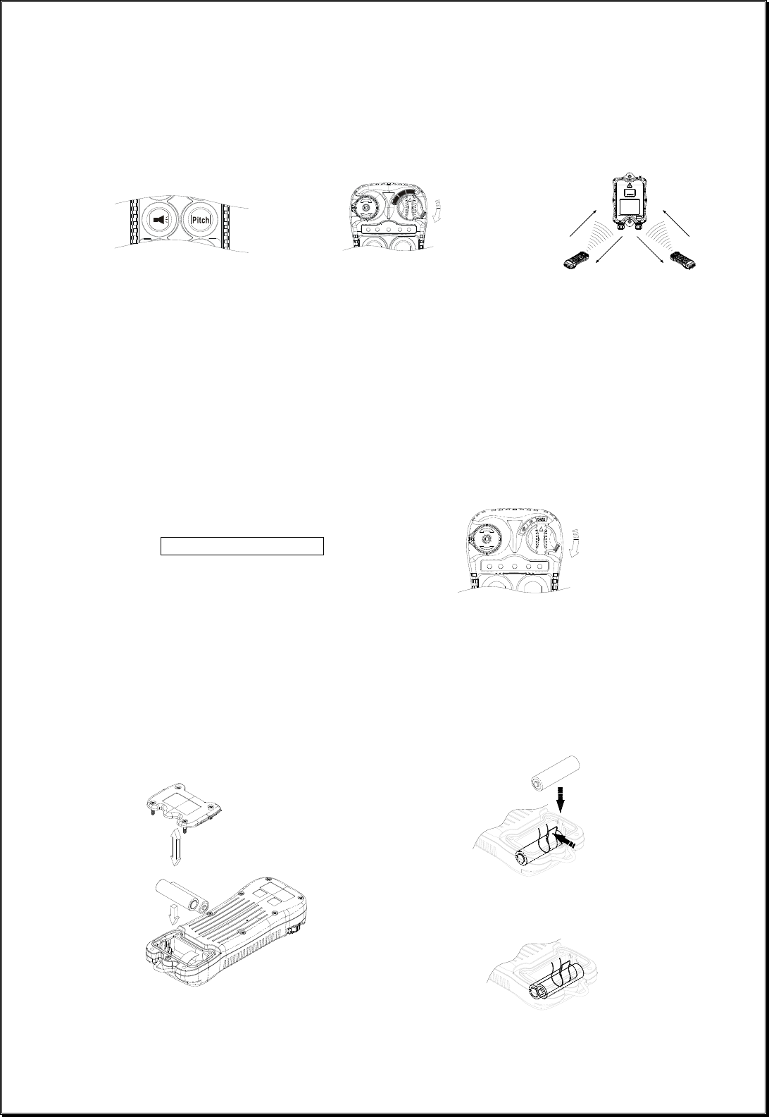
6. Changing Transmitter Batteries
Changing transmitter batteries by unscrewing the battery cover located on the backside of the transmitter
(refer to Fig. 20 below). During battery installations make sure that the blue ribbon is centered between
the two batteries. After changing the batteries also make sure that all screws are tightened to avoid water,
moisture, dirt, grease, or other liquid penetration.
(Fig. 20)
↓

Page 37
B. STATUS LIGHT INDICATORS & WARNINGS
1. Transmitter STATUS Light Indication
Type Display Type Indication
Voltage below 1.9V at initial power on,
transmitter power and receiver MAIN shuts off.
1 Constant red
Voltage below 1.8V during operation,
transmitter power and receiver MAIN shuts off.
2 1 red blinks followed by a 2-second
pause
Voltage below 1.85V during operation, warning,
change batteries suggested.
3 2 red blinks followed by a 2-second
pause
The pushbutton is defective after turning on the
transmitter power.
4 No light displayed
When defective push button condition occurs
(2 red blinks, type 3 above), find out which push
button is defective by pressing all the push
buttons on the transmitter one at a time. If the
push button is in good working order, the LED
will not light up when pressed. If the push
button is defective the LED will continue to
display 2 red blinks when pressed.
5 3 red blinks followed by a 2-second
pause EEPROM error.
6 4 red blinks followed by a 2-second
pause
Transmitting error, system can not locked on
to the designated channel.
7 Constant green for up to 2 seconds Transmitter power on with no faults detected.
8 Blinking green Transmission in progress.
9 Blinking orange Transmitter push button functions locked.
Page 38
2. Receiver STATUS Light Indication
Type Display Type (Green & Red) Indication
1 Fast green blinks Decoding in process
2 Slow green blinks Decoding on standby
3 Two red blinks Receiver MAIN jammed or defective
4 Fast red blinks Incorrect transmitter serial number/ID code
5 Constant red Receiver under-voltage, LV output relay activated
6 No light displayed Decoding microprocessor is defective
3. Receiver SQ Light Indication
Type Display Type (Red) Indication
1 Fast blinks Transmission received
2 Completely off No transmission
3 Blinks intermittently Other radio interference
4. Receiver POWER Light Indication
Type Display Type (Red) Indication
1 On Power to receiver
2 Off No power to receiver
5. Receiver COM Light Indication
Type Display Type (Red) Indication
1 On Power to relay Board
2 Off No power to relay board

Page 39
C. TROUBLE SHOOTING TIPS
Problems Possible Reasons Suggestions
Transmitter low battery power Check the transmitter battery level.
Emergency stop button
activated prior to startup
Prior to turning on the transmitter power
switch make sure that the red emergency
stop button is elevated.
Transmitter push button
functions locked
Initiate the Start command by rotating
the power key-switch to START position.
Incorrect system RF channel
Check and make sure that the transmitter
handset and receiver unit both have the
same channel.
Incorrect system serial
number/ID code
Check and make sure that the transmitter
handset and receiver unit both have the
same serial number/ID code.
No responds when
transmitter push
button is pressed
(Improper startup &
settings)
System out of range Make sure that the operating distance
is within the control range.
Defective transmitting and
receiving module
Check the SQ display on the face of the
receiver unit. If it does not light up
when push button is pressed then either
the transmitting or receiving module is
defective. First replace the transmitting
module. If SQ display still not lid when
push button is pressed then go ahead
and replace the receiving module.
No responds when
transmitter push
button is pressed
(Damaged hardware)
Defective encoder
board or decoder module
If still no responds, then replace the
transmitter encoder board. If still
doesn’t work then the decoder module
is defective.
Incorrect input voltage Make sure the source voltage is set
correctly.
Blown fuse Check for any blown fuse.
No AC power to
the receiver
Incorrect wiring Check input voltage connection.
Outputs do not
correspond to
transmitter
Incorrect output connection
Check the system wiring again. Please
refer to the output contact diagram inside
this manual or on the receiver cover.

Page 40
8. System Specifications
Frequency Range : 433.000 ~ 434.525 MHz
Number of Channels : 62 channels
Channel Spacing : 25 KHz
Modulation : Digital Frequency Modulation based on
Manchester Code, 20bit address, 32bit CRC
Parity Check and Hamming Code.
Encoder & Decoder : Microprocessor-controlled
Transmitting Range : 100 Meters / 300 Feet
Hamming Distance : 6
Frequency Control : Synthesized PLL (Phase Lock Loop)
Receiver Type : Frequency Auto Scanning
Receiver Sensitivity : -116dBm
Spurious Emission : -50dB
Antenna Impedance : 50 ohms
Responding Time : 40 Milliseconds (average)
Transmitting Power : 1.0mW
Enclosure Type : NEMA-4X
Enclosure Rating : IP-66
Output Contact Rating : 250V @ 8 Amps
Transmitter Operating Voltage : DC 3.0V
Receiver Power Consumption : 22.0 VA
Operating Temperature : -25 ~ ℃50 / ℃-13 ~ 1℉22 ℉
Transmitter Dimension : 158mm (L) x 69.0mm (W) x 38mm (H) (4ES/EX)
184mm (L) x 69.0mm (W) x 38mm (H) (8ES/EX)
230mm (L) x 69.0mm (W) x 38mm (H) (12ES/EX)
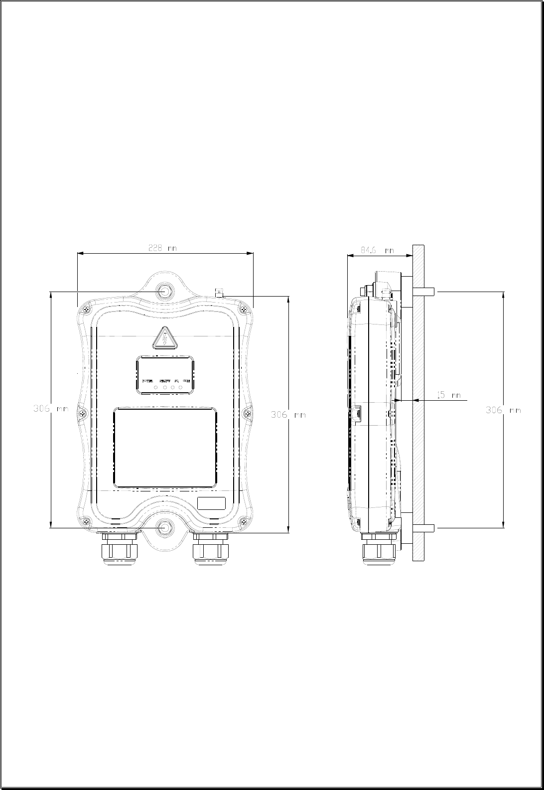
Receiver Dimension : 363mm (L) x 228mm (W) x 70mm (H)
Transmitter Weight : 296g / 10.4oz
Receiver Weight : 2.5kg / 5.5lb
Page 41
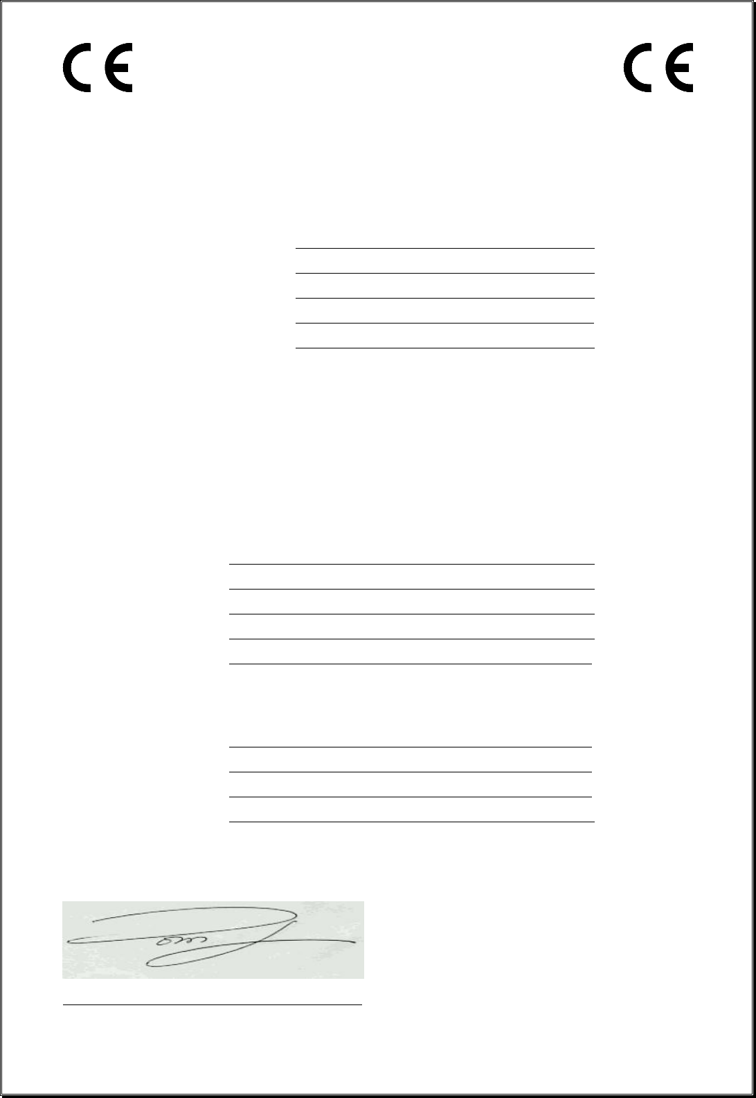
EU Declaration of Conformity
(EMC, R&TTE, SAFETY & MACHINERY)
For the following equipment:
Product : Flex Series Radio Remote Control System
Multiple Listee Model No. : Flex 4ES/EX, 8ES/EX and 12ES/EX
Manufacturer’s Name : Advanced Radiotech Corporation
Manufacturer’s Address : 1F, 288-1, Hsin Ya Road, Chien Chen District,
Kaohsiung City, Taiwan
We herby declare, that all major safety requirements, concerning the CE Mark Directive 2006/42/EC and
Low Voltage Directive 2006/95/EC, Electromagnetic Compatibility Directives 2004/108/EC, R&TTE
Directive 1999/5/EC are fulfilled, as laid out in the guideline set down by the member states of the EEC
Commission.
The standards relevant for the evaluation of the electrical safety requirements are as follow:
EMC : EN 301 489-1 + EN 301 489-3
R&TTE : EN 300 220-2 V2.1.1
SAFETY : EN 60950:2006+A1+A11+A12
MACHINERY: EN 60204-32:2008, EN 13557:2003+A1:2008
EN ISO 13849-1:2008 (PL=d), EN 60529 (IP66)
Test reports issued by:
EMC : SGS UK
R&TTE : SGS UK
SAFETY : SGS UK
MACHINERY: SGS UK
Person responsible for marking this declaration:
Tom Jou / President
Name and signature of authorized person

Page 42
PRODUCT MANUAL SAFETY INFORMATION
Advanced Radiotech Corporation (ARC) offers a broad range of radio remote control product for material
handling applications. This manual has been prepared by ARC to provide information and
recommendations for the installation, use, operation and service of ARC’s material handling products and
systems (ARC Products). Anyone who uses, operates, maintains, services, installs or owns ARC
Products should know, understand, and follow the instructions and safety recommendations in this manual
for ARC Products.
The recommendations in this manual do not take precedence over any of the following requirements
relating to cranes, hoists lifting devices or other material handling equipment which use or include ARC
Products:
Instructions, manuals, and safety warnings of the manufacturers of the equipment where the radio
system is used.
Plant safety rules and procedures of the employers and the owners of facilities where the ARC
Products are being used.
Safety standards and practices for the industries in which ARC Products are used.
This manual does not include or address the specific instructions and safety warnings of these
manufacturers or any of the other requirements listed above. It is the responsibility of the owners, users
and operators of the ARC Products to know, understand and follow all of these requirements. It is the
responsibility of the employer to make its employees aware of all of the above listed requirements and to
make certain that all operators are properly trained. No one should use ARC Products prior to
becoming familiar with and being trained in these requirements and the instructions and safety
recommendations in this manual.
WARRANTY INFORMATION
For information on ARC’s product warranties, please contact ARC representative nearest to you or visit
www.advanced-radiotech.com.
FCC WARNINGS and CAUTIONS
NOTE: This equipment has been tested and found to comply with the limits for a Class B digital device, pursuant to part
15 of the FCC Rules. These limits are designed to provide reasonable protection against harmful interference in a
residential installation. This equipment generates, uses and can radiate radio frequency energy and, if not installed
and used in accordance with the instructions, may cause harmful interference to radio communications. However,
there is no guarantee that interference will not occur in a particular installation. If this equipment does cause harmful
interference to radio or television reception, which can be determined by turning the equipment off and on, the user is
encouraged to try to correct the interference by one or more of the following measures:
— Reorient or relocate the receiving antenna.
— Increase the separation between the equipment and receiver.
— Connect the equipment into an outlet on a circuit different from that to which the receiver is connected.
— Consult the dealer or an experienced radio/TV technician for help.
RADIO FREQUENCY INTERFERENCE STATEMENT
This device complies with Part 15 of the FCC rules. Operation is subject to the following two conditions:
1) this device may not cause harmful interference, and
2) this device must accept any interference received, including interference that may cause undesired
operation.
FCC Caution: Any change or modification not expressly approved by the party responsible for
compliance could void the user’s authority to operate this equipment.