Advanced Radiotech FLEXSERIES Remote Control System User Manual ARC FLEX FCC
Advanced Radiotech Corporation Remote Control System ARC FLEX FCC
Transmitters users manual

FLEX
User’s Manual

1
Table of Contents
Page
1. Introduction 2
2. Radio Controlled Safety 3
3. General System Information
A. Transmitter Handset
1. External Illustration 4
2. Internal Illustration 5
B. Receiver Unit
1. External Illustration 6
2. Internal Illustration 7
4. Function Settings
A. Transmitter Handset
1. System Channel Settings 8
2. Pushbutton Functions with LED Display Settings 9~13
B. Receiver Unit
1. System Channel Settings 13
2. Output Relay Configurations 14~15
3. Dip-switch Settings 16~17
4. Jumpers Settings 18
5. System Channels Table 19
6. Receiver Installation
A. Output Relay Contact Diagrams 20
B. Receiver Mounting
1. Pre-installation Precautions 21
2. Step-by-Step Installation 21~22
3. System Testing 22
7. Operating Procedure
A. Transmitter Operation 23
B. Status Light Indicators & Warnings
1. Transmitter STATUS Light Indication 24
2. Receiver STATUS Light Indication 25
3. Receiver SQ Light Indication 25
4. Receiver Power Light Indication 25
5. Receiver COM Light Indication 25
C. Trouble Shooting Tips 26
8. System Specification 27
9. Spare Parts 28

2
1. Introduction
The ARC FLEX radio remote control systems are designed for control of industrial equipment and
machinery such as overhead traveling cranes, jib cranes, gantry cranes, tower cranes, electric hoists, winches,
monorails, conveyor belts, mining equipment and other material handling equipment where wireless control is
preferred.
Each FLEX system consists of a transmitter handset and receiver unit. Other standard-equipped
accessories include transmitter waist belt, “AA” batteries, compass direction decal sheet and user’s manual.
List of notable features include:
* 62 user-adjustable channels – no more fixed channels and fragile quartz crystals to break.
* Over one million sets of unique ID codes (20-bit) – unlike many other radio control systems on the
market, the FLEX system never repeats ID codes.
* Advanced microprocessor controls with 32-bit CRC and Hamming Codes programming – ultra fast,
safe, precise and error-free encoding and decoding.
* Ultra-durable transmitter push button – good for up to one million press cycles.
* Ultra power-saving transmitter – requires only two “AA” Alkaline or rechargeable batteries
(2000mA or above) for more than 100 hours of continuous operating time between replacements or
recharging.
* Ultra durable nylon and fiberglass composite enclosures – resist breakage from high impacts and
frequent drops; no more fragile casings to replace.
* 100% water and shock resistant
* Adjustable waist belt for easy carry and operation.

3
2. Radio Controlled Safety
Flex radio remote control system should be operated by persons with sufficient amount of knowledge and
skill in crane operation and safety. Persons being trained to operate a radio remote controlled crane should
possess the knowledge of all hazards peculiar to radio remote controlled crane operation, ability to judge
distance and moving objects, equipment capacity and radio remote controlled safety rules. Radio remote
controlled cranes should not be operated by any person with insufficient eyesight, hearing, illness, and under
influence of drugs and medications that may cause loss of crane control.
Below are some general operating safety tips that should be strictly followed when operating a radio
remote controlled crane.
1. Prior to crane operation always check the transmitter handset for any damage that might inhibit
proper crane operation.
2. Always check if the red emergency stop button is working properly prior to crane operation.
3. Check the battery status LED on the transmitter for any signs of low battery power.
4. Check the Status LED on the transmitter for any signs of irregularities. Please refer to the
“Transmitter Status Light Indicators & Warnings” on page 24.
5. The crane limit switches should be checked prior to crane operation or at the beginning of each shift.
When checking limit switches the hoist should be centered over an area free of personnel and
equipment.
6. If power to the crane is removed, the operator should turn off the transmitter power immediately
until the power to the crane is restored.
7. If the crane fails to respond properly to operator ’s command the operator should stop operation, turn
the transmitter power off, and then report the condition to their supervisor.
8. The transmitter power should be turned off after each use. If the transmitter handset is not in use
always turn the power off and stored it in a safe or designated location. Never leave the transmitter
handset unattended in the working area.
9. Even though Flex system is capable of allowing up to four systems with same channel in use
without interfering with one another, it is always a good practice not to use the same RF channel as
any other Flex systems in use within a distance of 200 feet.
10. Never operate a crane or equipment with two identical channel and ID transmitter handsets at the
same time within the same facility.
4
3. General System Information
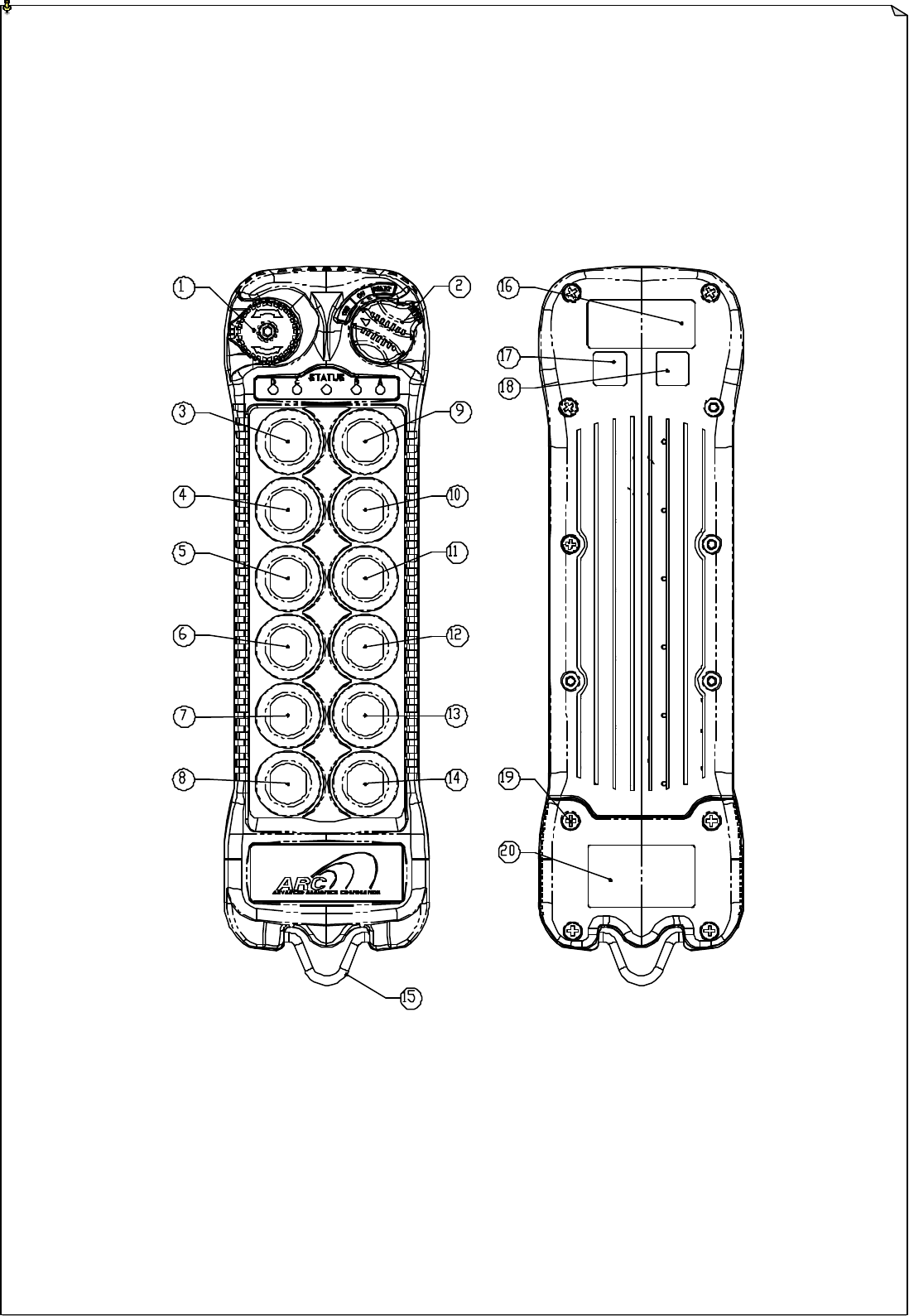
A. TRANSMITTER HANDSET
1. External Illustration
Fig. 01 Fig. 02
1. Emergency Stop Button 8. Push button #12 15. Strap Holder
2. Power Key Switch 9. Push button #1 16. System Information
3. Push button #2 10. Push button #3 17. System Channel
4. Push button #4 11. Push button #5 18. Crane Number
5. Push button #6 12. Push button #7 19. Battery Cover
6. Push button #8 13. Push button #9 20. FCC/CE Information
7. Push button #10 14. Push button #11
5
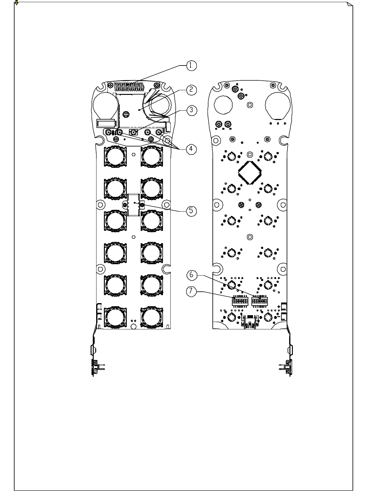
2. Internal Illustration
Fig. 03 Fig. 04
1. Arial Antenna 5 I-CHIP
2. Transmitting Board 6 Function Dip-Switch
3. Status LED Display 7 Channel Dip-Switch
4. Function LED Display
6
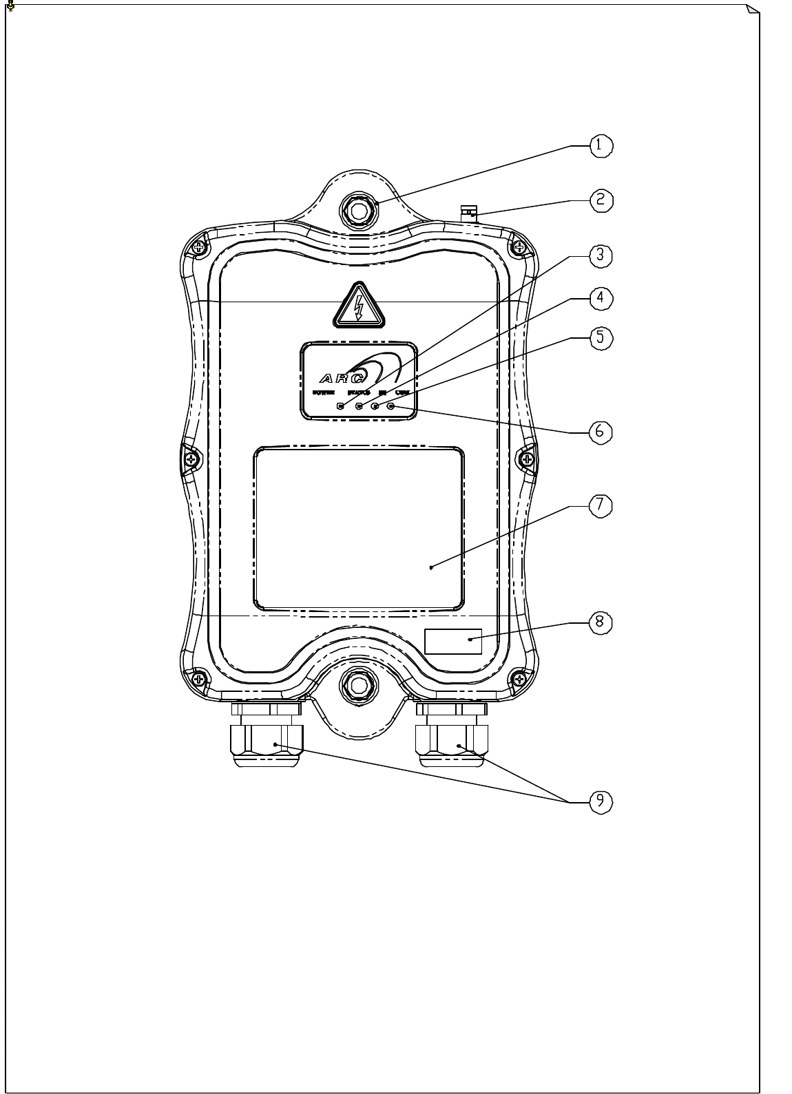
B. RECEIVER UNIT
1. External Illustration
Fig. 05
1. Shock Absorber 6. COM LED Display
2. External Antenna BNC Jack 7. Output Contact Diagram
3. Power LED Display 8. System Information
4. Status LED Display 9. Cable Gland/ Cord Grip
5. SQ LED Display
7
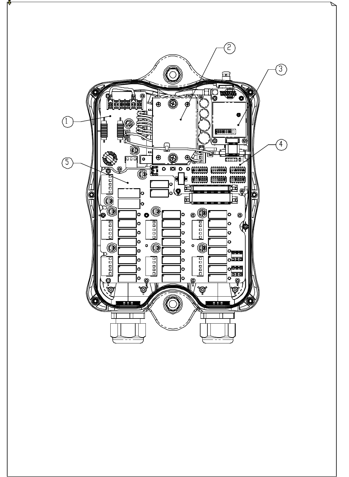
2. Internal Illustration
Fig. 06
1. AC Line Filter 4. Decoder Board
2. Power Transformer 5. Relay Board
3. Receiving Board
8
71 42 3 5 6 8
4. Function Settings
A. TRANSMITTER HANDSET
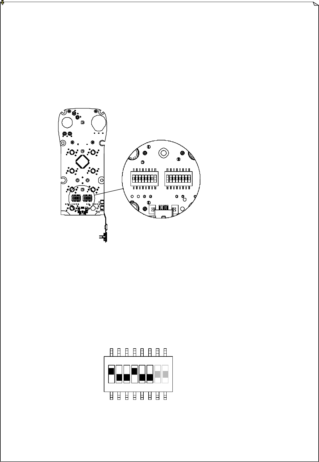
1. System Channel Settings
Fig. 07
Set the transmitter channel simply by adjusting the channel dip-switch located on the backside of the
transmitter encoder board. The system channel table located on page 19 will tell you which dip setting
correspond to which channel. Do make sure that when you change the channel of the transmitter you
must also change the channel of the receiver as well. The channel on both transmitter and receiver must
be identical in order for the system to work.
Example:
Top slot ? “1”
(Fig. 08) Bottom slot ? “0”
The above dip setting would be “100100”, which corresponds to “channel 36” in the system
channels table on page 19.
1 2 3 4 5 6 7 8 1 2 3 4 5 6 7 8
CHANNEL FUNCTION
9
1 2 3 4 5 6 7 8 1 2 3 4 5 6 7 8
CHANNEL FUNCTION
2. Push Button Functions with LED Display Settings
A. 1-Stage Toggle Switch with LED Display
Below are settings for toggle or latching functions. You can set each and every push button
on the transmitter with toggle d (latching) relay contact. The number (1 to 4) below the
push button tells you which LED on the transmitter will light up when the push button is
pressed.
Fig. 08
DIP PB1
PB2
PB3 PB4
PB5
PB6 PB7 PB8
PB9
PB10
PB11
PB12
1 00000001
4
2 00000010 3 4
3 00000011 2 3 4
4 00000100 1 2 3 4
5 00000101 4
6 00000110 3 4
7 00000111 2 3 4
8 00001000 1 2 3 4
9 00001001 4
10
00001010 3 4
11
00001011 2 3 4
12
00001100 1 2 3 4
13
00001101 4
14
00001110 3 4
15
00001111 2 3 4
16
00010000 1 2 3 4
1 ? LED #1 will light up when the push button is pressed
2 ? LED #2 will light up when the push button is pressed
3 ? LED #3 will light up when the push button is pressed
4 ? LED #4 will light up when the push button is pressed

10
B. 3-Stage Selector Switch
DIP PB1
PB2
PB3 PB4
PB5
PB6 PB7 PB8
PB9
PB10
PB11
PB12
17
00010001
A/1&2
18
00010010 B/1&2
19
00010011 C/1&2
20
00010100 D/1&2
21
00010101 A/3&4
22
00010110 B/3&4
23
00010111 C/3&4
24
00011000 D/3&4
25
00011001 A/1&2
A/3&4
26
00011010 A/1&2
B/3&4
27
00011011 A/1&2
C/3&4
28
00011100 A/1&2
D/3&4
29
00011101 B/1&2
B/3&4
30
00011110 B/1&2
C/3&4
31
00011111 B/1&2
D/3&4
32
00100000 C/1&2
C/3&4
33
00100001 C/1&2
D/3&4
34
00100010
D/1&2
D/3&4
35
00100011
A/1&2
36
00100100 B/1&2
37
00100101 C/1&2
38
00100110
D
/1&2
39
00100111 A/3&4
40
00101000 B/3&4
41
00101001 C/3&4
42
00101010 D/3&4
A ? Select A/B
B ? Select 0/A/B
C ? Select A/B/A+B
D ? Select 0/A/B/A+B

11
3-Stage Selector Switch - Continued
43
00101011
A/1&2
A/3&4
44
00101100 A/1&2
B/3&4
45
00101101 A/1&2
C/3&4
46
00101110
A
/1&2
D/3&4
47
00101111
B
/1&2
B/3&4
48
00110000 B/1&2
C/3&4
49
00110001 B/1&2
D/3&4
50
00110010
C
/1&2
C/3&4
51
00110011 C/1&2
D/3&4
52
00110100
D/1&2
D/3&4
53
00110101 A/1&2
54
00110110 B/1&2
55
00110111 C/1&2
56
00111000 D/1&2
57
00111001 A/3&4
58
00111010 B/3&4
59
00111011 C/3&4
60
00111100 D/3&4
61
00111101 A/1&2
A/3&4
62
00111110 A/1&2
B/3&4
63
00111111 A/1&2
C/3&4
64
01000000 A/1&2
D/3&4
65
01000001 B/1&2
B/3&4
66
01000010 B/1&2
C/3&4
67
01000011
B/1&2
D/3&4
68
01000100 C/1&2
C/3&4
69
01000101 C/1&2
D/3&4
70
01000110 D/1&2
D/3&4
71
01000111
A/1&2
72
01001000 B/1&2
73
01001001 C/1&2
74
01001010
D
/1&2
75
01001011 A/3&4
76
01001100 B/3&4
77
01001101 C/3&4
12
3-Stage Selector Switch - Continued
78
01001110 D/3&4
79
01001111
A/1&2
A/3&4
80
01010000 A/1&2
B/3&4
81
01010001 A/1&2
C/3&4
82
01010010
A
/1&2
D/3&4
83
01010011
B
/1&2
B/3&4
84
01010100 B/1&2
C/3&4
85
01010101 B/1&2
D/3&4
86
01010110
C
/1&2
C/3&4
87
01010111 C/1&2
D/3&4
88
01011000
D/1&2
D/3&4
C. 1-Stage Toggle + 3-Stage Selector Switch Combination
89
01011001 1 A/3&4
90
01011010 1 B/3&4
91
01011011 1 C/3&4
92
01011100 1 D/3&4
93
01011101 1 2 A/3&4
94
01011110 1 2 B/3&4
95
01011111 1 2 C/3&4
96
01100000 1 2 D/3&4
97
01100001 1 A/3&4
98
01100010 1 B/3&4
99
01100011 1 C/3&4
100
01100100 1 D/3&4
101
01100101 1 2 A/3&4
102
01100110 1 2 B/3&4
103
01100111 1 2 C/3&4
104
01101000 1 2 D/3&4
105
01101001 1 A/3&4
106
01101010 1 B/3&4
13
1 2 3 4 5 6 7 8
1-Stage Toggle + 3-Stage Selector Switch Combination - Continued
107
01101011 1 C/3&4
108
01101100 1 D/3&4
109
01101101 1 2 A/3&4
110
01101110 1 2 B/3&4
111
01101111 1 2 C/3&4
112
01110000 1 2 D/3&4
113
01110001 1 A/3&4
114
01110010 1 B/3&4
115
01110011 1 C/3&4
116
01110100 1 D/3&4
117
01110101 1 2 A/3&4
118
01110110 1 2 B/3&4
119
01110111 1 2 C/3&4
120
01111000 1 2 D/3&4
B. RECEIVER UNIT
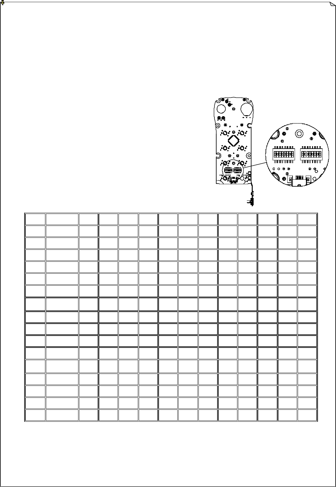
1. System Channel Setting
Fig. 09
Set the receiver channel simply by adjusting the channel dip-switch located on the receiving board located
inside the receiver unit. The system channel table located on page 19 will tell you which dip setting
correspond to which channel. Do make sure that when you change the channel of the receiver you must
also change the channel of the transmitter as well. The channel on both transmitter and receiver must be
identical in order for the system to work.

14
2. Output Relay Configurations
1. 3 Relays per Motion – Shared 2nd Speed Rely
For connections with output relay configuration as Forward 1st speed (F1), Reverse
1st speed (R1) and Forward/Reverse 2nd speed (F/R2). Forward and Reverse 2nd
speed (F/R2) shared the same output.
2. 4 Relays per Motion (Type A) – Separate 1st and 2nd Speed Relay
For connections with output relay configuration as Forward 1st speed (F1), Reverse
1st speed (R1), Forward 2nd speed (F2) and Reverse 2nd speed (R2). Forward and
Reverse 2nd speed its own output.
3. 4 Relays per Motion (Type B) – Shared 1st and 2nd Speed Relay
For connections with output relay configuration as Forward motion (F), Reverse
motion (R), Forward/Reverse 1st speed (F/R1) and Forward/Reverse 2nd speed
(F/R2).
4. 3-Relay Configuration with Close/Close Contact at 2nd Speed
At 2nd speed, both 1st and 2nd speed output relays are activated or closed (F+FR2 or
R+FR2 relays activated).
5. 4-Relay (Type-A) Configuration with Open/Close Contact at 2nd Speed
At 2nd speed, only 2nd speed output relay is activated or closed (F2 or R2 relay
activated)
6. 4-Relay (Type-A) Configuration with Close/Close Contact at 2nd Speed
At 2nd speed, both 1st and 2nd speed relays are activated or closed (F+F2 or R+R2
relays activated)
7. 4-relay (Type-B) Configuration with F/FR2 Contact at 2nd Speed
At 2nd speed, both forward/reverse motion and 2nd speed relays are closed (F+FR2 or
R+FR2 relays activated)
8. 4-Relay Configuration with F/FR1/FR2 Contact at 2nd Speed
At 2nd speed, forward motion, forward/reverse 1st speed and forward/reverse 2nd
speed relays are close ( F+FR1+FR2 relays activated)
9. ON/OFF Function
The user can set the two adjacent push buttons to act as an ON & OFF power switch.
Pressing the OFF button will activates the OFF output relay and deactivates the ON output
relay.

15
10. Magnet ON/OFF Function
The user can set the two adjacent push buttons to control a magnet. To activate the magnet
just press the button with the Magnet symbol. To deactivate the magnet, for safety purpose,
you must press and hold the button with the Magnet symbol and press the OFF button.
Pressing the OFF button alone can and will not deactivate the magnet.
11. Brake Function
When the transmitter push button is released from 2nd speed down to 1st speed, electronically,
both 1st and 2nd speed output relays will be deactivated for up to 1.0 second and then with 1st
speed output relay reactivated thereafter.
12. External Warning Function
The user can install an external warning device (rotating lights, horn, etc…) to a special
“function relay” located inside the receiver. The user can choose which push button pairs or
crane motion he wants to have external warnings when push button is pressed. If the
programmed push button is pressed it will activate the function relay thus activating the
external warning device.
13. Momentary Contact
When push button is released the output relay corresponds to that push button will be
deactivated.
14. Toggled (Latching) Contact
When push button is released the output relay corresponds to that push button will remained
activated until next time the user presses the same push button again.
15. 3rd Speed Function
This function allows the crane to travel additional step beyond 2nd speed. At second speed,
pressing the 3rd speed push button will toggle between 2nd and 3rd speed.
16. Auxiliary Stop Function
The special stop function acts as a 2nd emergency stop button. The receiver MAIN will also
be deactivated when this Stop push button is pressed.
16
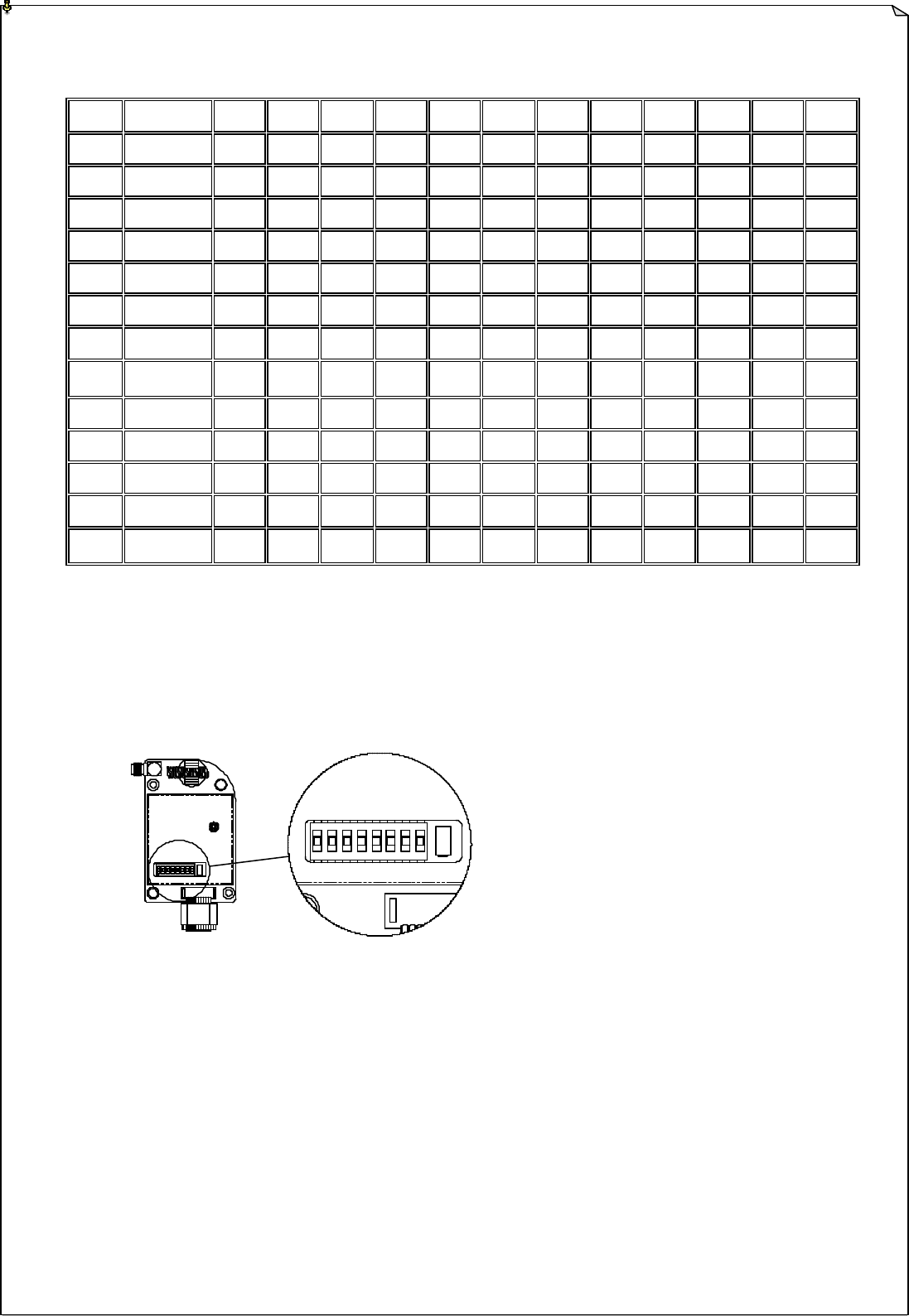
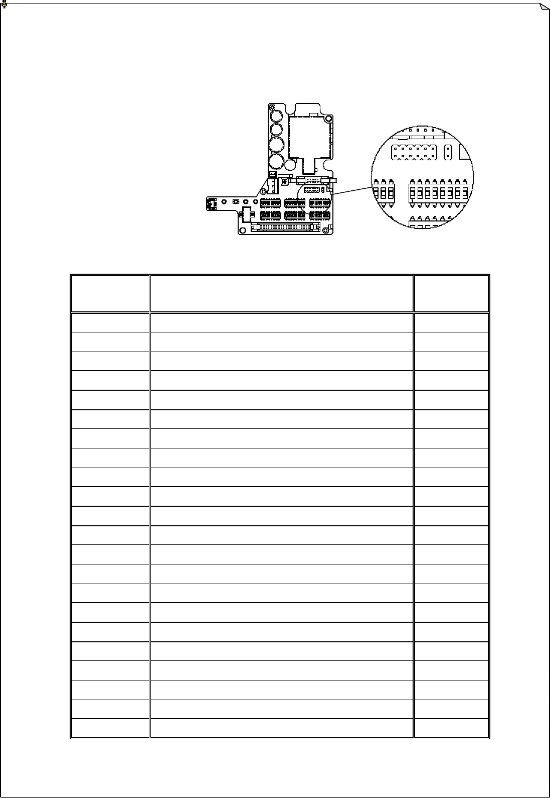
3. Dip-Switch Settings
There are six dip-switches located on the decoder board, which is one dip-switch per motion or
push button pair (1 dip-switch per left and right push button).
Fig. 10
Dip Settings
Relay Functions # of Relays
Used
0000001 Closed/Closed Relay Action at 2nd Speed 4
0000010 Closed/Closed Relay Action at 2nd Speed 3
0000011 Opened/Closed Relay Action at 2nd Speed 4
0000100 F/FR2 Relay Action at 2nd Speed 4
0000101 F/FR1/FR2 Relay Action at 2nd Speed 4
0000110 On/Off 2
0000111 Magnet On/Off 2
0010001 Closed/Closed Relay Action + External Warning 4
0010010 Closed / Closed Relay Action + External Warning 3
0010011 Opened/Closed Relay Action + External Warning 4
0010100 F/FR2 Relay Action + External Warning 4
0010101 F/FR1/FR2 Relay Action + External Warning 4
0100001 Closed/Closed + Brake 4
0100010 Closed/Closed Relay Action + Brake 3
0100011 Opened/Closed Relay Action + Brake 4
0100100 F/FR2 Relay Action + Brake 4
0100101 F/FR1/FR2 Relay Action + Brake 4
0110001 Closed/Closed Relay Action + Brake + External Warning 4
0110010 Closed/Closed Relay Action + Brake + External Warning 3
0110011 Opened/Closed Relay Action + Brake + External Warning 4
0110100 F/FR2 Relay Action + Brake + External Warning 4
0110101 F/FR1/FR2 Relay Action + Brake + External Warning 4

17
Dip-Switch Settings - Continued
Dip Settings
Relay Function for the
Left Push Button
Relay Function for the
Right Push Button
# of Relays
Used
1000000 Momentary Contact Momentary Contact 2
1001000 Toggled Contact Momentary Contact 2
1000001 Momentary Contact Toggled Contact 2
1001001 Toggled Contact Toggled Contact 2
1000010 Momentary Contact 3rd Speed 2
1001010 Toggled 3rd Speed 2
1010000 3rd Speed Momentary Contact 2
1010001 3rd Speed Toggle Contact 2
1000111 Momentary Contact Auxiliary Stop 2
1001111 Toggled Contact Auxiliary Stop 2
1010111 3rd Speed Auxiliary Stop 2
1111000 Auxiliary Stop Momentary Contact 2
1111001 Auxiliary Stop Toggled Contact 2
1111010 Auxiliary Stop 3rd Speed 2
18
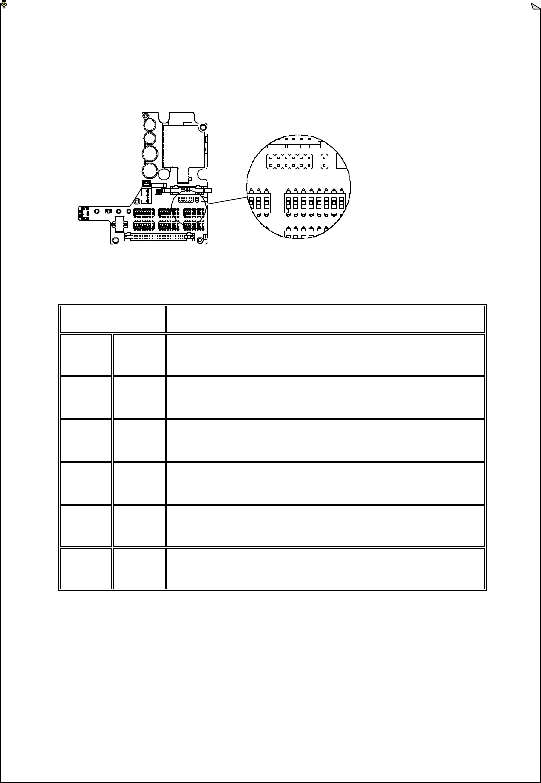
4. Jumper Settings
Jumper settings are applied to functions such as MAIN cutoff time, system startup and
transmitter push button layout. The jumpers are located on top of the dip-switches.
Fig. 11
Jumper Settings
Function
JP1
(Blank)
JP2
(Blank)
Receiver MAIN never deactivates unless transmitter power is turned off or
emergency stop command is initiated
JP1
(Inserted)
JP2
(Blank) Receiver MAIN deactivates automatically after 5 minutes of inactivity.
JP1
(Blank)
JP2
(Inserted)
Receiver MAIN deactivates automatically after 30 minutes of inactivity.
JP1
(Inserted)
JP2
(Inserted)
Receiver MAIN deactivates automatically after 60 minutes of inactivity.
JP4
(Blank)
JP5
(Blank) Normal right-to-left push button configuration
JP4
(Blank)
JP5
(Inserted)
In-line push button configuration (top to bottom)

19
5. System Channel Table
Channel Dip Setting Channel Dip Setting
I-CHIP 000000 note A 32 100000
01 000001 33 100001
02 000010 34 100010
03 000011 35 100011
04 000100 36 100100
05 000101 37 100101
06 000110 38 100110
07 000111 39 100111
08 001000 40 101000
09 001001 41 101001
10 001010 42 101010
11 001011 43 101011
12 001100 44 101100
13 001101 45 101101
14 001110 46 101110
15 001111 47 101111
16 010000 48 110000
17 010001 49 110001
18 010010 50 110010
19 010011 51 110011
20 010100 52 110100
21 010101 53 110101
22 010110 54 110110
23 010111 55 110111
24 011000 56 111000
25 011001 57 111001
26 011010 58 111010
27 011011 59 111011
28 011100 60 111100
29 011101 61 111101
30 011110 62 111110
31 011111 Reserved 111111
Note A: When set to all “0” the priority goes to the channel assigned inside the I-CHIP
Note B: Use only dip position #1 through position #6 for system channel setting.
20
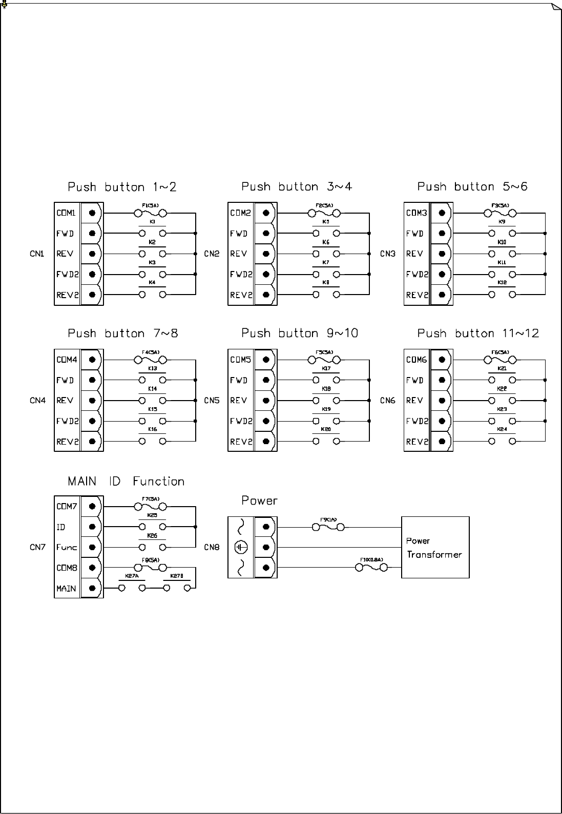
6. Receiver Installation
A. OUTPUT RELAY CONTACT DIAGRAM
Fig. 12
21
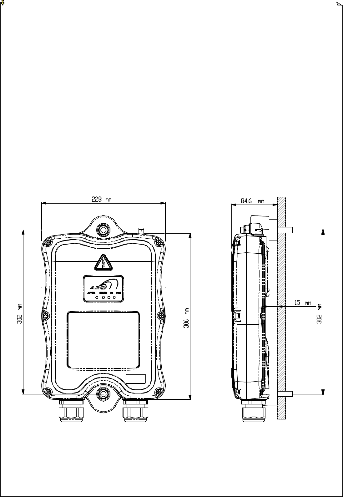
B. RECEIVER MOUNTING
1. Pre-installation Precautions
1. Make sure that the transmitter and receiver are with identical serial number, channel and ID
code.
2. Make sure the receiver is not set to the same channel as any other systems in use in the
surrounding area.
3. Prior to installation, make sure that the crane or equipment is working properly prior to
installation.
4. Make sure the power source to the receiver is set correctly.
5. Prior to installation, switch off the main power source to the crane or equipment.
Fig. 13

22
2. Step-By-Step Installation
1. For better reception, the location of the receiver should be visible to the operator at all time.
2. The location selected should not be exposed to high levels of electric noise. Mounting the
receiver next to an unshielded variable frequency drive may cause minor interference.
Always locate the receiver as far away from variable frequency drive as possible .
3. Ensure the selected location has adequate space to accommodate the receiver.
4. Make sure the receiver is in upright position.
5. Drill two holes (10mm in diameter) on the control panel or location where the receiver is to be
installed (Refer to Fig. 13 on page 21).
6. Make sure the bolts are tightened after installation.
7. For system wiring please refer to Fig.12 on page 20.
3. System Testing
1. Turn on the power source to the receiver and test the MAIN relay output by pressing the red
emergency stop button and observe that it properly opens and closes the main line
disconnect contactor.
2. Test the operation of each function to ensure it corresponds to the transmitter direction labels
or the pendent it is replacing.
3. Test the limit switches to see if they are working properly.
4. If your new remote control is replacing an existing pendant, make sure it is completely
disconnected and placed in a safe location to prevent unwanted control command.

23
7. Operation Procedure
A. TRANSMITTER OPERATION
a. Reset the emergency stop button located on the top left hand side of the transmitter handset by
rotating it either clockwise or counter clockwise, the red button will pop up.
b. Turn on the transmitter power by inserting the black-colored key onto the power key slot located on
the top right hand side of the transmitter handset and rotate it clockwise to “On” position.
c. After turning on the transmitter power, the green light on the transmitter status LED will light up for
up to 2 seconds, which means that the system is ok. If the green light did not appear on the Status
LED, then please refer to “Status Light Indicators & Warnings” on page 24.
d. If there are no signs of any system irregularities, then rotate the power key further clockwise to
“Start” position for up to 1 second, this will activate the receiver MAIN. The power key will
retract back to “On” position automatically after release.
e. Now press any push button on the transmitter handset to operate the crane or equipment.
f. In case of an emergency press down the red emergency stop button will immediately disconnect the
receiver mainline. The transmitter status LED will blink red (refer to page 24). To reset the
emergency stop button just rotate the red button either direction, it will pop up. Then rotate the
power key to “start” to resume operation (MAIN activated).
g. To turn off the transmitter handset, just rotate the power key to “Off” position, it will disconnect the
transmitter power and the receiver MAIN altogether.
h. Change batteries simply by unscrew the battery cover located on the back side of the transmitter
handset.

24
B. STATUS LIGHT INDICATORS & WARNINGS
1. Transmitter STATUS Light Indication
Type Display Type Indication
Voltage below 2.3V at initial power on,
transmitter shuts off, change batteries
1 Constant red Voltage below 1.8V during operation,
transmitter shuts off, change batteries
2
Blinking red
“on” → 0.15 second
“off” → 1.85 seconds
Voltage below 2.2V during operation, warning,
change batteries suggested
3 2 red blinks followed by a
1.85-second pause (off)
The pushbutton
jammed or defective
4 3 red blinks followed by a
1.85-second pause (off) EEPROM error
5 4 red blinks followed by a
1.85-second pause (off)
Transmitting error, system can not locked on
to the designated channel
6 Constant green for 2 seconds Transmitter power on prior to initiating the
START function
7 Blinking green at every 2-second
interval When pushbutton is pressed, signal transmitted
8
Blinking red
“on” → 1.0 second
“off” → 1.0 second
Stop command initiated with MAIN
disconnected
25
2. Receiver STATUS Light Indication
Type Display Type Indication
1 Blinking red Stop command initiated with MAIN
disconnected
2 Blinking green (fast) Decoding in process
3 Blinking green (slow) Decoding on standby
3. Receiver SQ Light Indication
Type Display Type (Red) Indication
1 On Transmission received
2 Off No transmission
3 Blinks intermittently (fast) Other radio interference
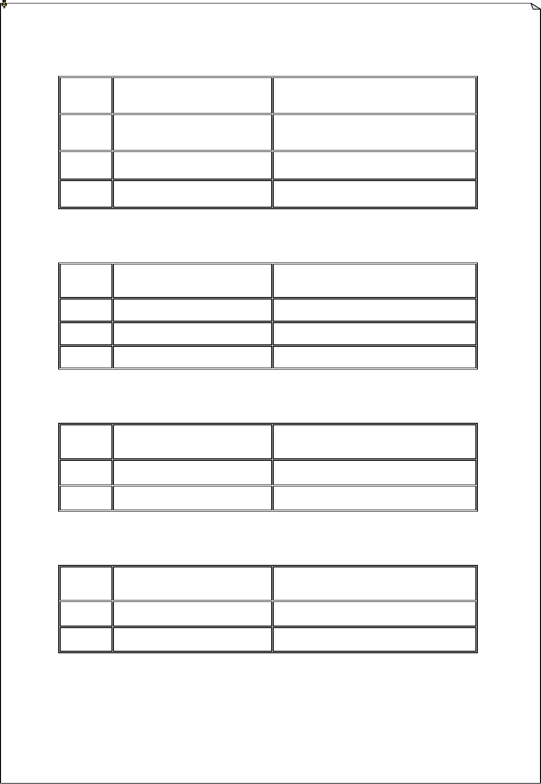
4. Receiver POWER Light Indication
Type Display Type (Red) Indication
1 On Power to receiver
2 Off No power to receiver
5. Receiver COM Light Indication
Type Display Type (Red) Indication
1 On Power to relay board
2 Off No power to relay board
26
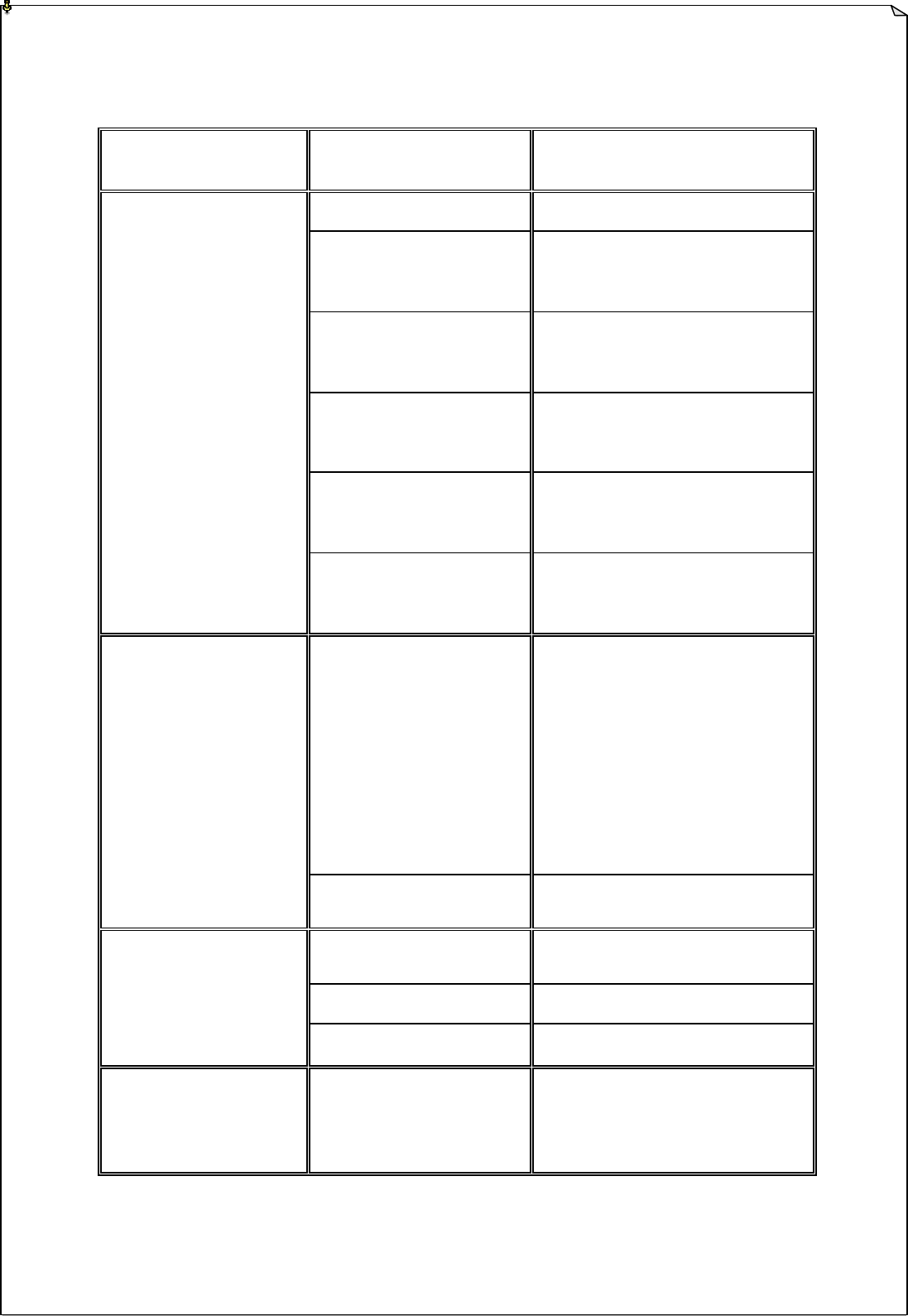
C. TROUBLE SHOOTING TIPS
Problems Possible Causes Recommendation
Transmitter low battery power
Check the transmitter battery level
Emergency stop button
activated prior to startup
Prior to turning on the transmitter power
switch make sure that the red emergency
stop button is elevated.
Improper startup procedure
Redo the startup procedure by holding
the power key at “START ” position for
up to 1.0 second and then release
Incorrect system RF channel
Check and make sure that the transmitter
handset and receiver unit both have the
same system RF channel
Incorrect system ID code
Check and make sure that the transmitter
handset and receiver unit both have the
same system ID code
No responds when
transmitter push
button is pressed
(Improper startup & settings)
System out of range
Make sure that the startup procedure
must be done within 150 feet from the
receiver location
Defective transmitter and
receiver RF board
Check the SQ display on the face of the
receiver unit. If it does not light up
when push button is pressed then either
the transmitter or receiver RF board is
defective. First replace the transmitter
RF board. If SQ display still not lid
when push button is pressed then the go
ahead and replace the receiver RF
board.
No responds when
transmitter push
button is pressed
(Damaged hardware)
Defective transmitter encoder
board
If still no responds, then replace the
transmitter encoder board.
Incorrect input voltage Make sure the source voltage is set
correctly
Blown fuse Check for any blown fuse
No AC power to
the receiver
Incorrect wiring Check input voltage connection
Outputs do not
correspond to
transmitter
Incorrect output connection
Check the entire system wiring again.
Please refer to the output diagram on the
face of the receiver unit

27
8. System Specifications
Frequency Range : 433~434 MHz
Number of Channels : 62 channels adjustable
Channel Spacing : 25 KHz
Modulation : Digital Frequency Modulation based on Manchester
Code, 20bit address, 32bit CRC Parity Check and
Hamming Code.
Decoder : Microprocessor-controlled
Hamming Distance : 4
Frequency Control : Synthesized PLL (Phase Lock Loop)
Receiver Sensitivity : -112dBm
Spurious Emission : -50dB
Antenna Impedance : 50 ohms
Transmitting Power : 0.25mW
Enclosure Rating : IP-66
Output Contact Rating : 250V @ 10 Amps
Transmitter Operating Voltage : 3.0V
Receiver Power Consumption : 11.0 VA
Operating Temperature : -13℉ ~ 167℉
Transmitter Dimension : 23.cm (L) x 6.9cm (W) x 3.5cm (H)
Receiver Dimension (All Models) : 36.3cm (L) x 22.8cm (W) x 7.0cm (H)
Transmitter Weight : 12.5 ounce (include batteries)
Receiver Weight (All Models) : 5.5 pound
Number of Motions : Up to 6 Motions (12 pushbuttons)

28
9. Spare Parts
1. Transmitting Board (433/434MHz) TRB 01
2. Encoder Board (complete with push buttons) ENB 06
3. I-CHIP (complete) ICP 01
4. Receiver Board RVB 01
5. Decoder Board DEB 01
6. Receiver Relay Board RLB 06
7. AC Line Filter Board LFB 01
8. Power Transformer PTF 01
9. Transmitter Top Casing TTC 03
10. Transmitter Bottom Casing TBC 03
11. Transmitter Battery Cover TBC 04
12. Receiver Top Casing RTC 01
13. Receiver Bottom Casing RBC 01
14. Cord Grip / Cable Gland CGR 01
15. Shock Absorber SAB 01
16. 2-Speed Push Button PBN 02
17. 3-Stage Selector Switch SWT 01
18. Push Button Rubber Boot PRB 01
19. Emergency Stop Button EMS 01
20. Transmitter Power Keys Switch PWK 01
21. Waist Belt WBT 01
22. Waist Belt Ring WBR 01
23. Safety MAIN relay SMR 01
24. Regular Output Relay RLY 01
25. Dust Cover CVR 03