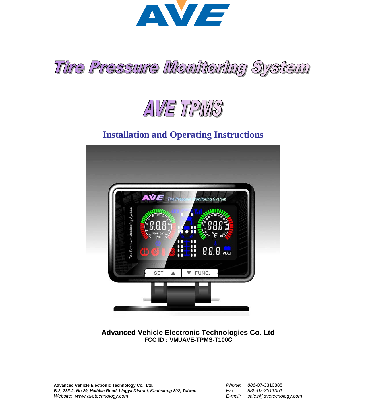
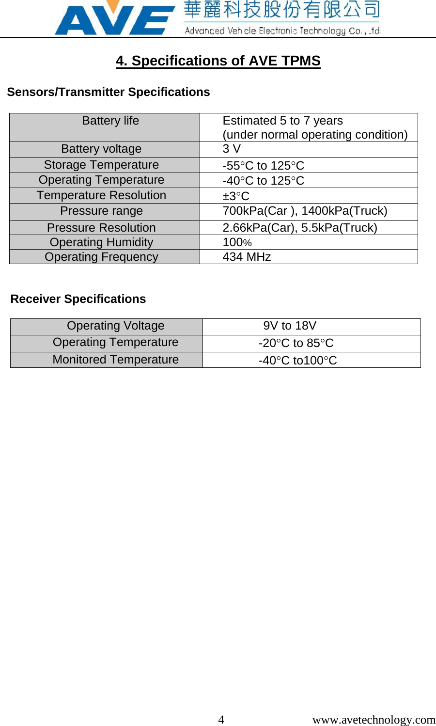
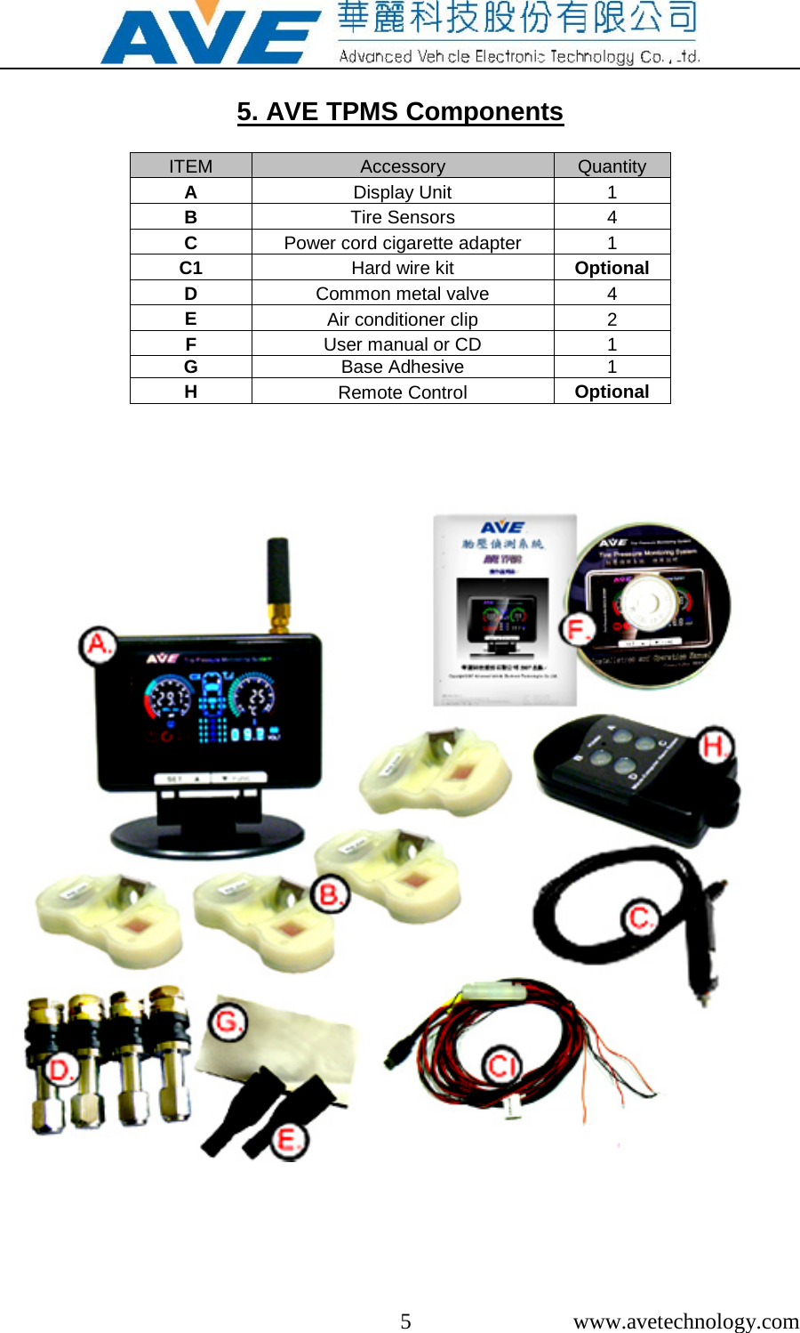
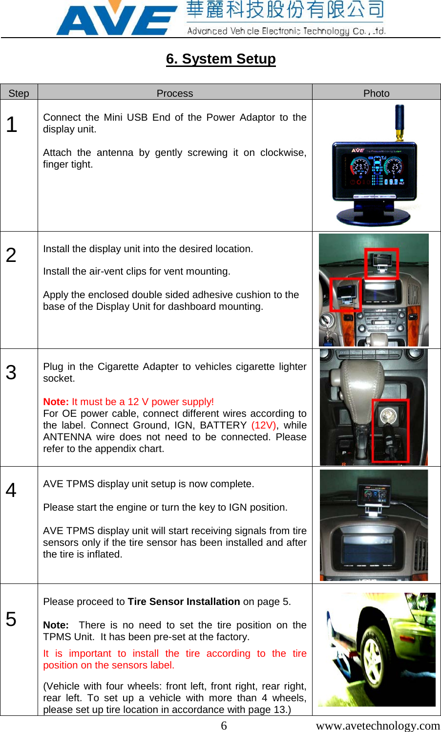
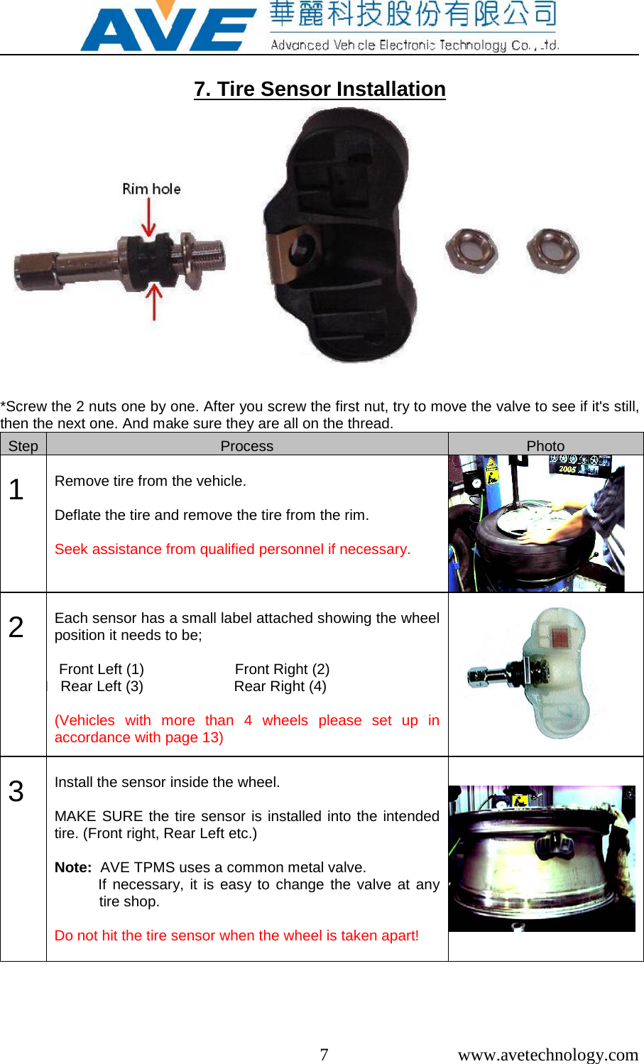
Advanced Vehicle Electronic Technology AVE-TPMS-T100C TPMS User Manual AVE TECHNOLOGY TPMS MANUAL

Advanced Vehicle Electronic Technology Co., Ltd. TPMS AVE TECHNOLOGY TPMS MANUAL

User manual

Advanced Vehicle Electronic Technology Co., Ltd. Phone: 886-07-3310885 B-2, 23F-2, No.29, Haibian Road, Lingya District, Kaohsiung 802, Taiwan Fax:  886-07-3311351 Website: www.avetechnology.com  E-mail: sales@avetecnology.com Installation and Operating Instructions  Advanced Vehicle Electronic Technologies Co. Ltd FCC ID : VMUAVE-TPMS-T100C
 1  www.avetechnology.com  TABLE OF CONTENTS    1.  AVE Tire Pressure Monitoring System (TPMS) ……………………   2   2.  Notice  ……………………………………………………………………   2   3.  Caution ……………………………………………………………………   3   4.  Specifications of AVE TPMS  ……………………………………   4   5.  AVE TPMS Components  ……………………………………………   5   6.  System Setup ……………………………………………………………   6    7.  Tire Sensors Installation  ……………………………………………   7   8.  Display Unit Introduction  ……………………………………………   10   9.  Operating AVE TPMS     9-1. Operating Mode     ………………………………………………  12   9-2. Function Mode (To review every tire’s condition quickly)……  12   9-3. Unit Mode (To review every tire’s condition quickly)…….……  13   9-4. Pressure setup mode (To change vehicle mode & pressure) …  14   9-5. Setup the 2nd Standard Pressure ……………………………..   16   9-6. Match Tires and the 1st or 2nd Standard Pressure…..………  16   9-7. Mount/Dismount the Trailer ……………………………………   16   9-8. Tire setup mode (To change/rotate tires)   ….………………   17   9-9. Set up sensor position   ………………………………………..   18   9-10. Reacting to Alerts …….………………………………………..   19 10.  LF Remote Control  ………………...…………………………………..  22 11. Chart of Tire Setup Mode and Leak Test   ……………………………  23 12. AVE TPMS Extended Antenna Cable   ………………………………..   24 13.  AVE TPMS Optional Accessories ……………………………………  25 14.  Appendixes  ……………………………………………………………  26 15.  Warranty   ……………………………………………………………  27
2  www.avetechnology.com 1. AVE Tire Pressure Monitoring System (TPMS)Thank you for purchasing AVE’s Tire Pressure Monitoring System (TPMS). AVE’s TPMS was designed to provide you with extra protection while driving. Our TPMS informs you of tire pressure and tire temperature and immediately notifies you of any problems such as a slow or fast leak.  After proper installation, AVE’s TPMS will continually monitor your vehicles’ tire pressure and temperature with accurate and up-to-date information.  If the TPMS detects any irregularity in the tires’ pressure and/or temperature, it will immediately sound an alarm and flash on the LCD display to notify the driver.  Prompt action needs to be taken to avoid accidents and ensure the safety of the driver and their passenger. 2. NoticeFCC Notice This device complies with part 15 of the FCC Rules. Operation is subject to the following two conditions: (1) This device may not cause harmful interference, and (2) this device must accept any interference received, including interference that may cause undesired operation.This equipment has been tested and found to comply with the limits for Class B devices, pursuant to part 15 of the FCC rules. These limits are designed to provide reasonable protection against harmful interference. This equipment can radiate radio frequency energy and if not installed and used in accordance with the instructions, may cause harmful interference to radio communications. However, there is no guarantee that interference will not occur in a correct installation.  If this equipment does cause harmful interference to radio and television reception, which can be determined by turning the equipment off and on, the user is encouraged to try to correct the interference by one or more of the factoring measures. •Reorient or relocate the receiving antenna•Increase the separation between the equipment the system•Change the place and connection way of receiver.Attention Any changes or modifications in construction of this device could void the user’s authority to operate the equipment. To comply with the FCC RF exposure compliance requirements, this device’s  antenna must not be co-located or operating to conjunction with any other antenna or transmitter.
 3  www.avetechnology.com  3. CAUTION   • AVE’s TPMS system is designed to monitor the tires condition and alert the user if there is any irregularity detected.  • Use of chemical sealants for temporary resealing or re-inflation in tire assembly may affect or even damage the sensors function.   • For your own safety, please read and understand the instruction manual before proceeding to the installation and setup.  • Please seek qualified personnel for proper tire sensor installation.  •  Only use the power cord cigarette adapter supplied by AVE Technology.  • Do not use AVE Technologies power cord in any other USB device. It is NOT USB compatible and may damage your USB device.   • AVE TECHNOLOGY shall not be held responsible for any damage caused to any USB device if you use this power adaptor in any other device.  • When you unplug the power adaptor, do not pull from the cord. It may damage the adaptor.  • If the power cable is damaged in any way, and is under warranty, contact your dealer.  • Never try to disassemble or repair the product yourself.
 4  www.avetechnology.com  4. Specifications of AVE TPMS    Sensors/Transmitter Specifications  Battery life Estimated 5 to 7 years  (under normal operating condition) Battery voltage 3 V Storage Temperature -55°C to 125°C Operating Temperature -40°C to 125°C Temperature Resolution ±3°C Pressure range 700kPa(Car ), 1400kPa(Truck) Pressure Resolution 2.66kPa(Car), 5.5kPa(Truck) Operating Humidity 100% Operating Frequency 434 MHz      Receiver Specifications   Operating Voltage 9V to 18V Operating Temperature -20°C to 85°C Monitored Temperature -40°C to100°C
 5  www.avetechnology.com  5. AVE TPMS Components  ITEM Accessory Quantity A Display Unit 1 B Tire Sensors 4 C Power cord cigarette adapter 1 C1 Hard wire kit Optional D Common metal valve 4 E Air conditioner clip 2 F User manual or CD 1 G Base Adhesive 1 H Remote Control Optional
 6  www.avetechnology.com  6. System Setup  Step Process Photo  1          Connect the Mini USB End of the Power Adaptor to the display unit.   Attach the antenna by gently screwing it on clockwise, finger tight.    2         Install the display unit into the desired location.   Install the air-vent clips for vent mounting.  Apply the enclosed double sided adhesive cushion to the base of the Display Unit for dashboard mounting.   3         Plug in the Cigarette Adapter to vehicles cigarette lighter socket.  Note: It must be a 12 V power supply! For OE power cable, connect different wires according to the label.  Connect Ground, IGN, BATTERY (12V),  while ANTENNA wire does not need to be connected. Please refer to the appendix chart.      4         AVE TPMS display unit setup is now complete.   Please start the engine or turn the key to IGN position.  AVE TPMS display unit will start receiving signals from tire sensors only if the tire sensor has been installed and after the tire is inflated.     5         Please proceed to Tire Sensor Installation on page 5.   Note:  There is no need to set the tire position on the TPMS Unit.  It has been pre-set at the factory.   It is important to install the tire according to the tire position on the sensors label.  (Vehicle with four wheels: front left, front right, rear right, rear left. To set up a vehicle with more than 4 wheels, please set up tire location in accordance with page 13.)
 7  www.avetechnology.com  7. Tire Sensor Installation  *Screw the 2 nuts one by one. After you screw the first nut, try to move the valve to see if it's still, then the next one. And make sure they are all on the thread. Step Process Photo  1      Remove tire from the vehicle.  Deflate the tire and remove the tire from the rim.  Seek assistance from qualified personnel if necessary.     2       Each sensor has a small label attached showing the wheel position it needs to be;  Front Left (1)                      Front Right (2) I   Rear Left (3)                      Rear Right (4)  (Vehicles with more than 4 wheels please set up in accordance with page 13)   3       Install the sensor inside the wheel.  MAKE SURE the tire sensor is installed into the intended tire. (Front right, Rear Left etc.)  Note:  AVE TPMS uses a common metal valve.   If necessary, it is easy to change the valve at any tire shop.  Do not hit the tire sensor when the wheel is taken apart!
 8  www.avetechnology.com   4       Be sure the rubber seal is properly positioned between the rim and the valve.       5       Clean the inside of the tire from any dust and inflate the tire to the proper pressure as recommended by the tire manufacturer.  The tire must be inflated to the proper tire pressure to activate the tire sensor.   Pressure unit kpa psi bar 700Kpa 260 37.7 2.6 1400Kpa 560 81.2 5.6    6       Tires MUST be balanced after the tire sensor has been properly installed.    Tires must be balanced by professional personnel.    Be sure to install the tire into the proper location as per the tire sensor.  If you fail to do this, the TPMS unit will give you readings from the wrong location.    7       Follow the above procedure for the other 3 tires.      8        Once the tire sensors have been properly installed, connect the display unit to vehicles cigarette lighter power.  AVE TPMS will then detect signals from the tire sensors.           If there is no signal, disconnect the power to the display unit, re-connect it and try again.  If there is still no display, try a third time.  If after the third try you still have no signal please reset the display unit.   (Please refer to Tire Setup Mode on page 19)  Note: There is no need to setup up the tire location as it is                                          preset at the factory. (This is only applicable if the tire installation is according to the position on the sensors label.)
 9  www.avetechnology.com Anti-theft installation of external sensor  1. (Left→Right) Anti-theft nut, Original metal valve on car, External sensor 2. Take off the cap of valve, and screw the nut on valve 3. Install the external sensor on valve by hand, and use wrench to screw the nut opposite way up, until you can’t easily take off the cap by hand. Please avoid using any other tool to touch the external sensor, in order not to destroy the structure. Notice: You can soap liquid test after installation to make sure they don't leak. (A complete external sensor is water-proof outside)
 10  www.avetechnology.com 8. Display Unit Introduction     No. Description Photo  1   Sensor battery icon  Measures the Tire Sensor battery level    2    Signal strength icon  Measures the signal strength from the tires sensor.    3     Vehicle battery reading  Monitors the vehicles battery  (in operating mode)  (If it is above 15.5V or below 11.5V, it will flash and has a warning sound)
 11  www.avetechnology.com  4    Pressure Warning icon  Will light when the Tire Sensor detects any irregularities in Tire Pressure . i.e.:. Fast/Slow leak, tire pressure above or below 30% of recommended pressure    5    Flat tire icon  Will light when flat tire is detected.    6     High Temperature Icon  Will light when the temperature inside the tire is above 85°C (185°F)    7         Wheel types (car or truck mode)    • Up to 8 modes of vehicle type selection • Programmable up to 27 tires. • Optional monitoring for spare tire.        8       Pressure Meter  • Measures 3 different pressure units (KPa, bar, psi)  • Color difference to differentiate between normal (Green) and warning (Red)  • Displays actual pressure value on display unit.  Note: Before receiving the signal, it shows last recorded pressure.     9       Temperature Meter  • Measures degrees Celsius (°C) or Fahrenheit (°F) • Different colours to differentiate between normal (green) and high temperature (red) • Displays actual temperature value on the display unit. Note: Before receiving the signal, it shows last recorded temperature.
 12  www.avetechnology.com  9. Operating AVE TPMS  9-1. OPERATING MODE   AVE TPMS display unit will monitor each tire for 10 seconds and then proceed to the next tire.   Problematic tire will be monitored for 15 seconds before proceeding to the next tire. It will keep displaying the warning code until the problem has been taken care of by the user.  For the alerts/warnings codes, please refer to the Reacting to Alerts section.  The tire being monitored will light and its information will be displayed.  ( i.e.:  pressure, temperature, tire sensor battery level and signal strength)  Note: User has the option to turn off the beeping sound by pressing   button.     9-2. FUNCTION MODE (To review every tire’s condition quickly)    Press      button once to enter FUNCTION MODE.  Message area will display FUN.  Press    for next tire selection.  Press    for previous tire selection.  To exit, do not touch the display unit for 20 seconds.  Note:   If there is 20 seconds or more of inactivity, the system will quit the FUNCTION MODE and return to OPERATING MODE.
 13  www.avetechnology.com  9-3. UNIT MODE (To change pressure or temperature unit)  Press and hold    button for 3 seconds to enter UNIT MODE.  1) The message area displays ΔP  2) Psi  icon will light (the default pressure unit or the previously selected unit).  3) Press    to change pressure unit.       ( psi  kpa  bar  psi ) Note:  If Truck pressure is  above 999 kpa, you can only select psi or bar Unit   4) Continue to press    for pressure unit selection. 5) Press    to confirm the selection. Pressure unit is then saved. Note: To bypass pressure unit change, skip step (3) & (4).  Go to step (5) to confirm the default unit settings.  The default pressure unit is in psi or previously selected unit of measure.  To  exit Unit Mode, do not touch any buttons for 20 seconds.  Changes will not be saved (before step 5) and the system will use the default pressure unit.  6) Immediately after step (5), message area will display ΔT. 7) °C  icon will light (default temperature unit or previously selected unit). 8) Press    to change temperature unit. ( °C  °F  °C ) 9) Continue to press    for temperature unit selection. 10) Press    to confirm the selection. Temperature unit is then saved.  11) UNIT MODE setup is now complete. System will automatically return to OPERATING MODE. Note: To bypass temperature unit change, skip step (8) & (9).  Go to step (10) to confirm the default unit settings.  Default temperature unit is in Celsius or previously selected unit  To exit, do not touch any buttons for 20 seconds.    Changes will not be saved (before step 10) and the system will use the default temperature unit.
 14  www.avetechnology.com  9-4. PRESSURE SETUP MODE (To change vehicle mode & pressure)                      Press and hold   button for 3 seconds to enter PRESSURE SETUP MODE. 1) The message area will  display  M01 (The default vehicle mode) or the previously selected mode. 2) Press    to change vehicle mode. ( M01  M02 ~ M08  M01 ) Or press   to keep the default or the previously selected vehicle mode. Then the system will allow you to setup the 2nd standard tire pressure. (Please refer to page 15.) 20 seconds or more of inactivity at this step will exit the setting and get back to the operation  mode. Change will not be launched. 3) Press   to confirm and save the selection of vehicle mode.  Immediately after this  step,  the message area will display the  default  pressure value.  (Default pressure value depends on the vehicle mode selection.) Follow step 4 to confirm or set the standard pressure value.   This step will erase the previously selected vehicle mode and pressure. Moreover, the display will also lose every sensor’s ID code. Afterwards, the leak test will be necessary to launch for reset the sensor ID.                     Vehicle Mode Default pressure (psi) M01  029 M02 039 M03 039 M04 049 M05 049 M06 059 M07 059 M08 059
 15  www.avetechnology.com  4) Press     to accept the default pressure value. 5) Press    to change the pressure value.  6) The pressure value on the far right digit will flash when entering the last digit.  • To change the pressure value, press    button. The displayed number will increase by 1 every time    button is pressed. Continue to press the button until you see the value you want. The number will loop from 0 to 9 and then back to 0.    8)   Press     to accept the input value. The message area will then proceed to the middle number. The pressure value in the middle will flash.  9)    Repeat step (6) to (8)  to set up  2nd, which is the     pressure value on the far left.  10)  Press    to accept the displayed value on the 3rd digit.   Note: If the target pressure value is 28 psi, please enter it as 028 psi. Different unit, if needed, should be selected before setting up the pressure value. Please refer to UNIT MODE on page 12.  Once done, the system will perform a check on the pressure entered. This is to avoid improper pressure setup for selected vehicle mode.  11) If the proper pressure has been entered,   • Message area will display PS (Pressure Saved). • Display Unit will beep once. • Entered pressure value will be saved. • Return to the operating mode.  12)  If improper pressure has been entered, • Message area will display ERR (Pressure Error). • Display Unit will beep twice. • User will automatically be returned to step (6) to re-enter information. • If error (ERR) occurs for the second time, the system will replace the pressure to the default value, and then return to the operating mode.  Note: If the pressure is above 999 kpa, only psi or bar Unit can work. Please refer to Unit Mode (p.12).                      Correctly Enter Pressure                   Error in pressure
 16  www.avetechnology.com  9-5. Setup the 2nd Standard Pressure Value  Only with setting up the standard tire pressure value, the message area will display 2ND, which is to setup the second standard pressure when necessary. The previous setup will be the 1st standard tire pressure value.  1)  To  set up the second standard  pressure value, press   (YES) and  follow the steps (7) to (10) of PRESSURE SETUP MODE on page 14.  2)  To  exit without setting up the second standard  pressure value,  press   (NO) to return to the OPERATING MODE.  10 seconds of inactivity will also  exit this setting and return to the operating mode.    9-6. Match Tires and the 1st or 2nd Standard Pressure   To launch this setting, two different standard pressure values should be done first. In  the operating mode, press and hold   button for 6  seconds, and the message  area displays  SEL (Select 1st or 2nd standard pressure value). Tires in the same row  will flash together, one row by one row. The spare tire will flash individually.  Please press  (SP1) or (SP2) to match every row of tires and the  1st or  the 2nd standard pressure value. The unit will beep once when  matched.  Afterwards, the unit will automatically return to the operating mode.     9-7. Mount/Dismount the Trailer (only for MO2-8 of the vehicle mode)  To launch this setting, tires should be matched with two different standard pressure values first. Press and hold  and  for 9 seconds, and the message  area will display TOW. The trailer part will flash.  1)  Press   (NO) to dismount the trailer. The unit will beep once when dismounted. 2)  Press  (YES) to keep the trailer. The unit will beep once when done.  20 seconds of inactivity, or finishing the trailer mounting/dismounting, will get the unit back to the operating mode.
 17  www.avetechnology.com  9-8. TIRE SETUP MODE (To change/rotate tires)  Press  and hold   and     buttons together for 3 seconds to enter TIRE SETUP MODE. In this mode, message area will display CHG.   Press   (YES) to change tire position and change tire position function.   Pressing  (NO) will not change the tire position and will goes to setting up sensor position.  There are 2 patterns:         (1) Front Wheels and Rear Wheels        (2) Front Right and Rear Left  1) Press   to change patterns.  2) Press   to confirm. Message area will display OK?   Pressing (YES) will display OK and then goes back to operating mode, while pressing  (NO) will display IDX and then goes back to operating mode.  If no any activity for 20 seconds, it will automatically goes to setting up sensor position.  Note:  TIRE SETUP MODE is only for MO1 (Vehicle mode, please refer to page 13).  As any other vehicle mode is picked, TIRE SETUP MODE will not be launched.  TIRE SETUP MODE                 1)  front left and rear left      front right and rear right                2) front right and rear left     front left and rear right
 18  www.avetechnology.com  9-9. Setup the sensor position  It is sometimes necessary to re-set up the sensor position, especially when replacing a tire sensor, replacing a new tire, or mixing up tires after rotating them. To set up the sensor position, follow the steps below:  1) Press and hold the two buttons   and  for 3 seconds. Message area will display  LT (Leak Test)  and the front left tire will flash.  User will have 240 seconds (4 minutes) to perform the leak test on each tire.  2) Inflate or deflate the tire by 34 kpa or 5 psi within 4 minutes. A sudden change in the tire pressure will cause the sensor to transmit signals continuously to let the display learn the sensor position.  3) The display unit will beep once and the message area will show “OK” if the signal is received. The flashing tire on the display unit will stop flashing. Then the front right tire takes  the turn to flash. Follow step 2 to setup the front right tire.  Note: All the tires take turns to be setup in the order 1>2>3>4…..Please refer to page 13 or the tire numbers of each vehicle mode.   4)  To delete a tire, press . The message area will display DEL (tire location doesn’t save) and the unit will beep once. Then message area display “OK?” • Press   to delete this tire if there is no sensor installed or no tire existing in the position. Deleted position will not be monitored by the system. • Press   to skip the leak test on the tire. The message area will display “SKP”. The last default value will be kept.  5) System will proceed to the next tire to set up.  Note: If all tires are completely set up, the system will exit  TIRE SETUP MODE. Inactivity of more than 240 seconds (4 minutes), and the system will automatically return to the operating mode and save the last setting.  Optional to leak test:  User can avoid performing a leak test on the tire by using the Optional  AVE TPMS sensor’s  LF remote control. Kindly refer to the page 21.
 19  www.avetechnology.com  9-10. Reacting to Alerts   NO SIGNAL  • Affected tire will flash during its turn when the unit is in operating mode. • Unit will beep once every second. • Antenna signal Icon shows     with no bars.  • Pressure and Temperature bar indicators will light. • No numbers will be in the Pressure and Temperature display.  Note: Interference will affect signal’s reception.   Press     to turn off the sound.  If the sound is turned off, the Warning will remain on the display until the problem is taken care of by the user.        UNDER-INFLATION (25%)  • Affected tire will flash during its turn when the unit is in operating mode. • Unit will beep once every two seconds • Pressure bar indicator will flash at 75%  Note:  Press      to turn off the sound.  If the sound is turned off, the Warning will remain on the display until the problem is taken care of by the user.  The 25% under-inflation value in pressure display is  based on default 29 psi.      UNDER-INFLATION (30%)  • Affected tire will flash during its turn when the unit is in operating mode. • Unit will beep once every two seconds • Pressure bar indicator will flash at 70% • Tire leak icon will light  Note:  Press      to turn off the sound.  If the sound is turned off, the Warning will remain on the display until the problem is taken care of by the user.  The 30% under-inflation value in pressure display is  based on default 29 psi.
 20  www.avetechnology.com   CAR BATTERY  If the battery voltage falls below 11.5 volts or goes higher than 15.5 volts, the Battery chart will flash and the unit will beep once every two seconds.  Note:  Press      to turn off the sound. If the sound is turned off, the Warning will remain on the display until the problem is taken care of by the user.     OVER-INFLATION (25%)  • Affected tire will flash during its turn when the unit is in operating mode. • Unit will beep once every two seconds • Pressure bar indicator will flash at 75%  Note:  Press      to turn off the sound.  If the sound is turned off, the Warning will remain on the display until the problem is taken care of by the user.  The 25% over-inflation value in pressure display is based on default 29psi.      OVER-INFLATION (30%)  • Affected tire will flash during its turn when the unit is in operating mode. • Unit will beep twice every two seconds • Pressure bar indicator will flash at 70% • Tire leak icon will light  Note:  Press      to turn off the sound.  If the sound is turned off, the Warning will remain on the display until the problem is taken care of by the user.  The 30% under-inflation value in pressure display is based on default 29 psi.                           FAST LEAK  • Affected tire will flash during its turn when the unit is in operating mode. • Unit will beep twice every second. • Tire leak icon will light.   Note:  Press      to turn off the sound.  If the sound is turned off, the Warning will remain on the display until the problem is taken care of by the user.
 21  www.avetechnology.com   NO TIRE PRESSURE   • Affected tire will flash during its turn when the unit is in operating mode. • Unit will beep twice every second • Flat Tire icon will light  Note:  Press      to turn off the sound.  If the sound is turned off, the Warning will remain on the display until the problem is taken care of by the user.     TEMPERATURE ABOVE 80°C (176°F)  • Affected tire will flash during its turn when the unit is in operating mode. • Unit will sound one long beep followed by a one second delay • Temperature icon will light • Temperature bar indicator will flash  Note:  Press      to turn off the sound.  If the sound is turned off, the Warning will remain on the display until the problem is taken care of by the user.    TEMPERATURE ABOVE 90°C (194°F)  • Affected tire will flash during its turn when the unit is in operating mode. • Unit will sound one long beep follow by one short beep and a one second delay. • Temperature icon will light. • Temperature bar indicator will flash.  Note:  Press      to turn off the sound.  If the sound is turned off, the Warning will remain on the display until the problem is taken care of by the user.      TEMPERATURE ABOVE 100°C (212°F)  • Affected tire will flash during its turn when the unit is in operating mode. • Unit will sound one long beep followed by two short beeps and a one second delay. • Temperature icon will light. • Temperature bar indicator will flash.   Note:  Press      to turn off the sound. If the sound is turned off, the Warning will remain on the display until the problem is taken care of by the user.
 22  www.avetechnology.com  10. LF Remote Control   In order to simply the complicated procedure of resetting the sensor position by inflating/deflating the wheels when rotating or changing the tires, Remote Control is the best choice.  Without an LF Remote control, please rapidly inflate or deflate the tires, which functions the same as pressing the button B of the LF Remote control.  Set/Reset the sensor position with LF  Setting the sensor position: 1. First, press and hold the  buttons on the display   and    together  for 3 seconds to enter TIRE SETUP MODE. It will display “CHG” and then press   (NO) to learn the ID CODE of the sensors, while the message area will display “LT” (Leak Test) and the front left tire will flash. (TIRE SETUP MODE is only launched for MO1, p.13.) 2. Press the learning key “B” of LF (make LF near the valve stem of the front left tire), which will force the sensor to transmit signals so that the display can learn the position of the wheel. The display unit will beep once if the signal is received and the message area will display “OK”, and then the message area will turn to the next tire automatically. Before “OK” displayed, please do not move the LF away from the wheel. Repeat the same for the remaining tires.  Delete/Skip one sensor: Follow step one to enter TIRE SETUP MODE. When “LT”  is displayed on the message area, press   (NO). The message area will display “DEL”. Press  (YES) to delete the tire, or press   (NO) to skip setting the tire. If any sensor is skipped, its previous status will be also kept. Once the tire has been deleted, it should be added back by repeating the procedure of setting sensor position. When the deleted tire is flashing again, learn the ID CODE with an LF or by rapidly deflating/inflating the tire. Spare tire can be deleted or added back in the same way. (Please attend: when you learn the sensor ID into the display, please take other sensors away in the distance of 3 meters to avoid learning the other sensor ID.)  Functions of the four buttons of LF: A. Warning mode: Make sensors transmit signals per second for two minutes. After two minutes the sensors will get into normal mode. B. Walk up mode: Make sensors transfer signals every second for one minute. After one minute the sensors will get into normal mode. C. Normal mode: Make sensors transfer signals every 30 second. D. Sleep mode: Make sensors into sleep mode without transmitting any signal and save the battery’s life. But when the sensor is put in the tire, the sensor will detect having pressure and automatically wake up. So when the sensor is installed in tire and you press D, it will not sleep due to the pressure.
 23  www.avetechnology.com Yes, delete tire 1 Tire 1 flash Don’t set up the tire but confirm to delete the tire. No, don’t delete but skip tire 1 Tire 2 flash Get the remote control near tire 1 and press and hold “B” button for 5 seconds. Tire 3 flash Tire 4 flash  Follow the same steps to get to others 11. Chart of Tire Setup Mode and Leak Test Press and hold for 3 seconds Quit tire change mode and get to tire set up mode Select the tire changing way Confirm the tire change and get to tire set up mode “LT” shown on the right bottom of the display. “CHG” shown on the right bottom of the display. Tire Set Up  Tire Change Mode Set up Tire 1 (NO) (YES) (NO) (YES) (NO)
 24  www.avetechnology.com  12. AVE TPMS Extended Antenna Cable (for Trucks/Buses/Trailers)                Figure 2  Red line = Antenna Cable. Figure 3   Must set the antenna cable to the central area among all the wheels.The far distance between the driver cabinet and the rear tires (like a truck or bus) may cause the poor antenna. Besides, the thickness of the vehicle stamping parts, car window films with volumes of metal material, and so on will also cause the interference with the signal transmitting. To make sure of the signal well-transmitted and well-received, an extended antenna cable would be strongly in need for trucks/buses/trailers.   Make sure the connection is tight enough. Figure 1
 25  www.avetechnology.com  13. AVE TPMS Optional Accessories  Battery Pack (8AA ) • Battery Pack allows display unit to be carried around for easier setup.  • Users do not have to rely on the power from the  vehicles cigarette lighter power cord. • Useful when setting up vehicles with a lot of wheels. • AVE TPMS will support up to 27 wheels  LF Remote control for Tire Sensors • The LF remote control is used to control the tire sensors. The 2 main functions include; ☆Learning Key (A)           Press this key  to  force  the  sensor to transmit a signal without inflating or deflating  the  tire’s pressure to learn the  wheel position.  It also has the function to exchange the tire’s position.      ☆ Sleep Key (D)           It will force  the  sensor into sleep mode so it will save the tire sensor’s battery power.    • This will only work if the sensor is removed from the wheel, or there is no air pressure in the tire.  As soon as the sensor detects air pressure, the sensor will automatically “wake-up”. This is useful when changing tire location (tire rotation) to setup up the tire position. It will force the tire’s sensor to transmit a signal instead of performing the leak test (page 19).  • Use as a diagnostic tool to test the tire’s sensor if a sensor is transmitting a signal.  Standard Valve  • AVE TPMS uses a standard metal valve.  • Common valve which is available anywhere.   • Allows you to replace just the tire valve if it is damaged or broken.  You do not have to replace the entire sensor.  • With other TPMS units, you have to replace both the valve and the sensor if either one is broken or damaged.   Tire’s sensor  • Tire sensor is available for the spare tire.   • To purchase more tire sensors, please contact your AVE TPMS retailer.
 26  www.avetechnology.com  14. Appendix  Pressure Conversion Table                KPa psi bar  KPa psi bar  KPa psi bar  KPa psi bar 10 1.5 0.1  310 45.0 3.1  610 88.5 6.1  910 132.0 9.1 20 2.9 0.2  320 46.4 3.2  620 89.9 6.2  920 133.4 9.2 30 4.4 0.3  330 47.9 3.3  630 91.4 6.3  930 134.9 9.3 40 5.8 0.4  340 49.3 3.4  640 92.8 6.4  940 136.3 9.4 50 7.3 0.5  350 50.8 3.5  650 94.3 6.5  950 137.8 9.5 60 8.7 0.6  360 52.2 3.6  660 95.7 6.6  960 139.2 9.6 70 10.2 0.7  370 53.7 3.7  670 97.2 6.7  970 140.7 9.7 80 11.6 0.8  380 55.1 3.8  680 98.6 6.8  980 142.1 9.8 90 13.1 0.9  390 56.6 3.9  690 100.1 6.9  990 143.6 9.9 100 14.5 1.0  400 58.0 4.0  700 101.5 7.0  1000 145.0 10.0 110 16.0 1.1  410 59.5 4.1  710 103.0 7.1  1010 146.5 10.1 120 17.4 1.2  420 60.9 4.2  720 104.4 7.2  1020 147.9 10.2 130 18.9 1.3  430 62.4 4.3  730 105.9 7.3  1030 149.4 10.3 140 20.3 1.4  440 63.8 4.4  740 107.3 7.4  1040 150.8 10.4 150 21.8 1.5  450 65.3 4.5  750 108.8 7.5  1050 152.3 10.5 160 23.2 1.6  460 66.7 4.6  760 110.2 7.6  1060 153.7 10.6 170 24.7 1.7  470 68.2 4.7  770 111.7 7.7  1070 155.2 10.7 180 26.1 1.8  480 69.6 4.8  780 113.1 7.8  1080 156.6 10.8 190 27.6 1.9  490 71.1 4.9  790 114.6 7.9  1090 158.1 10.9 200 29.0 2.0  500 72.5 5.0  800 116.0 8.0  1100 159.5 11.0 210 30.5 2.1  510 74.0 5.1  810 117.5 8.1  1110 161.0 11.1 220 31.9 2.2  520 75.4 5.2  820 118.9 8.2  1120 162.4 11.2 230 33.4 2.3  530 76.9 5.3  830 120.4 8.3  1130 163.9 11.3 240 34.8 2.4  540 78.3 5.4  840 121.8 8.4  1140 165.3 11.4 250 36.3 2.5  550 79.8 5.5  850 123.3 8.5  1150 166.8 11.5 260 37.7 2.6  560 81.2 5.6  860 124.7 8.6  1160 168.2 11.6 270 39.2 2.7  570 82.7 5.7  870 126.2 8.7  1170 169.7 11.7 280 40.6 2.8  580 84.1 5.8  880 127.6 8.8  1180 171.1 11.8 290 42.1 2.9  590 85.6 5.9  890 129.1 8.9  1190 172.6 11.9 300 43.5 3.0  600 87.0 6.0  900 130.5 9.0  1200 174.0 12.0    Temperature Conversion Table         °C °F  °C °F   °C °F -40 -40.0  20 68.0  80 176.0 -30 -22.0  30 86.0  90 194.0 -20 -4.0  40 104.0  100 212.0 -10 14.0  50 122.0  110 230.0 0 32.0  60 140.0  120 248.0 10 50.0  70 158.0  125 257.0
 27  www.avetechnology.com  15. WARRANTY  AVE Technology warrants to the original end user that the product purchased is free from defects in material and workmanship for a period of one (1) year from the date of original purchase. Should the product fail within the warranty period, it will be replaced or repaired at the option of AVE Technology. AVE Technology reserves the right to replace defected products with either a new or refurbished unit, to be functionally equivalent to new.   The Warranty is void and inapplicable if:  1. the product has been used or handled other than accordance with the instructions in the user manual 2. the product is abused, misused, damaged by accident or neglect 3. the damage is due from being repaired or tampered with by anyone other than an AVE Technology or an authorized AVE Technology repair center. 4. the damage is due from shipping during transit.  The damaged product must be delivered prepaid to AVE Technology or its authorized AVE Technology repair center. The RETURNED PRODUCT MUST BE ACCOMPANIED BY A WRITTEN DESCRIPTION OF THE DEFECT AND A PHOTOCOPY OF THE ORIGINAL PURCHASE RECEIPT. This warranty is valid in the country of purchase  This warranty is limited to the terms stated herein. AVE Technology shall not be liable for any special, incidental or consequential damages relating to the product sold. This Warranty gives you specific legal rights and you may also have other rights which vary from state to state.   -------------------------------------------(Please cut along line)--------------------------------------------------  WARRANTY REGISTRATION FORM Last Name               First Name                                                                               Apartment Number   House Number                               Street Name                                                                                                                  City                   State/Province                                                                                                             Country            Zip/Postal     Phone                                                                                  -         -            Product                  Model                                                                                                               Warranty           Purchase Date                   1 Year    2 Years                                                                           YEAR  MO  DD

Navigation menu