Advantech Co ARK-1382 Ultra-compact System User Manual ARK 1382 user manual ed 1
Advantech Co Ltd Ultra-compact System ARK 1382 user manual ed 1
UserManual.wiki
>
Advantech Co
>
ARK 1382 User Manual
User manual
Navigation menu
Upload a User Manual
Namespaces
Wiki Guide
HTML
PDF
Info
Views
User Manual
Discussion / Help
Navigation

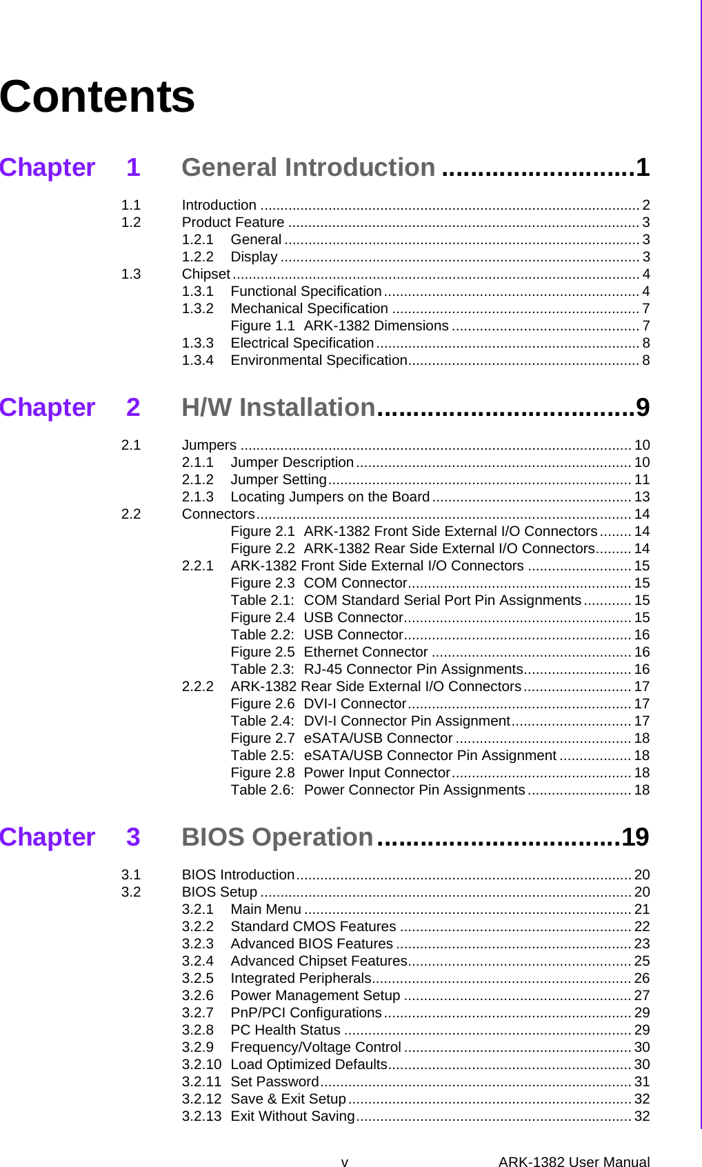
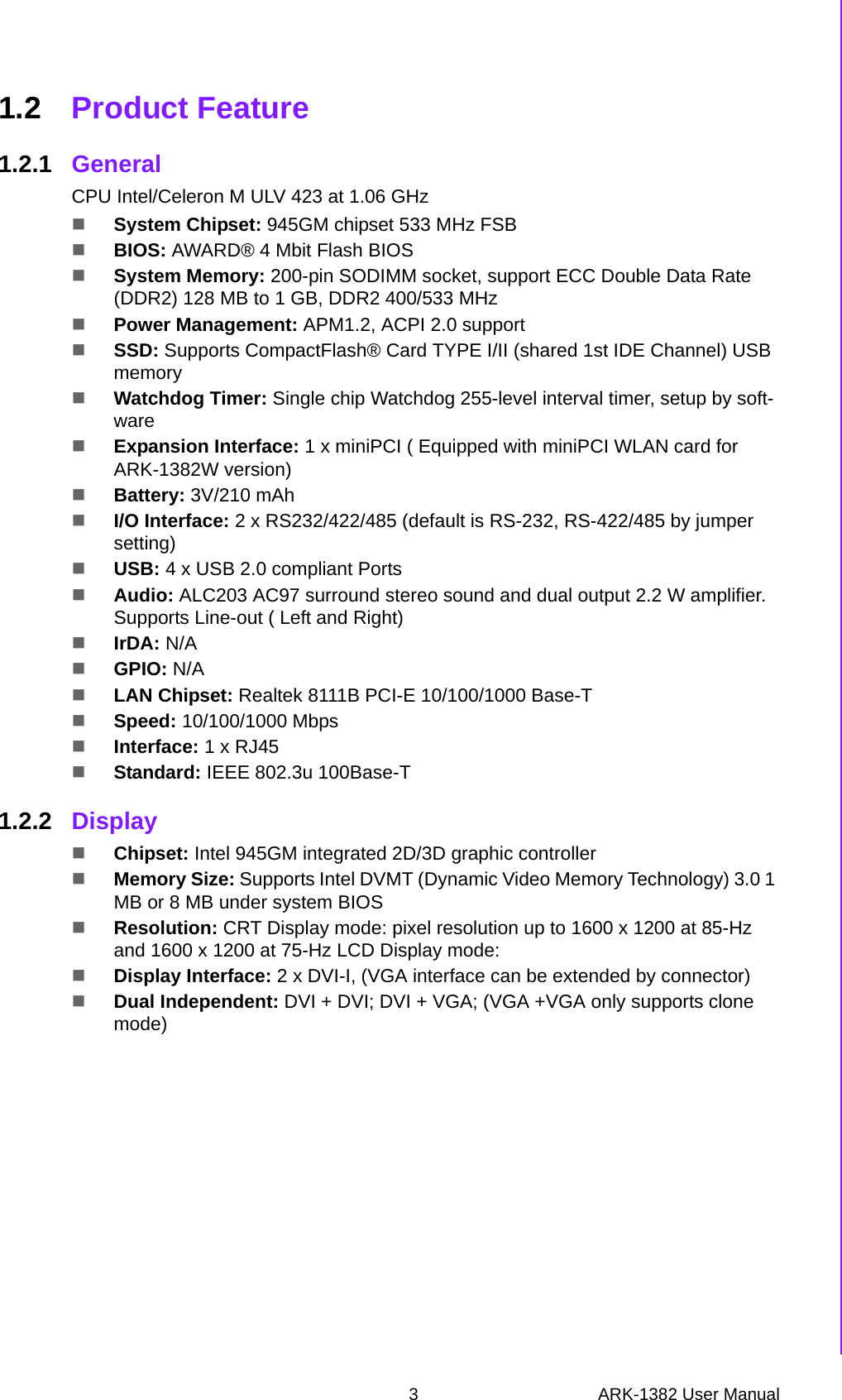
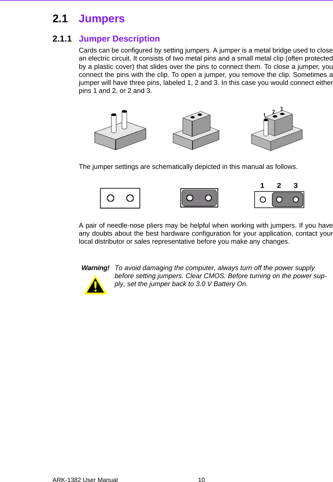
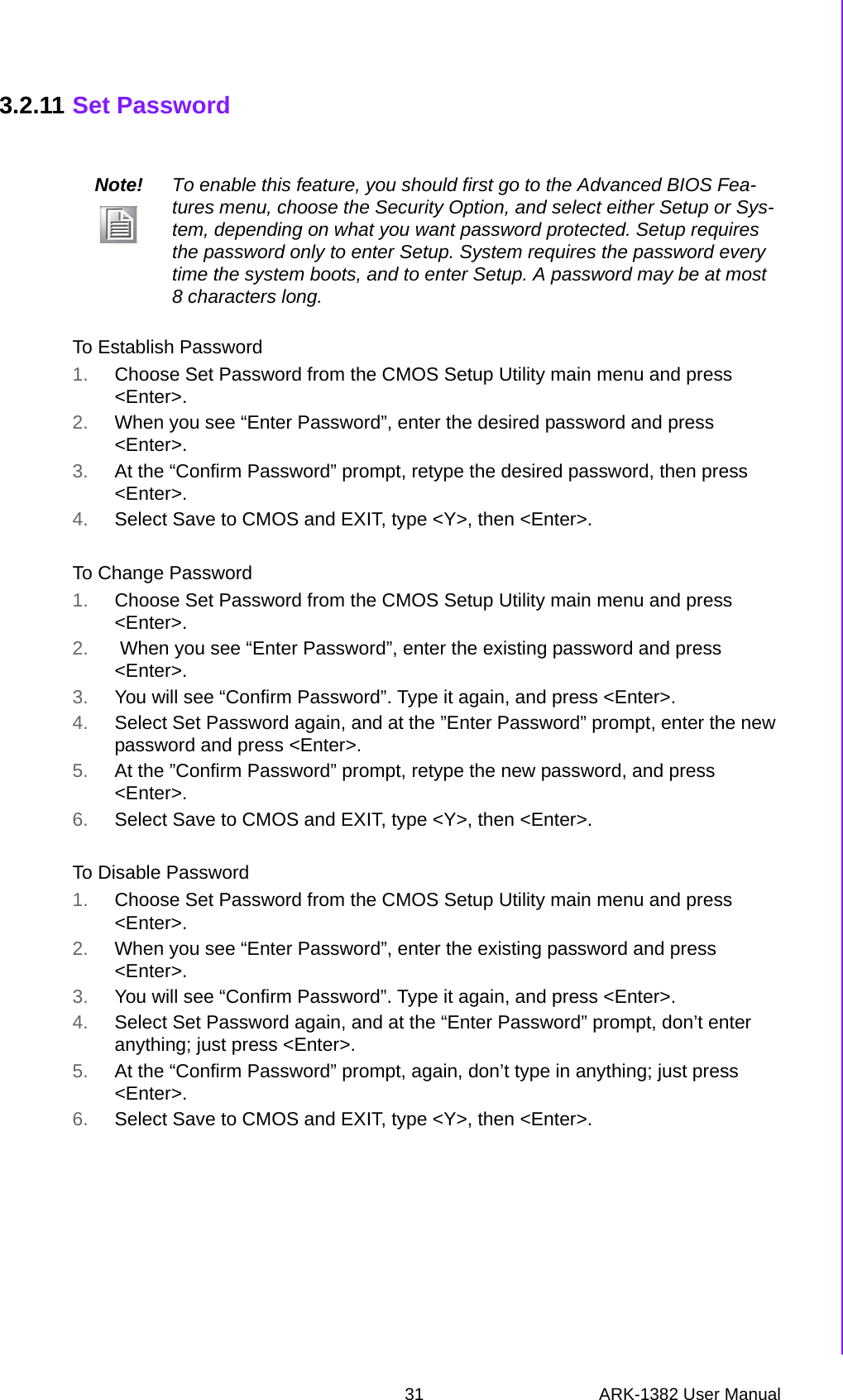
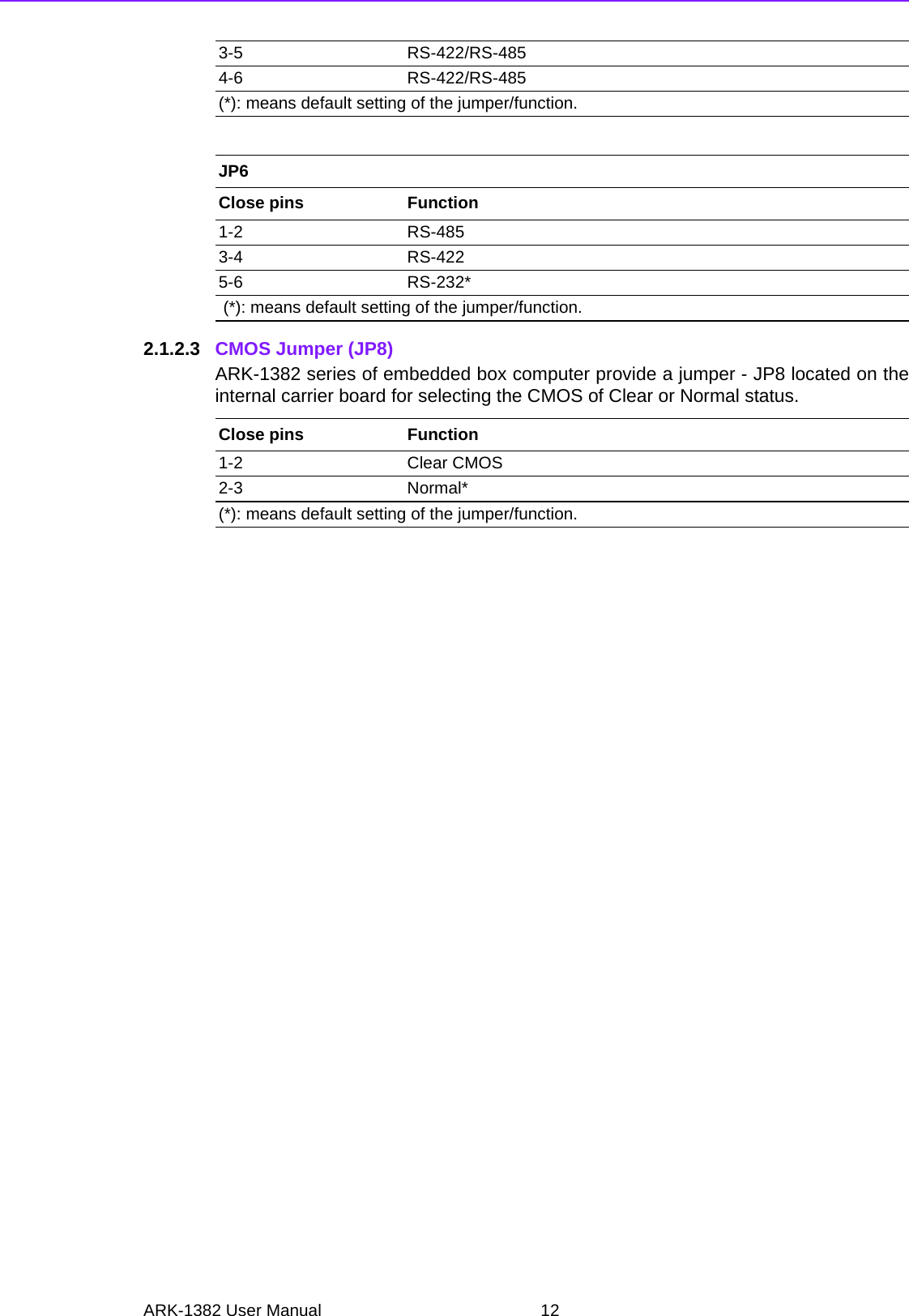
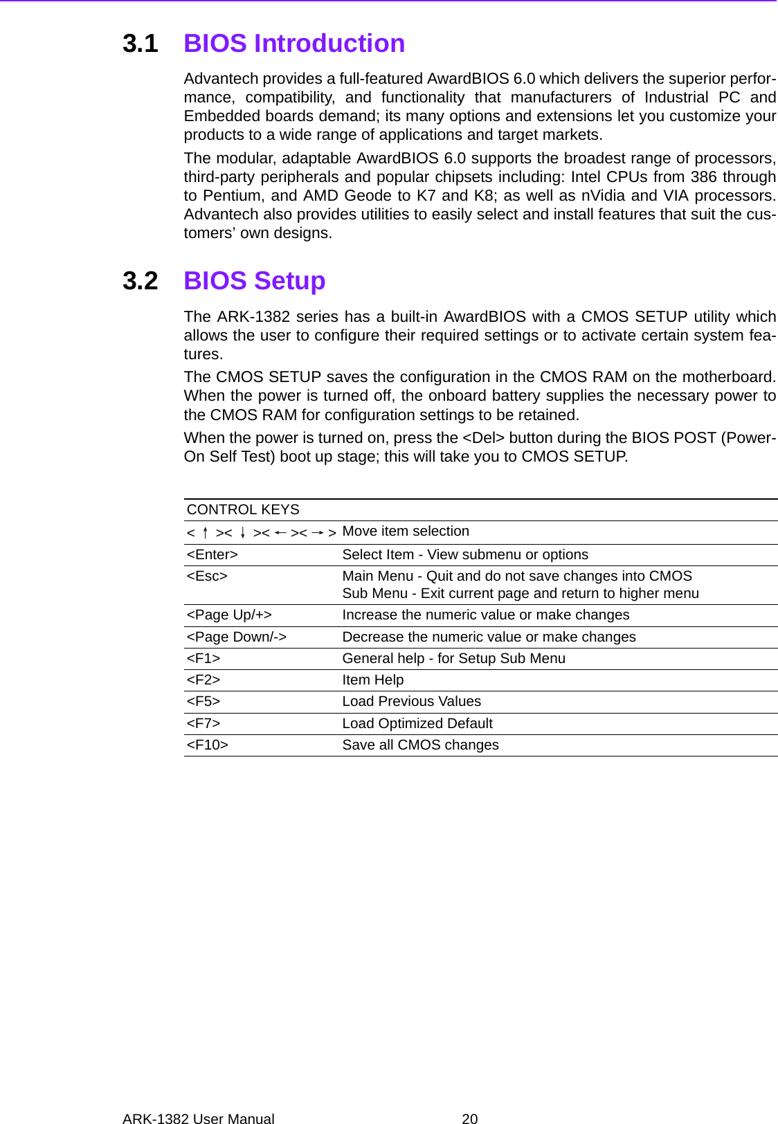
![11 ARK-1382 User ManualChapter 2 H/W Installation2.1.2 Jumper Setting 2.1.2.1 COM1 JumperARK-1382 series of embedded box computer provide a jumper - JP1 ~ JP3 locatedon the internal carrier board for COM1 selecting the RS-232, RS422 and RS485.2.1.2.2 COM2 JumperARK-1382 series of embedded box computer provide a jumper - JP1 ~ JP3 locatedon the internal carrier board for COM2 selecting the RS-232, RS422 and RS485.]JP1Close pins Function1-3 RS-232*2-4 RS-232*3-5 RS-422/RS-4854-6 RS422/RS-485(*): means default setting of the jumper/function.JP2Close pins Function1-3 RS-232*2-4 RS-232*3-5 RS-422/RS-4854-6 RS-422/RS-485(*): means default setting of the jumper/function.JP3Close pins Function1-2 RS-4853-4 RS-4225-6 RS-232* (*): means default setting of the jumper/function.JP4Close pins Function1-3 RS-232*2-4 RS-232*3-5 RS-422/RS-4854-6 RS422/RS-485(*): means default setting of the jumper/function.JP5Close pins Function1-3 RS-232*2-4 RS-232*](https://usermanual.wiki/Advantech-Co/ARK-1382/User-Guide-987498-Page-17.png)
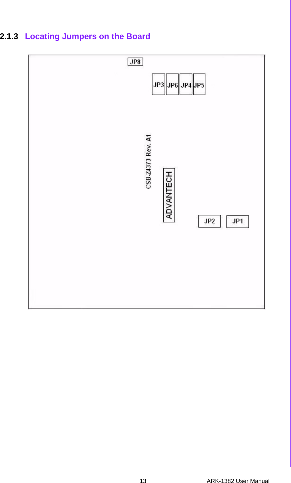
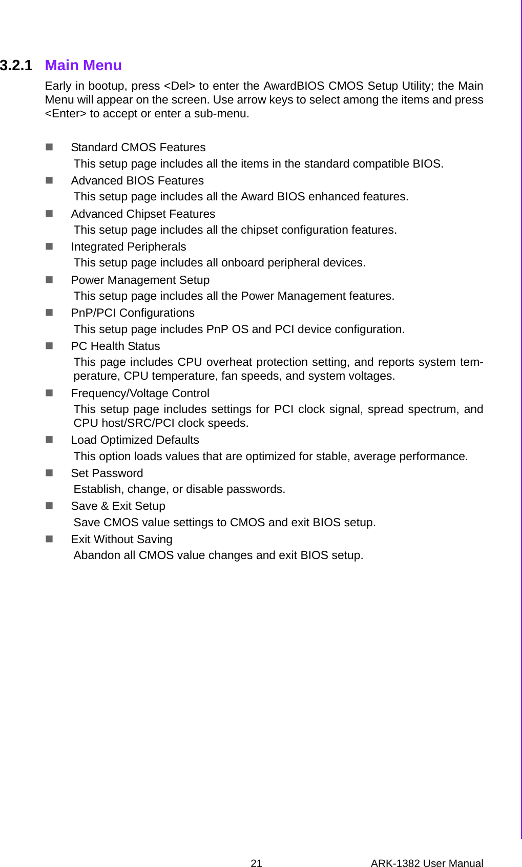
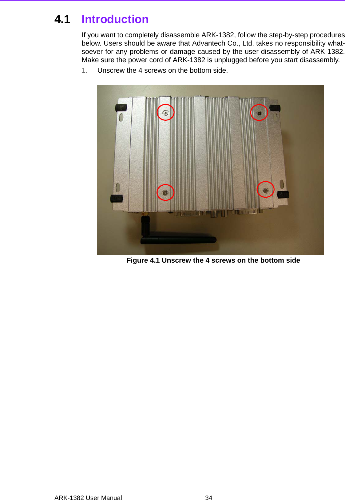
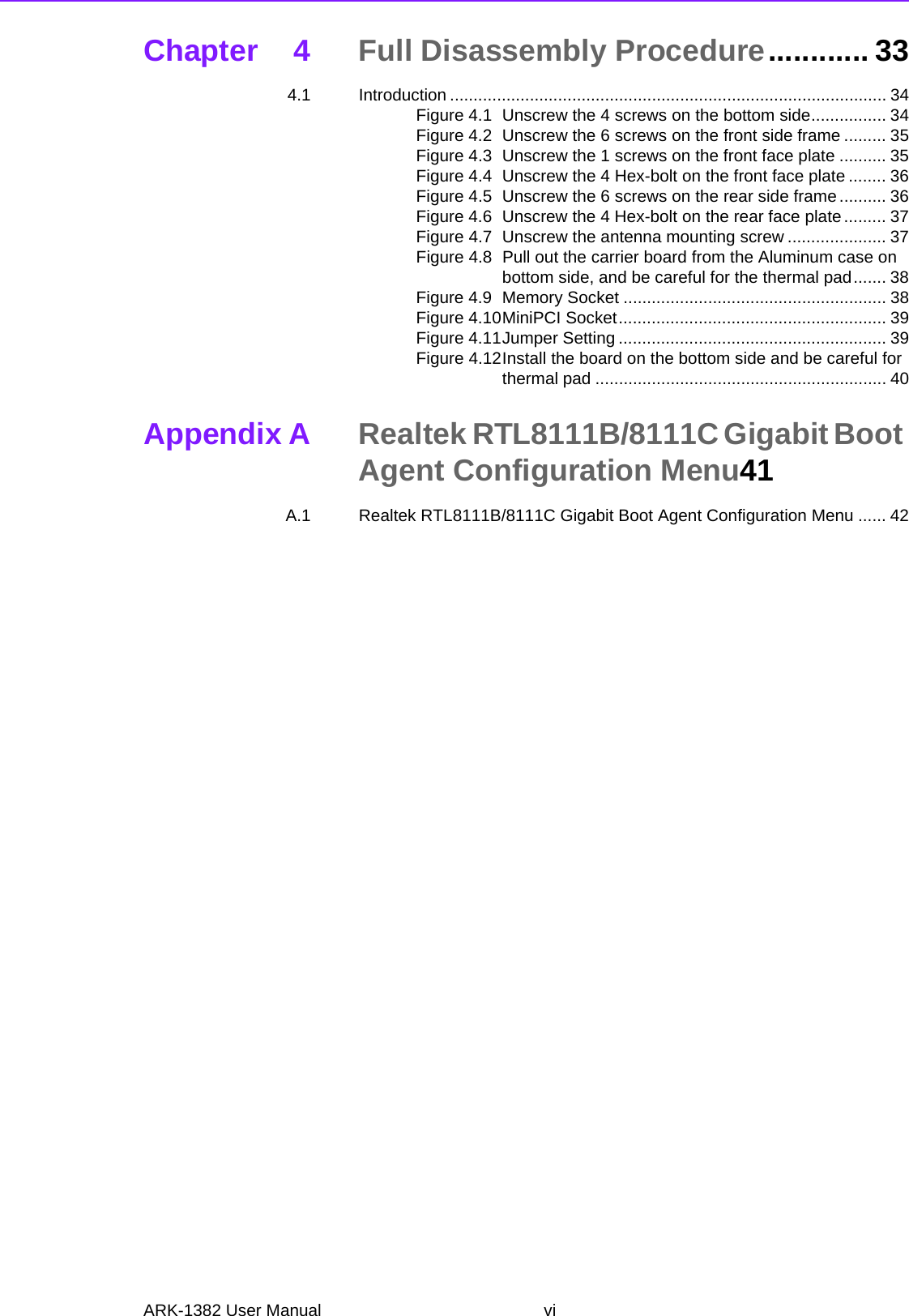
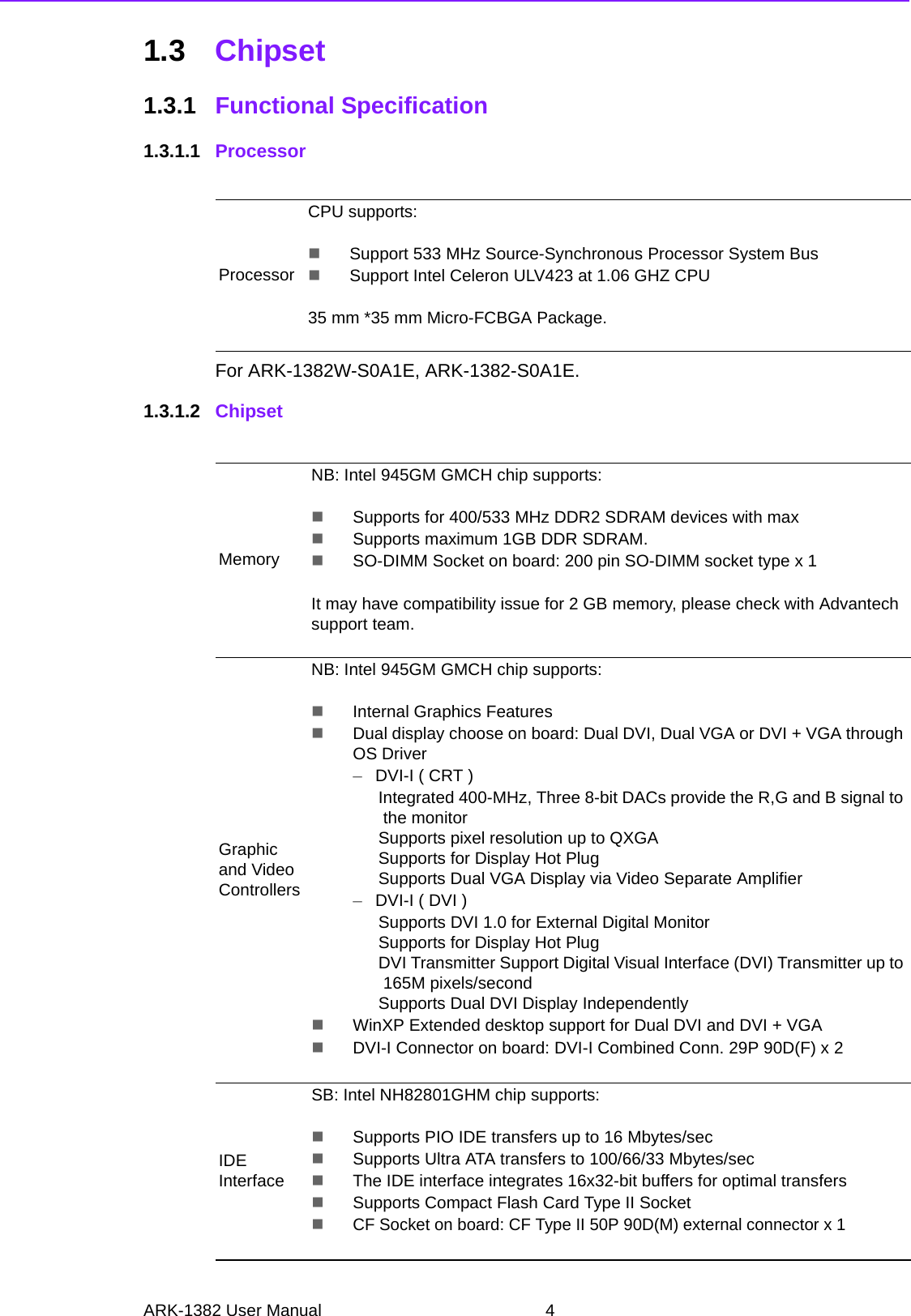
![23 ARK-1382 User ManualChapter 3 BIOS Operation3.2.3 Advanced BIOS FeaturesBlank Boot [Disabled] (* Advantech feature enhancement)When enabled, the system displays a blank screen during the BIOS POSTstage.POST Beep [Enabled] (* Advantech feature enhancement)When enabled, the system emits beep sounds during the BIOS POST stage.CPU FeatureThis item allows users to adjust CPU features, CPU ratio, VID. Thermal andspecial features like XD flag.Hard Disk Boot PriorityThis item allows users to select the boot sequence for system hard drivedevices - HDD, SCSI, RAID.USB Boot PriorityThis item allows user to select boot sequence for USB device Boot.Virus Warning [Disabled]This item allows users to choose or disable the virus warning feature for IDEHard Disk boot sector protection.Quick Power On Self Test [Enabled]This field speeds up the Power-On Self Test (POST) routine by skipping thesecond, third, and forth re-tests. Default setting is enabled.First / Second / Third / Other Boot DriveBoot Up NumLock Status [On]When enabled, the keyboard keypad boots up in number mode. When dis-abled, the keypad boots up in cursor control mode (arrow mode).Gate A20 Optio [Fast]This item enables the user to switch A20 control by port 92 or not.Typematic Rate SettingThis item enables users to enable or disable typematic action. When enabled,they can set the two typematic controls items. These fields control the speeds of:–Typematic Rate (Chars/Sec)This item controls the speed at which the system registers repeated key-strokes. The eight settings are 6, 8, 10, 12, 15, 20, 24 and 30.–First [USB Device]–Second [USB-CDROM]–Third [Hard Disk]–Other [Enabled]Hard Disk Select boot device priority by CF.USB Device Select boot device priority by USB Device.USB-FDD Select boot device priority by USB-FDD.USB-CDROM Select boot device priority by USB-CDROM.LAN Select boot device priority by LAN.Disabled Disable this boot function.](https://usermanual.wiki/Advantech-Co/ARK-1382/User-Guide-987498-Page-29.png)
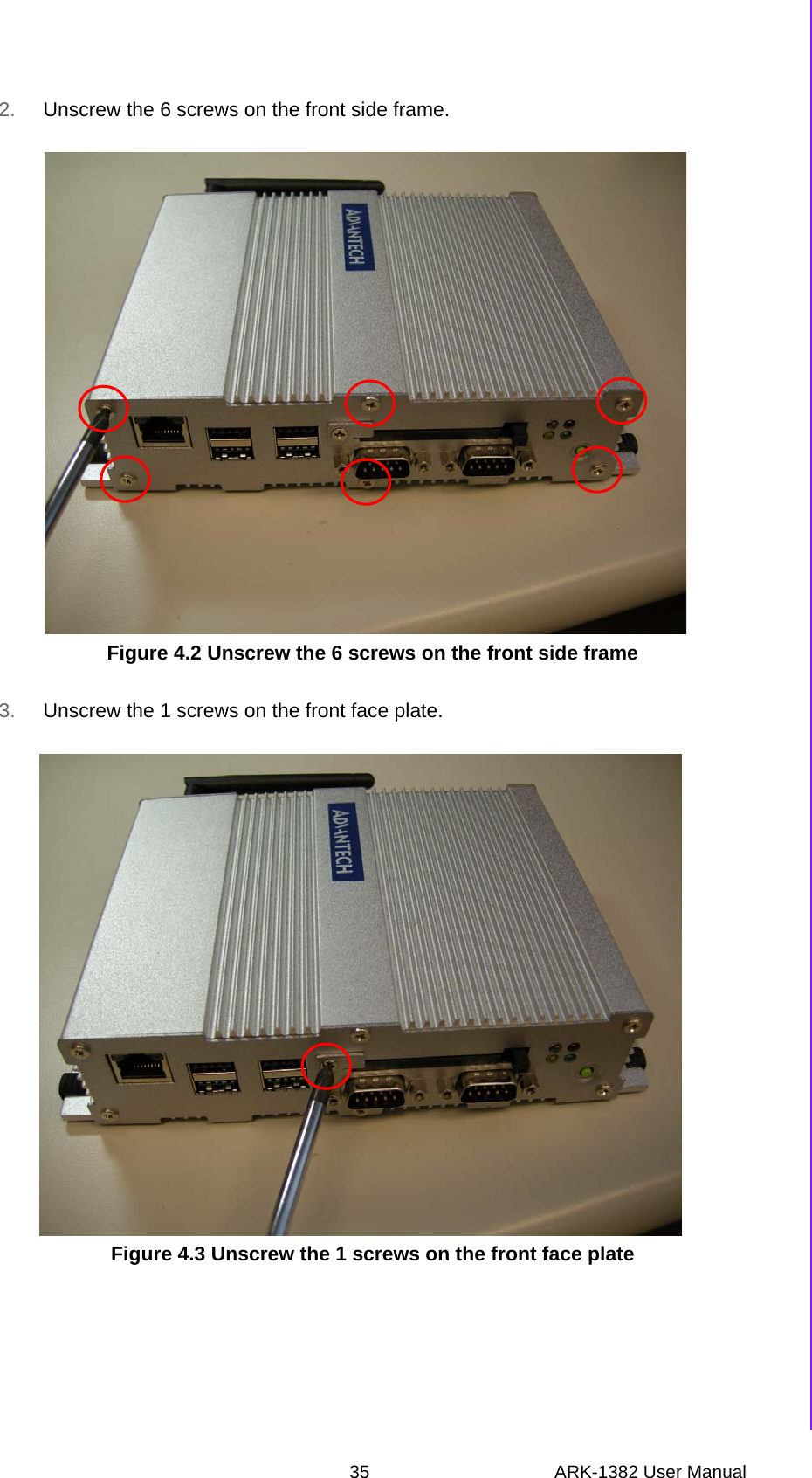
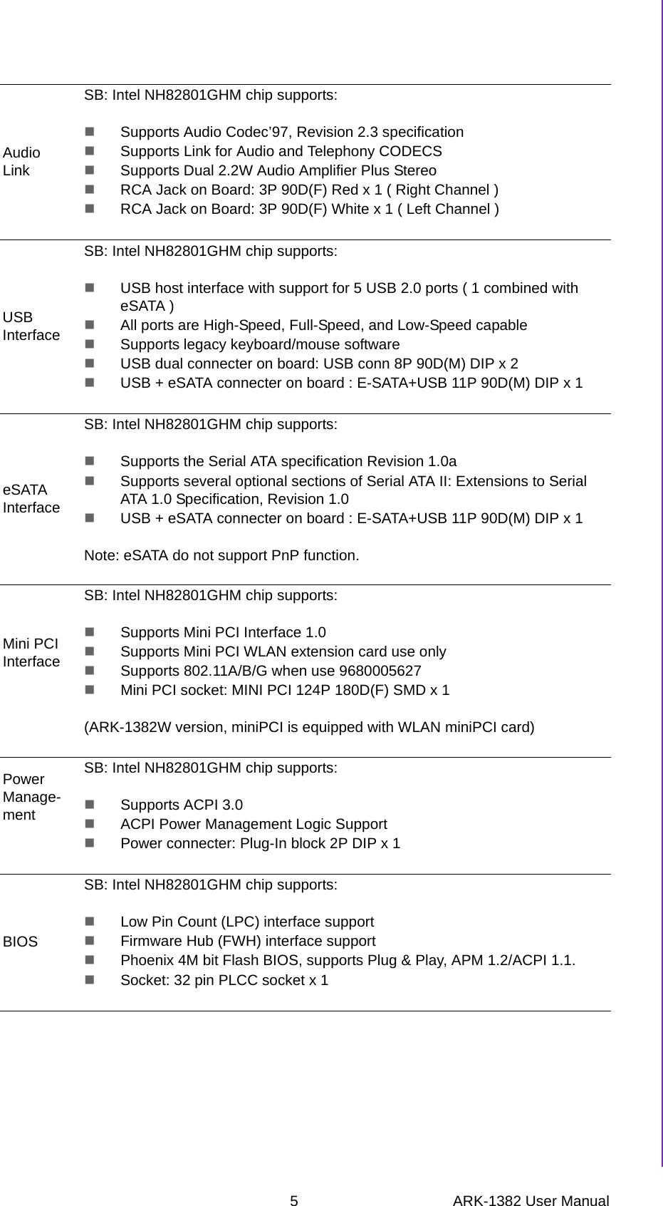
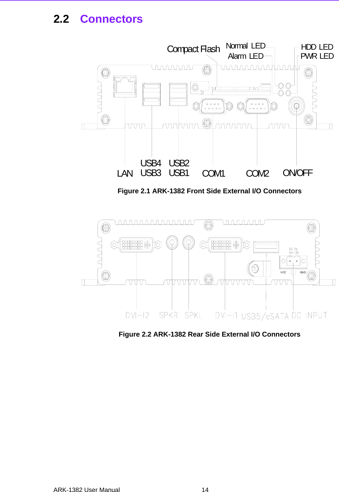
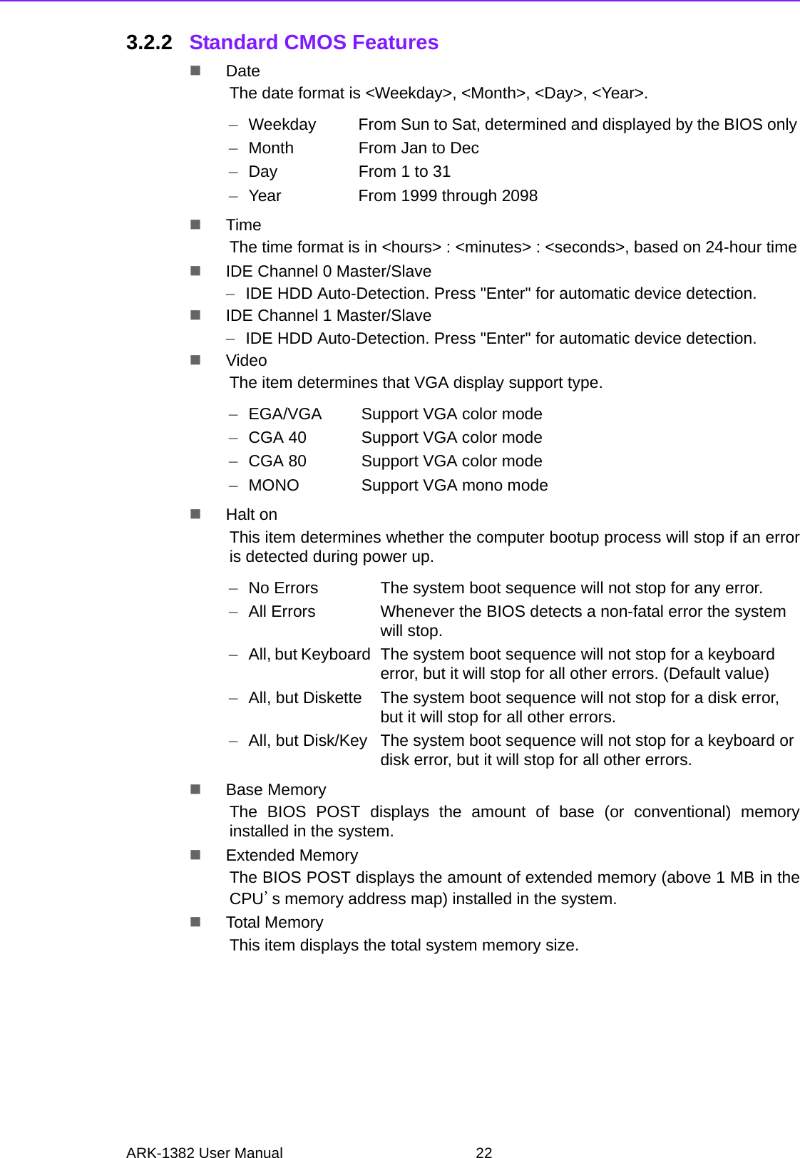
![ARK-1382 User Manual 24–Typematic Delay (Msec)This item sets the keypress delay before typematic repetition kicks in. Thefour delay options are 250, 500, 750 and 1000.Security Option [Setup]APIC Mode[Enabled]This item allows user to enabled of disabled “Advanced Programmable Inter-rupt Controller”. APIC is implemented in the motherboard and must be sup-ported by the operating system, and it extends the number of IRQ's available.MPS Version Control for OS [1.4]This item sets the system multiprocessor specification version.OS Select For DRAM > 64 M [Non-OS2]Select OS2 only if the system is running OS/2 with greater than 64 MB of RAMon the system.Full Screen Logo Show [Enabled]Shows full screen logo during POST stage; logo image can be customized.Small Logo (EPA) Show [Disable]Shows EPA logo during system POST stage.Summary Screen Show [Enabled]Shows system status on summary screen page.Note! These typematic settings apply to systems that communicate with the keyboard via BIOS. For Windows systems, typematic settings are con-trolled by keyboard driver settings in Windows Control Panel.–System System requires password both for bootup and for access to the Setup page.–Setup System requires password only for access to the Setup page, not for bootup. (Default value)](https://usermanual.wiki/Advantech-Co/ARK-1382/User-Guide-987498-Page-30.png)
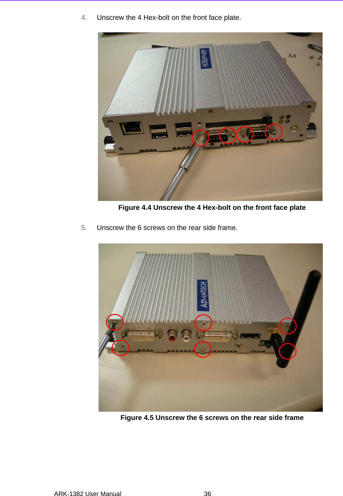
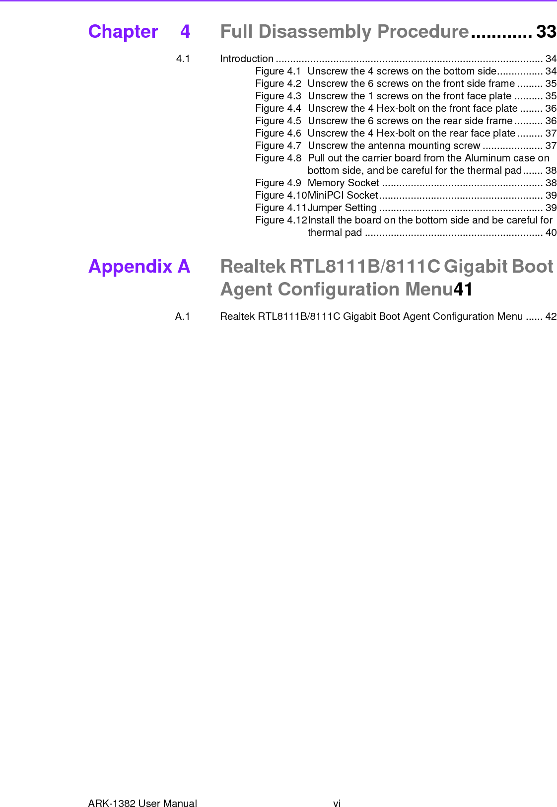
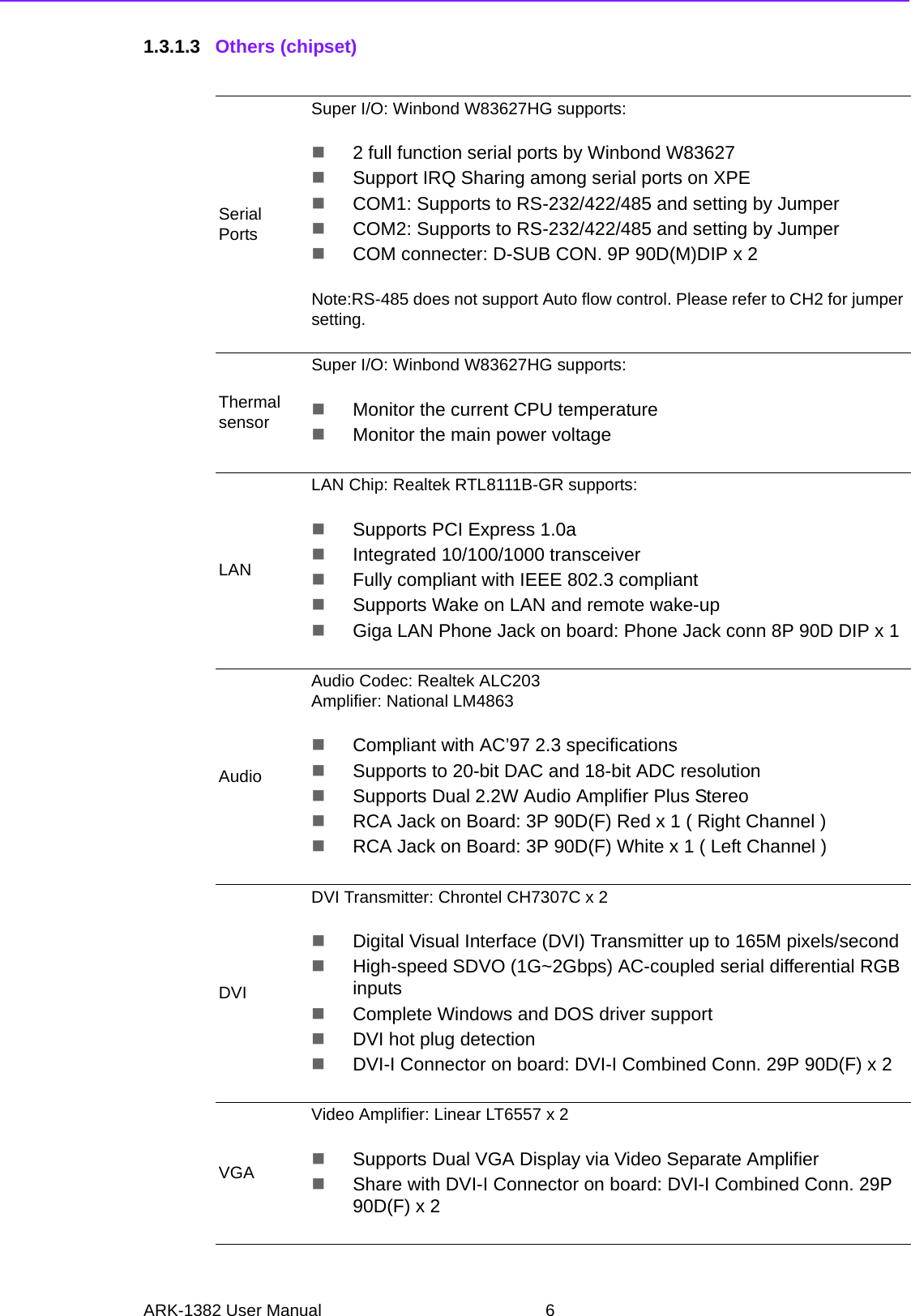
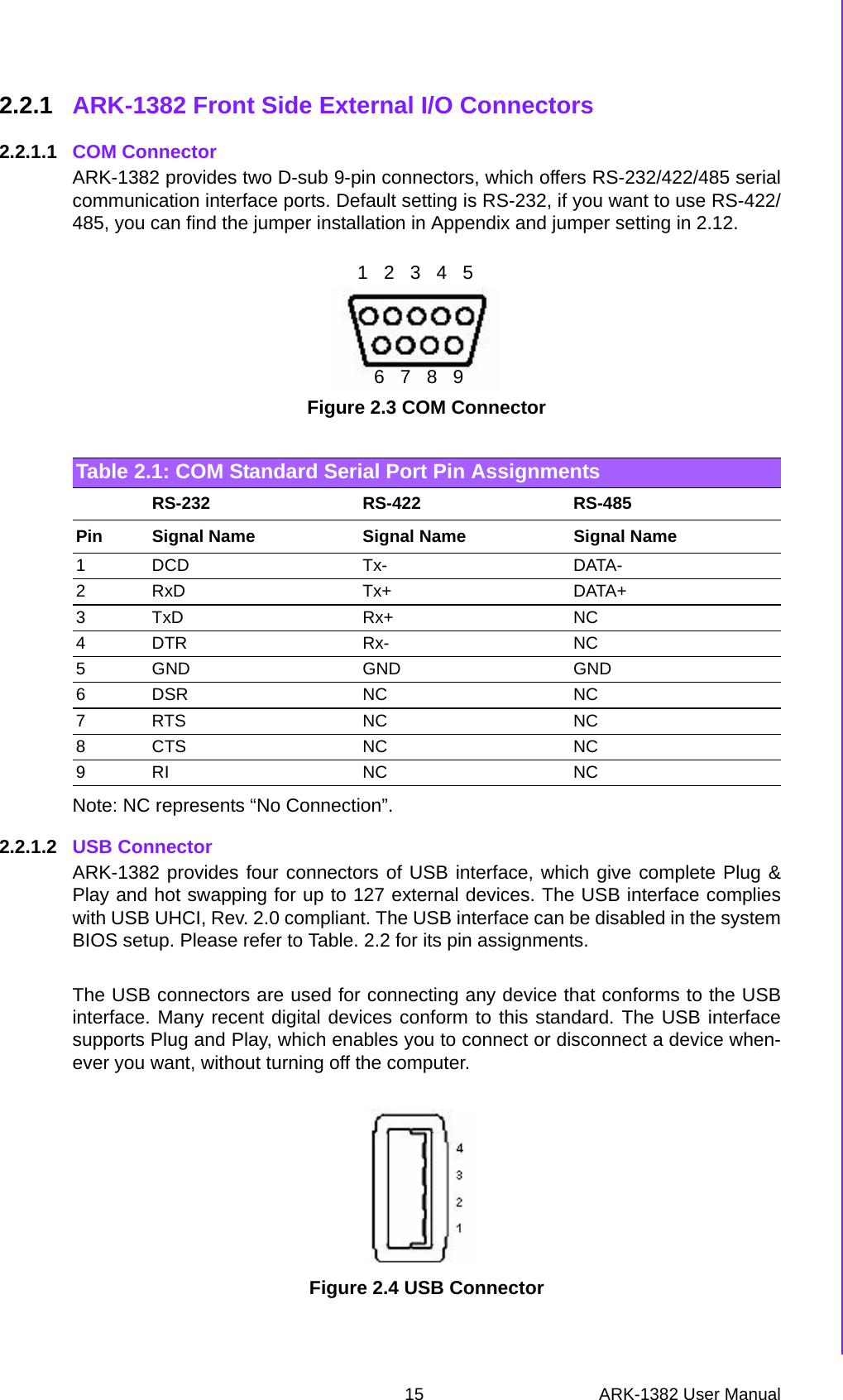
![25 ARK-1382 User ManualChapter 3 BIOS Operation3.2.4 Advanced Chipset FeaturesDRAM Timing Selectable [By SPD]This item enables users to set optimal timings for items 2 through to 5. The sys-tem default setting of “By SPD” ensures the system runs with stable and opti-mal performance.CAS Latency Time [Auto]This item enables users to set the timing delay in clock cycles before theSDRAM starts a read command after receiving it. DRAM RAS# to CAS# Delay [Auto]This item enables users to set the timing of the transition from RAS (RowAddress Strobe) to CAS (Column Address Strobe) as both rows and columnsare separately addressed shortly after DRAM is refreshed.DRAM RAS# Precharge [Auto]This item enables users to set the DRAM RAS# precharge timing. Systemdefault is set to “Auto” to reference the data from SPD ROM. Prechage delay (tRAS) [Auto]This item allows user to adjust memory precharge time.System Memory Frequency [Auto]This item allows user to adjust memory frequency to improvement perfor-mance.SLP_S4# Assertion Width [1 to 2 sec.]This item allows user to adjust SLP_S4# signal.This field indicates the mini-mum assertion width of the SLP_S4# signal to ensure that the DRAMs havebeen safely power-cycled.System BIOS Cacheable [Enabled]This item allows the system BIOS to be cached to allow faster execution andbetter performance.Video BIOS Cacheable [Disabled]This item allows the video BIOS to be cached to allow faster execution and bet-ter performance.Memory Hole At 15 M-16 M [Disabled]This item reserves 15 MB-16 MB memory address space to ISA expansioncards that specifically require the setting. Memory from 15 MB-16 MB will beunavailable to the system because only expansion cards can access memory inthis area.PEG/Onboard VGA Control [Auto]This item allows the user to select whether onboard graphics processor or thePCI Express card.On-Chip Frame Buffer Size [8 MB]This item allows the user to choose Frame Buffer Size. BIOS default value isset to 8 MB.Note! This “Advanced Chipset Features” screen controls the configuration of the board’s chipset; this page is developed to be chipset independent for fine-tuning system performance. It is strongly recommended that only technical users make changes to the default settings.](https://usermanual.wiki/Advantech-Co/ARK-1382/User-Guide-987498-Page-31.png)
![ARK-1382 User Manual 26DVMT Mode [ DVMT]This item allows the user to adjust Intel's Dynamic Video Memory Technology(DVMT).Bios provide three option to choose (DVMT, FIXED and Both).DVMT/FIXED Memory Size [128MB]This item allows the user to adjust DVMT/FIXED graphics memory size.Boot Display [VBIOS Default]This item allows the user to decide that display mode.3.2.5 Integrated PeripheralsOnChip IDE Device This item enables users to set the OnChip IDE device status, including enablingIDE devices and setting PIO and DMA access mode, plus some new chipsetsupport for SATA devices (Serial-ATA).–IDE HDD Block Mode [Enabled]This item allows the users to enable for automatic detection of optimal num-ber of block read/writes per sector the drive can support if IDE Hard Driversupports block mode–IDE DMA transfer access Mode [Enabled]This item allows the user to enable the DMA transfer access.–On-Chip Primary / Secondary PCI IDE [Enabled]This item allows the user to select the PIO or UDMA mode.–SATA Mode [IDE]The item allows the users to support IDE mode.–SATA Port Speed Settings [Disabled]This item allows the users to select SATA port speed.Onboard Device This item enables users to set the Onboard device status, including enablingUSB, AC97, MC97 and LAN devices.Super IO Device This item enables users to set the Super IO device status, including enablingFloppy, COM, LPT, IR and control for GPIO and Power Fail status.–Onboard Serial Port 1 [3F8/IRQ4]This item allows the user to change the COM 1 address and IRQ. BIOSdefault value suggest to .3F8/IRQ4.–Onboard Serial Port 2 [2F8/IRQ3]This item allows the user to chang13 the COM 2 address and IRQ. BIOSdefault value suggest to .2F8/IRQ3.–UART Mode Select [Normal]This item allows the selection for the mode of operation of the serial port.–Onboard Parallel Port [378/IRQ7]This item allows the user to change the parallel port address. BIOS defaultvalue is set to .378/IRQ7..Note! This “Integrated Peripherals” screen controls the configuration of the board’s chipset, including controls for: IDE, ATA, SATA, USB, AC97, MC97 and Super IO and sensor devices; this page is developed to be chipset independent.](https://usermanual.wiki/Advantech-Co/ARK-1382/User-Guide-987498-Page-32.png)
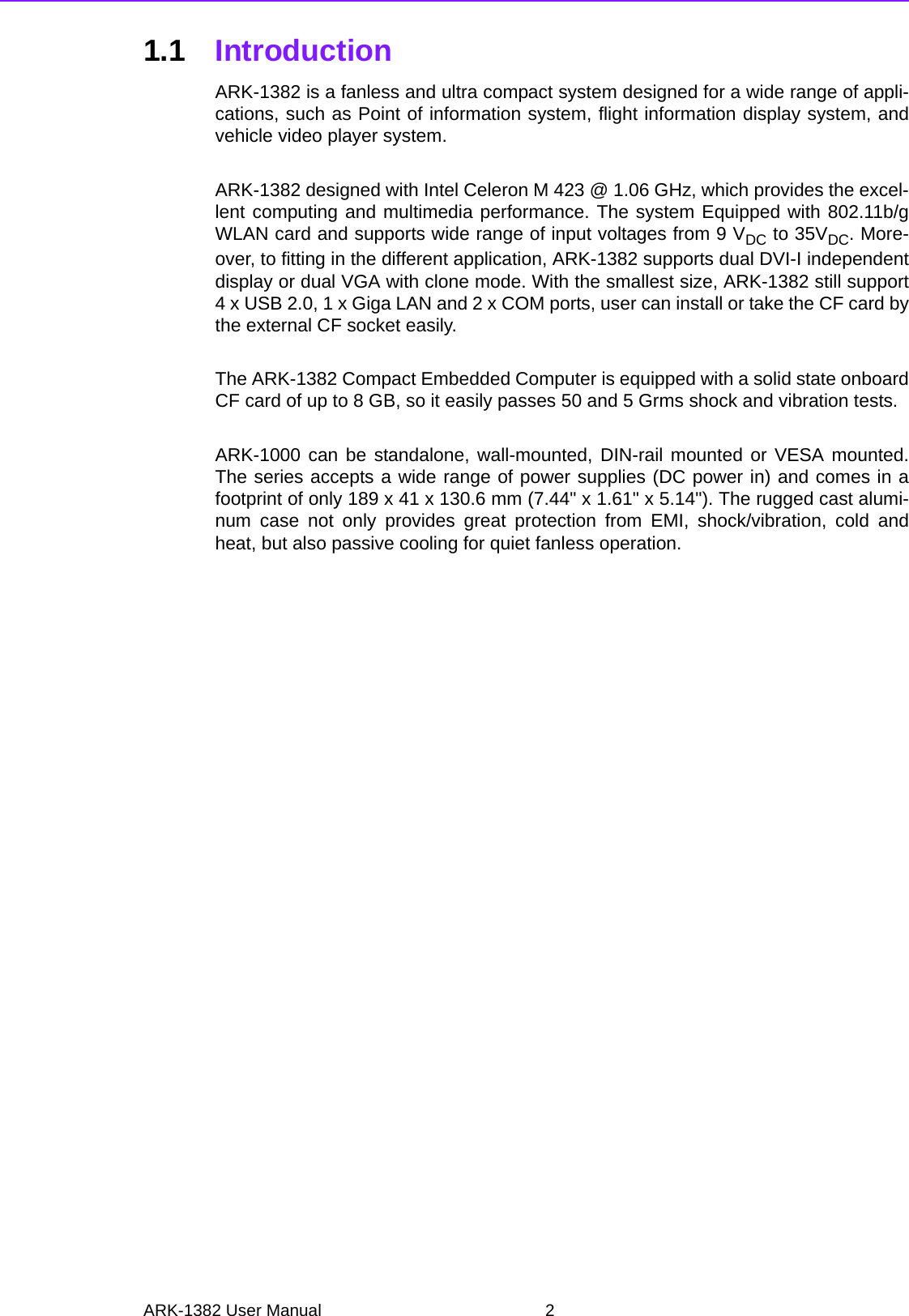
![27 ARK-1382 User ManualChapter 3 BIOS Operation–Parallel Port Mode [SPP]This item allows the user to change the parallel port mode. The user canchoose .SPP., .EPP., .±ECP. and .ECP+EPP.; SPP (Standard Parallel Port );ECP (Extended Capabilities Port); and EPP (Enhanced Parallel Port). TheBIOS default value is set to .Normal..–EPP Mode Select [EPP1.7]This item allows the user to change the EPP Mode for the parallel port. TheBIOS default value is set to .EPP1.7..–ECP Mode Use DMA [3]This item allows the user to change the DMA channel for the parallel port.The BIOS default value is set to 3.PWRON After PWR-Fail [Off]This item allows user to select system power status after power loss.3.2.6 Power Management SetupACPI Function [Enabled]This item defines the ACPI (Advanced Configuration and Power Interface) fea-ture that makes hardware status information available to the operating system,and communicates PC and system device information for improving powermanagement.ACPI Suspend Type [S1 (POS)]This item allows users to select sleep state when the system is in suspendmode. –S1(POS) Suspend mode is equivalent to a software power down.–S3(STR) The system shuts down with the exception of a refreshcurrent to the system memory.–S1 & S3 This item is support two mode be selection by software.Run VGA BIOS if S3 Resume [Auto]This item allows the system to reinitialize the VGA BIOS after the system hasresumed from ACPI S3 mode.Power Management Option [User Define]This item allows user to select system power saving mode.–Min Saving Minimum power management. Suspend Mode=1 hr.–Max Saving Maximum power management. Suspend Mode=1 min.–User Define Allows user to set each mode individually. Suspend Mode= Disabled or 1 min ~1 hr.Video Off Method [DPMS]This item allows users to determine the manner in which the monitor is blanked.–V/H SYNC+Blank This option will cause the system to turn off vertical and horizontal synchronization ports and write blanks to the video buffer.–Blank Screen This option only writes blanks to the video buffer.–DPMS Initial displays power management signaling. Note! This “Power Management Setup” screen configures the system to most effectively save energy while operating in a manner consistent with your computer use.](https://usermanual.wiki/Advantech-Co/ARK-1382/User-Guide-987498-Page-33.png)
![ARK-1382 User Manual 28Video Off In Suspend [Yes]This item allows users to turn off video when entering suspend mode.Suspend Type [Stop Grant]This item allows users to determine the suspend type.Modem use IRQ [3]This item allows users to determine which IRQ the MODEM can use.Suspend Mode [Disabled]Shows the time of system inactivity before all devices except the CPU will beshut off.HDD Power Down Mode [Disabled]Shows the time of system inactivity before the hard disk drive will be powereddown.Soft-Off by PWR-BTTN [Instant-Off]This item allows users to define power button functions.–Instant-Off Press power button to power-off instantly.–Delay 4 Sec Press power button for 4 seconds to power-off.Energy Lake Function[Disabled]Wake-Up by PCI card [Enabled]This item allows users to permit PCI cards to wake up the system from suspendmode.Power On by Ring [Enabled]This item allows users to permit the system to power-on from a modem ring.USB KB Wake-Up From S3 [Disabled]This item allows users to use a USB keyboard to wake up the system frompower saving mode.Resume by Alarm [Disabled]This item allows users to power on the system at a specified date and/or time.–Disabled Disable this function.–Enabled Enable alarm function to power on system–Data (of month) Alarm1-31–Time (HH:MM:SS) Alarm(0-23) : (0-59) : 0-59)](https://usermanual.wiki/Advantech-Co/ARK-1382/User-Guide-987498-Page-34.png)
![29 ARK-1382 User ManualChapter 3 BIOS Operation3.2.7 PnP/PCI ConfigurationsInit Display First [Onboard]This item allow user to select initial display mode, optional item include PCI slotand Onboard.Reset Configuration Data [Disabled]This item allows users to clear any PnP configuration data stored in the BIOS.Resources Controlled By [Auto (ESCD)]–IRQ ResourcesThis item allows you respectively assign an interruptive type for IRQ-3, 4, 5,7, 9, 10, 11, 12, 14, and 15.PCI VGA Palette Snoop [Disabled]The item is designed to solve problems caused by some non-standard VGAcards. A built-in VGA system does not need this function.INT Pin 1~8 Assignment [Auto]The interrupt request (IRQ) line assigned to a device connected to the PCIinterface on your system.Maximum payload Size [128]The item allows user to adjust maximum TLP (Transaction Layer Packet) pay-load size.3.2.8 PC Health StatusShutdown Temperature [Disabled]This item allow user to set the temperature to notify the ACPI OS to shutdownthe system.Current System/CPU Temp [Show Only]This item displays current system and CPU temperature.2.5 V / 3.3 V / 5 V / 12 V and VCore [Show Only]This item displays current CPU and system Voltage.Note! This “PnP/PCI Configurations” screen is setting up the IRQ and DMA (both PnP and PCI bus assignments.) Note! This “PC Health Status” screen reports the Thermal, FAN and Voltage status of the board. This page is developed to be chipset independent.](https://usermanual.wiki/Advantech-Co/ARK-1382/User-Guide-987498-Page-35.png)
![ARK-1382 User Manual 303.2.9 Frequency/Voltage ControlAuto Detect PCI Clk [Enabled]This item enables users to set the PCI Clock by system automatic detection orby manual.Spread Spectrum [Enabled]This item enables users to set the spread spectrum modulation.3.2.10 Load Optimized DefaultsNote! NOTE: This “Frequency/Voltage Control” option controls the CPU Host and PCI frequency, this page is developed by CPU and Chipset inde-pendent, some items will show up when you install a processor which supports this function.Note! Load Optimized Defaults loads the default system values directly from ROM. If the stored record created by the Setup program should ever become corrupted (and therefore unusable). These defaults will load automatically when you turn the ARK-1382 Series system on.](https://usermanual.wiki/Advantech-Co/ARK-1382/User-Guide-987498-Page-36.png)