Advantech Co ARK-3384 EBPC, PM-1.4G User Manual ARK 3384 User Manual
Advantech Co Ltd EBPC, PM-1.4G ARK 3384 User Manual
UserManual.wiki
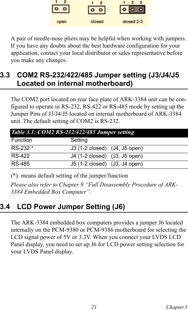
>
Advantech Co
>
ARK-3384 User Manual
>
User Manual 1
Contents
1.
User Manual 1
2.
User Manual 2
User Manual 1
Navigation menu
Upload a User Manual
Namespaces
Wiki Guide
HTML
PDF
Info
Views
User Manual
Discussion / Help
Navigation


![xv4.7.15 Time (hh:mm:ss) Alarm................................................ 484.7.16 Primary IDE 0/ 1 and Secondary IDE 0 / 1 .................. 484.7.17 FDD, COM, LPT PORT............................................... 494.7.18 PCI PIRQ [A-D]# ......................................................... 494.7.19 PWRON After PWR-Fail ............................................. 494.8 PnP/PCI Configurations .................................................. 494.8.1 Reset Configuration Data.............................................. 49Figure 4.12 PnP/PCI configurations screen ............... 504.8.2 Resources controlled by................................................ 504.8.3 IRQ Resources .............................................................. 504.8.4 PCI/VGA Palette Snoop ............................................... 504.9 Frequency/Voltage Control............................................. 514.9.1 Auto Detect PCI CLK................................................... 514.9.2 Spread Spectrum........................................................... 514.9.3 CPU Host/3V66/PCI Clock .......................................... 51Figure 4.13 Frequency/Voltage Control .................... 514.10 Load Optimized Defaults ................................................ 524.11 Set Password ................................................................... 524.12 Save & Exit Setup ........................................................... 524.13 Exit Without Saving........................................................ 52Chapter 5 PCI SVGA/LCD Setup ..................................545.1 Introduction ..................................................................... 545.1.1 CMOS setting for Boot Display type............................ 54Figure 5.1 Advanced Chipset features screen.......... 54Figure 5.2 Boot Display Selection ........................... 555.1.2 Dual Independent Display ............................................ 55Figure 5.3 Intel® 82852/82855 GM/GME Graphics Controller Properties – Devices ........... 56Figure 5.4 Intel® 82852/82855 GM/GME Graphics Controller Properties – Extended Desktop Settings................................................. 565.2 Installation of the SVGA Driver ..................................... 575.2.1 Installation for Windows 2000/XP ............................... 57Figure 5.5 CD Directory “2.VGA” .......................... 57Figure 5.6 Intel® Extreme Chipset Graphics Driver Software Install Wizard ....................... 58Figure 5.7 Intel® Extreme Graphics Driver Setup .. 58Figure 5.8 InstallShield® Wizard Complete............ 595.3 Further information ......................................................... 59Chapter 6 Audio Setup.....................................................626.1 Introduction ..................................................................... 626.2 Driver installation............................................................ 626.2.1 Before you begin........................................................... 626.2.2 Windows 2000/XP drivers............................................ 62](https://usermanual.wiki/Advantech-Co/ARK-3384.User-Manual-1/User-Guide-782264-Page-15.png)