Advantech Co ARK-3384 EBPC, PM-1.4G User Manual ARK 3384 User Manual
Advantech Co Ltd EBPC, PM-1.4G ARK 3384 User Manual
UserManual.wiki
>
Advantech Co
>
ARK-3384 User Manual
>
User Manual 2
Contents
1.
User Manual 1
2.
User Manual 2
User Manual 2
Navigation menu
Upload a User Manual
Namespaces
Wiki Guide
HTML
PDF
Info
Views
User Manual
Discussion / Help
Navigation
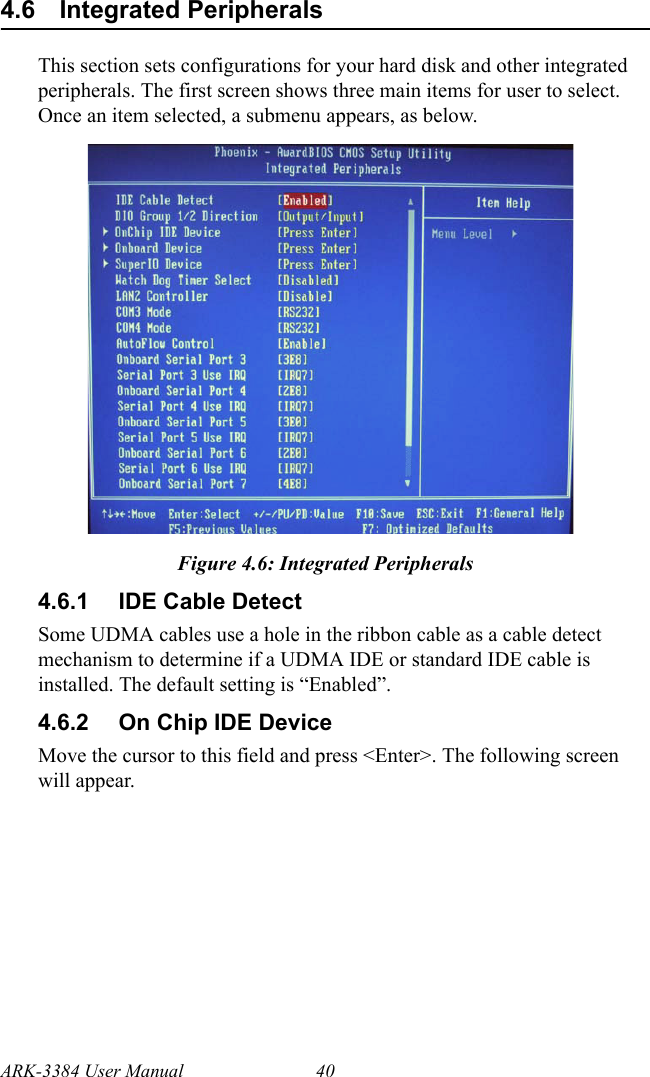
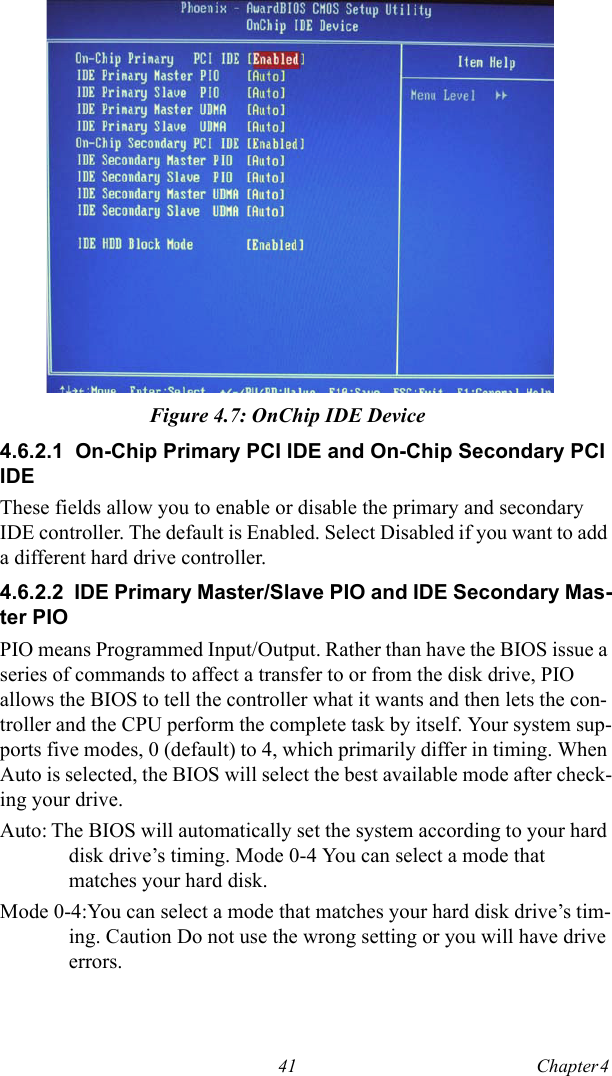
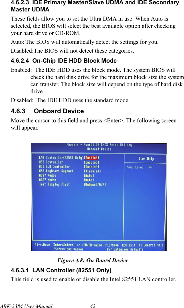
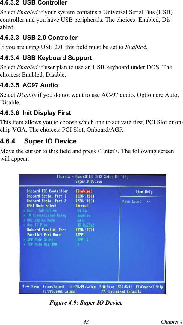
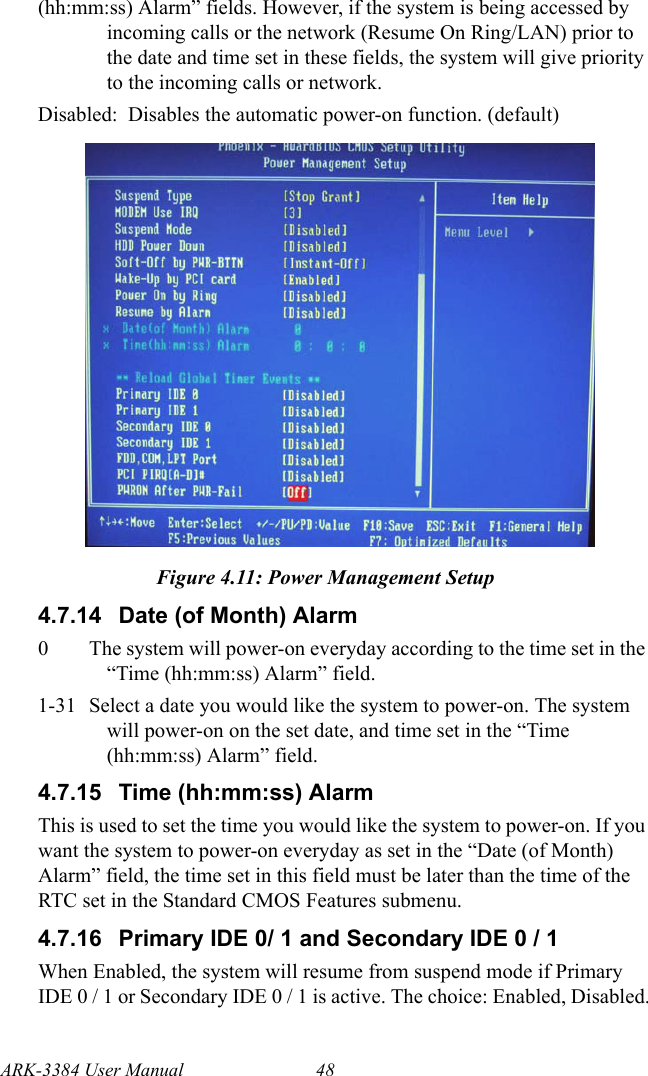
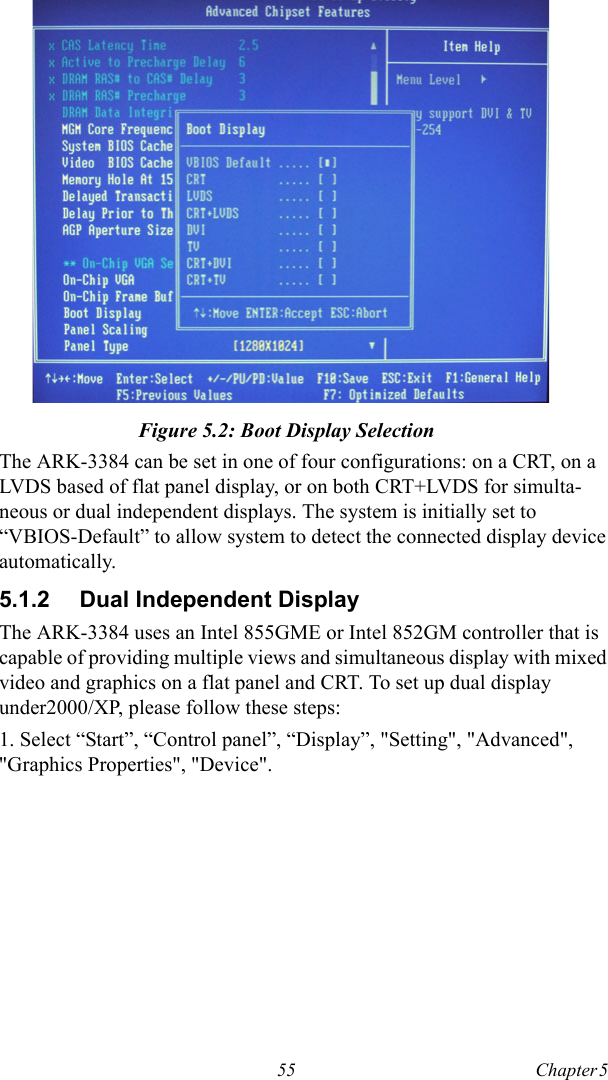
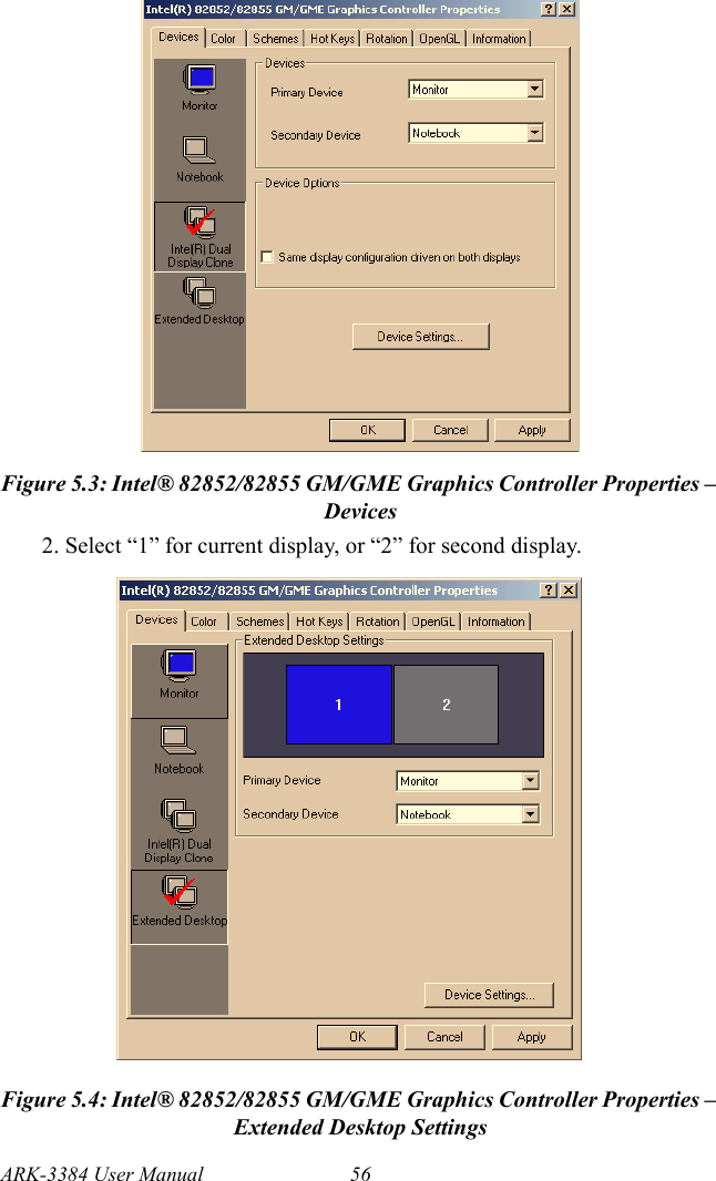
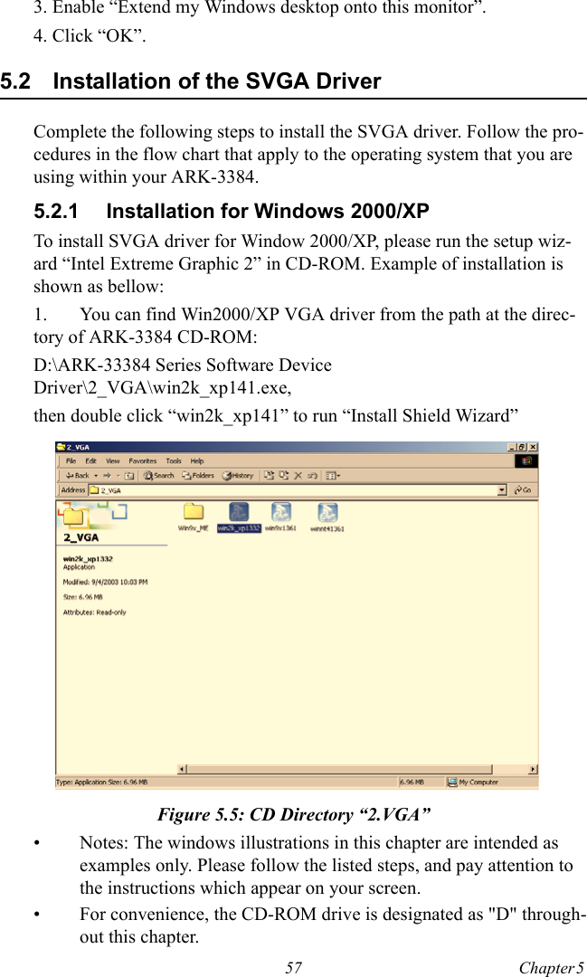
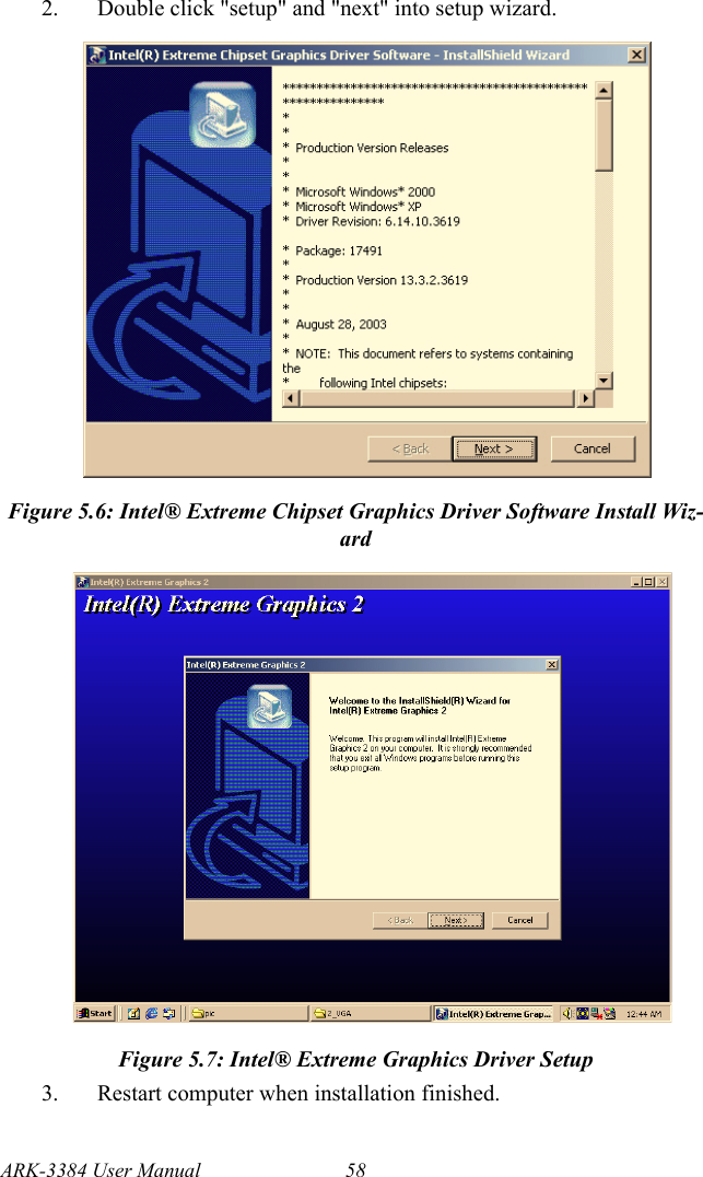
![49 Chapter 4 4.7.17 FDD, COM, LPT PORTWhen Enabled, the system will resume from suspend mode if FDD, COM port, or LPT port is active. The choice: Enabled, Disabled.4.7.18 PCI PIRQ [A-D]#When Enabled, the system will resume from suspend mode if interrupt occurs. The choice: Enabled, Disabled.4.7.19 PWRON After PWR-FailOff When power returns after an AC power failure, the system’s power is off. You must press the Power button to power-on the system.On When power returns after an AC power failure, the system will automatically power-onFormer-StsWhen power returns after an AC power failure, the system will return to the state where you left off before power failure occurs. If the system’s power is off when AC power failure occurs, it will remain off when power returns. If the system’s power is on when AC power failure occurs, the system will power on when power returns.4.8 PnP/PCI ConfigurationsThis section shows how to configure the PCI bus system. It covers some very technical items and it is strongly recommended that only experi-enced users should make any changes to the default settings.4.8.1 Reset Configuration DataDefault is Disable. Select Enable to reset Extended System Configuration Data (ESCD) if you have installed a new add-on and system configura-tion has caused such a conflict that OS cannot boot.Enabled: The BIOS will reset the Extended System Configuration Data (ESCD) once automatically. It will then recreate a new set of configuration data.Disabled: The BIOS will not reset the configuration data.](https://usermanual.wiki/Advantech-Co/ARK-3384.User-Manual-2/User-Guide-782265-Page-11.png)