Advantech Co ARK-3384 EBPC, PM-1.4G User Manual ARK 3384 User Manual
Advantech Co Ltd EBPC, PM-1.4G ARK 3384 User Manual
Contents
- 1. User Manual 1
- 2. User Manual 2
User Manual 2
39 Chapter 4
4.5.15 On-Chip Frame Buffer Size
The default setting is 32MB. The options available include 1MB, 4MB,
8MB and 16MB.
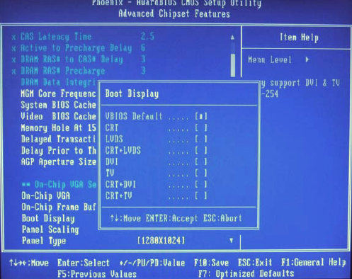
4.5.16 Boot Display
The default setting is VBIOS Default to allow system to detect the con-
nected display device automatically. The options available include
VBIOS-Default, CRT, LVDS, CRT+LVDS.
Figure 4.5: Boot Display
4.5.17 Panel Scaling
The default setting is Auto. The options available include On and Off.
4.5.18 Panel Type
These fields allow you to select the resolution of LCD Panel type. The
resolution values for these ports are:
640 x 480
800 x 600
1024 x 768
1280 x 1024
1600 x 1200
The default setting is 1280x1024
ARK-3384 User Manual 40
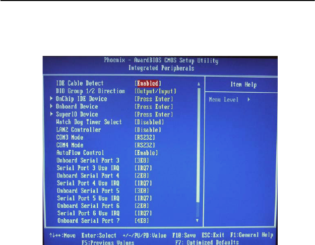
4.6 Integrated Peripherals
This section sets configurations for your hard disk and other integrated
peripherals. The first screen shows three main items for user to select.
Once an item selected, a submenu appears, as below.
Figure 4.6: Integrated Peripherals
4.6.1 IDE Cable Detect
Some UDMA cables use a hole in the ribbon cable as a cable detect
mechanism to determine if a UDMA IDE or standard IDE cable is
installed. The default setting is “Enabled”.
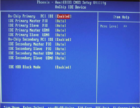
4.6.2 On Chip IDE Device
Move the cursor to this field and press <Enter>. The following screen
will appear.
41 Chapter 4
Figure 4.7: OnChip IDE Device
4.6.2.1 On-Chip Primary PCI IDE and On-Chip Secondary PCI
IDE
These fields allow you to enable or disable the primary and secondary
IDE controller. The default is Enabled. Select Disabled if you want to add
a different hard drive controller.
4.6.2.2 IDE Primary Master/Slave PIO and IDE Secondary Mas-
ter PIO
PIO means Programmed Input/Output. Rather than have the BIOS issue a
series of commands to affect a transfer to or from the disk drive, PIO
allows the BIOS to tell the controller what it wants and then lets the con-
troller and the CPU perform the complete task by itself. Your system sup-
ports five modes, 0 (default) to 4, which primarily differ in timing. When
Auto is selected, the BIOS will select the best available mode after check-
ing your drive.
Auto: The BIOS will automatically set the system according to your hard
disk drive’s timing. Mode 0-4 You can select a mode that
matches your hard disk.
Mode 0-4:You can select a mode that matches your hard disk drive’s tim-
ing. Caution Do not use the wrong setting or you will have drive
errors.
ARK-3384 User Manual 42
4.6.2.3 IDE Primary Master/Slave UDMA and IDE Secondary
Master UDMA
These fields allow you to set the Ultra DMA in use. When Auto is
selected, the BIOS will select the best available option after checking
your hard drive or CD-ROM.
Auto: The BIOS will automatically detect the settings for you.
Disabled:The BIOS will not detect these categories.
4.6.2.4 On-Chip IDE HDD Block Mode
Enabled: The IDE HDD uses the block mode. The system BIOS will
check the hard disk drive for the maximum block size the system
can transfer. The block size will depend on the type of hard disk
drive.
Disabled: The IDE HDD uses the standard mode.
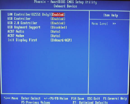
4.6.3 Onboard Device
Move the cursor to this field and press <Enter>. The following screen
will appear.
Figure 4.8: On Board Device
4.6.3.1 LAN Controller (82551 Only)
This field is used to enable or disable the Intel 82551 LAN controller.
43 Chapter 4
4.6.3.2 USB Controller
Select Enabled if your system contains a Universal Serial Bus (USB)
controller and you have USB peripherals. The choices: Enabled, Dis-
abled.
4.6.3.3 USB 2.0 Controller
If you are using USB 2.0, this field must be set to Enabled.
4.6.3.4 USB Keyboard Support
Select Enabled if user plan to use an USB keyboard under DOS. The
choices: Enabled, Disable.
4.6.3.5 AC97 Audio
Select Disable if you do not want to use AC-97 audio. Option are Auto,
Disable.
4.6.3.6 Init Display First
This item allows you to choose which one to activate first, PCI Slot or on-
chip VGA. The choices: PCI Slot, Onboard/AGP.
4.6.4 Super IO Device
Move the cursor to this field and press <Enter>. The following screen
will appear.
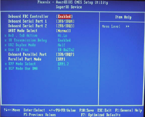
Figure 4.9: Super IO Device
ARK-3384 User Manual 44
The screen shown above, which list all the fields available in the Super IO
Device submenu for ease of reference in this manual. In the actual CMOS
setup, you have to use the scroll bar to view the fields. The settings on the
screen are for reference only. Your version may not be identical to this
one.
4.6.4.1 Onboard FDC Controller
When enabled, this field allows you to connect your floppy disk drives to
the onboard floppy disk drive connector instead of a separate controller
card. If you want to use a different controller card to connect the floppy
disk drives, set this field to Disabled. Note: ARK-3384 series embedded
box computer does not support interface connection.
4.6.4.2 Onboard Serial Port 1
You can disable the COM1 serial port by selecting “Disabled”, select the
“Auto” to allow the BIOS to arrange a suitable resource value for your
COM1 device connection automatically, or you can select the resource of
IRQ/IO Address combination for your COM 1 serial port device connec-
tion. The setup value options are:
Disabled
3F8/IRQ4
2FB/IRQ3
3E8/IRQ4
2E8/IRQ3
Auto
The default setup value of COM1 (Onboard Serial Port 1) is “3F8/IRQ4”.
4.6.4.3 Onboard Serial Port 2
You can disable the COM2 serial port by selecting “Disabled”, select the
“Auto” to allow BIOS arrange a suitable resource value for your COM2
device connection automatically, or you can select the resource of IRQ/
IO Address combination for your COM 1 serial port device connection.
The setup value options are:
Disabled
3F8/IRQ4
2FB/IRQ3
3E8/IRQ4
2E8/IRQ3
Auto
45 Chapter 4
The default setup value of COM2 (Onboard Serial Port 2) is “2F8/IRQ3”.
4.6.5 Watchdog Timer Select
This field allows you to set the timing duration when any unexpected pro-
gram cause a halt, the Watch-Dog Timer will automatically reset the CPU
or generate an interrupt. The Watch-Dog is designed with hardware only
and doesn’t need any arithmetical functions of a real-time clock chip, this
ensures the reliability in an unmanned or standalone system. The setup
options are “Disabled, “10 Sec”, “20 Sec”, “30 Sec”, “40 Sec”, “1 Min”,
“2 Min”, and “4 Min”.
The default setup value is “Disabled”
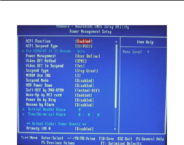
4.7 Power Management Setup
The power management setup controls the CPU card’s “green” features
to save power. The following screen shows the manufacturer’s defaults:
Figure 4.10: Power management setup screen
4.7.1 ACPI function
The choices: Enabled, Disabled.
ARK-3384 User Manual 46
4.7.2 ACPI Suspend Type
This field is used to select the type of Suspend mode. The setup options
are:
S1(POS): Enables the Power On Suspend function.
S3(STR): Enables the Suspend to RAM function.
4.7.3 Run VGABIOS if S3 Resume
When this field is set to Auto, the system will initialize the VGA BIOS
when it wakes up from the S3 state. This can be configured only if the
“ACPI Suspend Type” field is set to “S3(STR)” or “S1&S3” The setup
options are “Auto”, “Yes”, and “No”. The default setup value is “Auto”.
4.7.4 Power Management
This category allows you to select the type (or degree) of power saving
and is directly related to the following modes:
1. HDD Power Down
2. Suspend Mode
There are four selections for Power Management, three of which have
fixed mode settings
4.7.5 Video Off In Suspend
When the system is in suspend, the video will turn off.
4.7.6 Suspend Type
The options are “Stop Grant” and “PwrOn Suspend”.
Min. Power Saving Minimum power management., Suspend Mode = 1
hr., and HDD Power Down = 15 min.
Max. Power
Saving
Maximum power management., Suspend Mode = 1
min., and HDD Power Down = 1 min.
User Defined
(Default)
Allows you to set each mode individually. When not
disabled, each of the ranges are from 1 min. to 1 hr.
except for HDD Power Down which ranges from 1
min. to 15 min. and disable.
47 Chapter 4
4.7.7 Modem Use IRQ
This determines the IRQ in which the MODEM can use. The setup
options are: “3”, “4”, “5”, “7”, “9”, “10”, “11”, “NA”. The default setup
value is “3”
4.7.8 Suspend Mode
When the system enters suspend mode, the CPU and onboard peripherals
will be shut off. When enabled, and after the set time of system inactivity,
all devices except the CPU will be shut off.
4.7.9 HDD Power Down
You can choose to turn the HDD off after one of the time intervals listed,
or when the system is in “suspend” mode. If the HDD is in a power sav-
ing mode, any access to it will wake it up.
4.7.10 Soft-Off by PWR-BTTN
If you choose “Instant-Off”, then pushing the ATX soft power switch but-
ton once will switch the system to “system off” power mode. You can
choose “Delay 4 sec.” If you do, then pushing the button for more than 4
seconds will turn off the system, whereas pushing the button momentarily
(for less than 4 seconds) will switch the system to “suspend” mode.
4.7.11 Wake-Up by PCI card
Enabled: This field should be set to Enabled only if your PCI card such
as LAN card or modem card uses the PCI PME (Power Manage-
ment Event) signal to remotely wake up the system. Access to the
LAN card or PCI card will cause the system to wake up. Refer to
the card’s documentation for more information.
Disabled: The system will not wake up despite access to the PCI card
4.7.12 Power On By Ring
Set this field to Enabled to use the modem ring-on function. This will
allow your system to power-on to respond to calls coming from an exter-
nal modem.
4.7.13 PowerOn By Alarm
When Enabled, your can set the date and time at which the RTC (real
time clock) alarm awakens the system from Suspend mode. The choices:
Enabled, Disabled.
Enabled: When Enabled, you can set the date and time you would like
the Soft Power Down (Soft-Off) PC to power-on in the “Date (of
Month) Alarm” and “Time
ARK-3384 User Manual 48
(hh:mm:ss) Alarm” fields. However, if the system is being accessed by
incoming calls or the network (Resume On Ring/LAN) prior to
the date and time set in these fields, the system will give priority
to the incoming calls or network.
Disabled: Disables the automatic power-on function. (default)
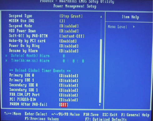
Figure 4.11: Power Management Setup
4.7.14 Date (of Month) Alarm
0 The system will power-on everyday according to the time set in the
“Time (hh:mm:ss) Alarm” field.
1-31 Select a date you would like the system to power-on. The system
will power-on on the set date, and time set in the “Time
(hh:mm:ss) Alarm” field.
4.7.15 Time (hh:mm:ss) Alarm
This is used to set the time you would like the system to power-on. If you
want the system to power-on everyday as set in the “Date (of Month)
Alarm” field, the time set in this field must be later than the time of the
RTC set in the Standard CMOS Features submenu.
4.7.16 Primary IDE 0/ 1 and Secondary IDE 0 / 1
When Enabled, the system will resume from suspend mode if Primary
IDE 0 / 1 or Secondary IDE 0 / 1 is active. The choice: Enabled, Disabled.

49 Chapter 4
4.7.17 FDD, COM, LPT PORT
When Enabled, the system will resume from suspend mode if FDD, COM
port, or LPT port is active. The choice: Enabled, Disabled.
4.7.18 PCI PIRQ [A-D]#
When Enabled, the system will resume from suspend mode if interrupt
occurs. The choice: Enabled, Disabled.
4.7.19 PWRON After PWR-Fail
Off When power returns after an AC power failure, the system’s power
is off. You must press the Power button to power-on the system.
On When power returns after an AC power failure, the system will
automatically power-on
Former-StsWhen power returns after an AC power failure, the system
will return to the state where you left off before power failure
occurs. If the system’s power is off when AC power failure
occurs, it will remain off when power returns. If the system’s
power is on when AC power failure occurs, the system will
power on when power returns.
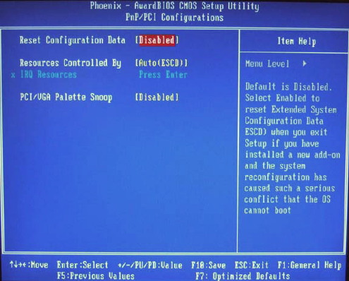
4.8 PnP/PCI Configurations
This section shows how to configure the PCI bus system. It covers some
very technical items and it is strongly recommended that only experi-
enced users should make any changes to the default settings.
4.8.1 Reset Configuration Data
Default is Disable. Select Enable to reset Extended System Configuration
Data (ESCD) if you have installed a new add-on and system configura-
tion has caused such a conflict that OS cannot boot.
Enabled: The BIOS will reset the Extended System Configuration Data
(ESCD) once automatically. It will then recreate a new set of
configuration data.
Disabled: The BIOS will not reset the configuration data.
ARK-3384 User Manual 50
Figure 4.12: PnP/PCI configurations screen
4.8.2 Resources controlled by
The Award Plug and Play BIOS has the capability to automatically con-
figure all of the boot and Plug and Play compatible devices.
Auto (ESCD): The system will automatically detect the settings for you.
Manual: Choose the specific IRQ resources in the “IRQ Resources” field.
4.8.3 IRQ Resources
Move the cursor to this field and press <Enter>. The “IRQ-3” to “IRQ-
15” fields will appear. Set each system interrupt to either PCI Device or
Reserved.
4.8.4 PCI/VGA Palette Snoop
This field determines whether the MPEG ISA/VESA VGA cards can
work with PCI/VGA or not. The default value is Disabled.
EnabledMPEG ISA/VESA VGA cards work with PCI/VGA.
DisabledMPEG ISA/VESA VGA cards does not work with PCI/VGA.
51 Chapter 4
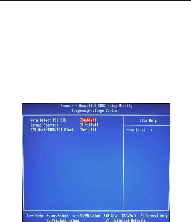
4.9 Frequency/Voltage Control
This section shows the user how to configure the processor frequency.
4.9.1 Auto Detect PCI CLK
This field enables or disables the auto detection of the PCI clock.
4.9.2 Spread Spectrum
This field sets the value of the spread spectrum. The default setting is Dis-
abled. Leave this field in its default setting. Do not alter this setting unless
advised by an engineer or technician.
4.9.3 CPU Host/3V66/PCI Clock
Leave this field in its default setting. Do not alter this setting unless
advised by an engineer or technician.
Figure 4.13: Frequency/Voltage Control

ARK-3384 User Manual 52
4.10 Load Optimized Defaults
This option allows you to load the default values to your system configu-
ration. These default settings are optimal and enable all high performance
features.
4.11 Set Password
To change the password:
1. Choose the “Set Password” option from the “Initial Setup Screen”
menu and press <Enter>.
The screen will display the following message:
Please Enter Your Password
Press <Enter>.
2. If the CMOS is good or if this option has been used to change the
default password, the user is asked for the password stored in the CMOS.
The screen will display the following message:
Please Confirm Your Password
Enter the current password and press <Enter>.
3. After pressing <Enter> (ROM password) or the current password
(user-defined), you can change the password stored in the CMOS. The
password must be no longer than eight (8) characters.
Remember, to enable the password setting feature, you must first select
either “Setup” or “System” from the “Advanced BIOS Features” menu.
4.12 Save & Exit Setup
If you select this and press <Enter>, the values entered in the setup utili-
ties will be recorded in the CMOS memory of the chipset. The micropro-
cessor will check this every time you turn your system on and compare
this to what it finds as it checks the system. This record is required for the
system to operate.
4.13 Exit Without Saving
Selecting this option and pressing <Enter> lets you exit the setup program
without recording any new values or changing old ones.

5
CHAPTER
PCI SVGA/LCD Setup
This chapter details the software con-
figuration information. It shows you
how to configure the card to match
your application requirements. The
AWARD System BIOS is covered in
Chapter 4.
Sections include:
• Introduction
• Installation of SVGA drivers for
Windows 2000/XP
ARK-3384 User Manual 54
Chapter 5 PCI SVGA/LCD Setup
5.1 Introduction
The board has an onboard Intel 852GM/855GME chipset for its AGP/
SVGA controller. It supports LVDS LCD displays and conventional ana-
log CRT monitors with 64MB frame buffer shared with system memory.
The VGA controller can drive CRT displays with resolutions up to 1600
x 1200@85-Hz and 2048 x 1536 @75Hz and support 2 channel LVDS
display mode up to UXGA panel resolution with frequency range from
25-MHz to 112-MHz
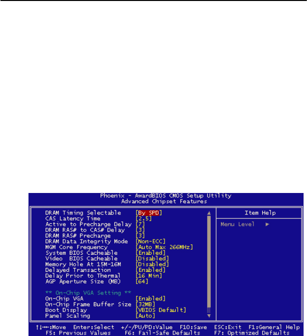
5.1.1 CMOS setting for Boot Display type
The ARK-3384 system BIOS and custom drivers are located in a 4 Mbit,
Flash ROM device, designated U7 of system motherboard of ARK-3384.
A single Flash chip holds the system BIOS, VGA BIOS and network
Boot ROM image. The display can be configured via CMOS settings, by
choice the selection items of “Boot display” of Advanced Chipset Fea-
tures sections of Award BIOS Setup.
Figure 5.1: Advanced Chipset features screen
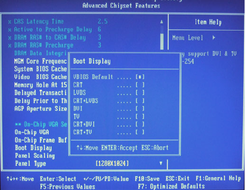
55 Chapter 5
Figure 5.2: Boot Display Selection
The ARK-3384 can be set in one of four configurations: on a CRT, on a
LVDS based of flat panel display, or on both CRT+LVDS for simulta-
neous or dual independent displays. The system is initially set to
“VBIOS-Default” to allow system to detect the connected display device
automatically.
5.1.2 Dual Independent Display
The ARK-3384 uses an Intel 855GME or Intel 852GM controller that is
capable of providing multiple views and simultaneous display with mixed
video and graphics on a flat panel and CRT. To set up dual display
under2000/XP, please follow these steps:
1. Select “Start”, “Control panel”, “Display”, "Setting", "Advanced",
"Graphics Properties", "Device".
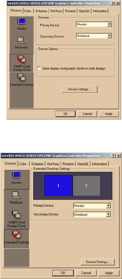
ARK-3384 User Manual 56
Figure 5.3: Intel® 82852/82855 GM/GME Graphics Controller Properties –
Devices
2. Select “1” for current display, or “2” for second display.
Figure 5.4: Intel® 82852/82855 GM/GME Graphics Controller Properties –
Extended Desktop Settings
57 Chapter 5
3. Enable “Extend my Windows desktop onto this monitor”.
4. Click “OK”.
5.2 Installation of the SVGA Driver
Complete the following steps to install the SVGA driver. Follow the pro-
cedures in the flow chart that apply to the operating system that you are
using within your ARK-3384.
5.2.1 Installation for Windows 2000/XP
To install SVGA driver for Window 2000/XP, please run the setup wiz-
ard “Intel Extreme Graphic 2” in CD-ROM. Example of installation is
shown as bellow:
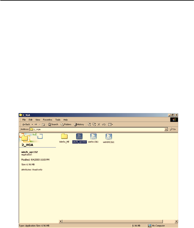
1. You can find Win2000/XP VGA driver from the path at the direc-
tory of ARK-3384 CD-ROM:
D:\ARK-33384 Series Software Device
Driver\2_VGA\win2k_xp141.exe,
then double click “win2k_xp141” to run “Install Shield Wizard”
Figure 5.5: CD Directory “2.VGA”
• Notes: The windows illustrations in this chapter are intended as
examples only. Please follow the listed steps, and pay attention to
the instructions which appear on your screen.
• For convenience, the CD-ROM drive is designated as "D" through-
out this chapter.
ARK-3384 User Manual 58
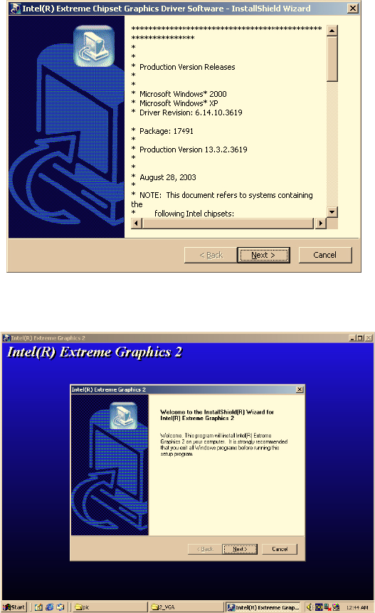
2. Double click "setup" and "next" into setup wizard.
Figure 5.6: Intel® Extreme Chipset Graphics Driver Software Install Wiz-
ard
Figure 5.7: Intel® Extreme Graphics Driver Setup
3. Restart computer when installation finished.
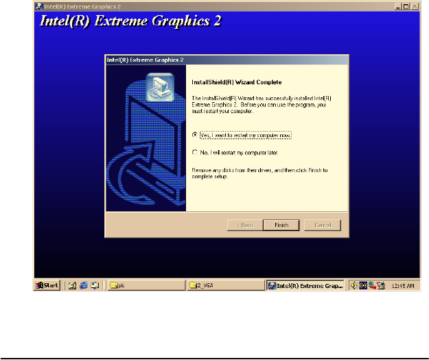
59 Chapter 5
Figure 5.8: InstallShield® Wizard Complete
5.3 Further information
For further information about the AGP/VGA installation in your ARK-
3384, including driver updates, troubleshooting guides and FAQ lists,
visit the following web resources:
Intel website: www.intel.com
Advantech websites: www.advantech.com, or www.advantech.com.tw
ARK-3384 User Manual 60

6
CHAPTER
Audio Setup
The ARK-3384 is equipped with an
audio interface that records and plays
back CD-quality audio. This chapter
provides instructions for installing the
software drivers included on the audio
driver diskettes.
ARK-3384 User Manual 62
Chapter 6 Audio Setup
6.1 Introduction
The ARK-3384’s audio interface provides high-quality stereo sound and
FM music synthesis (ESFM) by using the Intel ICH4 audio controller.
The audio interface can record, compress, and play back voice, sound,
and music with built-in mixer control.
6.2 Driver installation
6.2.1 Before you begin
Please read the instructions in this chapter carefully before you attempt
installation. The audio drivers for the ARK-3384 board are located on the
audio driver CD. Run the supplied SETUP program to install the drivers;
don’t copy the files manually.
Note: The files on the software installation diskette are com-
pressed. Do not attempt to install the drivers by copying the files manu-
ally. You must use the supplied SETUP program to install the drivers.
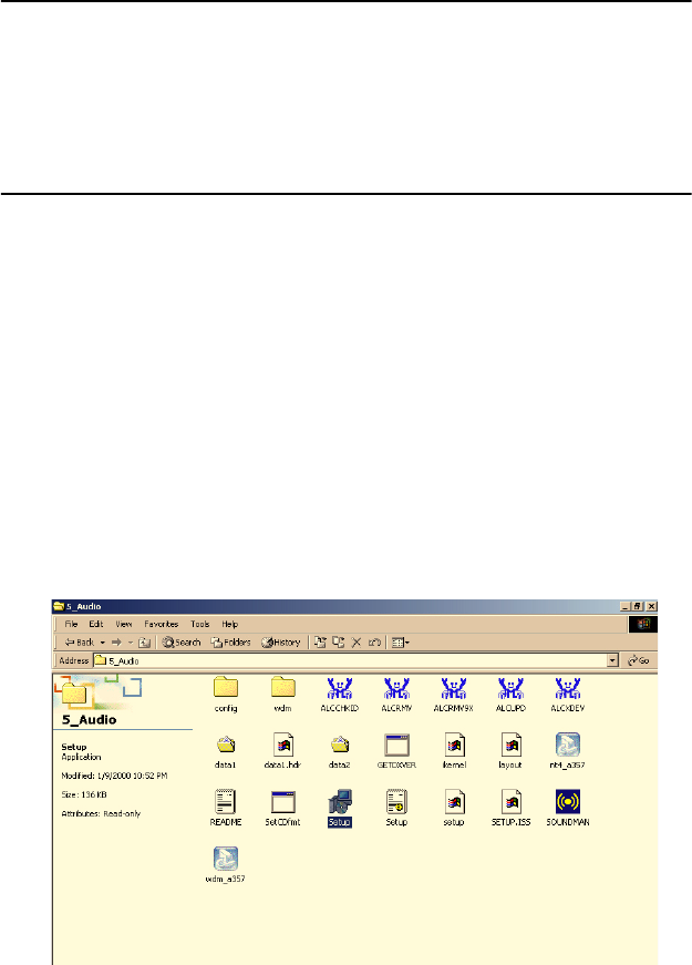
6.2.2 Windows 2000/XP drivers
1. Find Win 2000/XP Audio driver folder at the directory “5_Audio”
from the Driver & Utility CD-ROM disk, click “setup” to start the instal-
lation process.
Figure 6.1: Directory of Audio Driver
63 Chapter 6
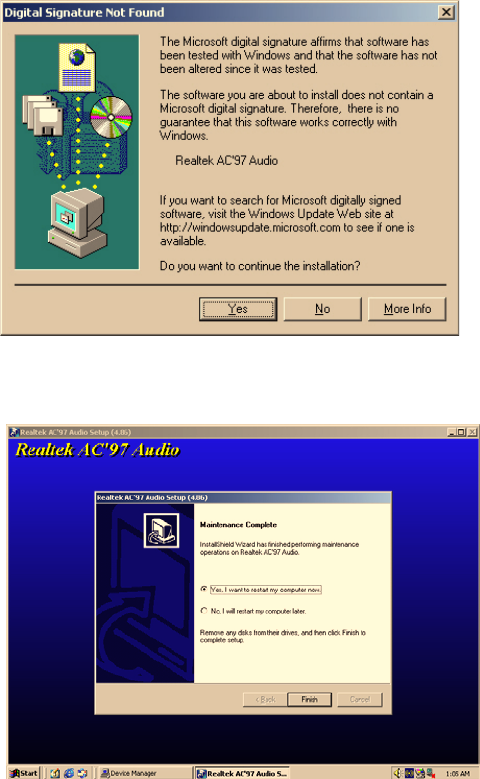
Figure 6.2: AC97 Audio Driver Installation
2. Click "yes" to reboot your computer.
Figure 6.3: Installation Complete of AC97 Audio Driver
ARK-3384 User Manual 64

7
CHAPTER
Ethernet Setup
This chapter provides information on
Ethernet configuration.
Sections include:
• Introduction
• Installation of Ethernet drivers
for Windows
• 2000/XP
• Further information

ARK-3384 User Manual 66
Chapter 7 Ethernet Setup
7.1 Introduction
The ARK-3384 is equipped with a high performance 32-bit Ethernet
chipset which is fully compliant with IEEE 802.3 100 Mbps CSMA/CD
standards. They are supported by major network operating systems. They
are also both 100Base-T and 10Base-T compatible. The network boot
feature can be utilized by incorporating the boot ROM image files for the
appropriate network operating system. The boot ROM BIOS files are
combined with system BIOS, which can be enabled/disabled in the BIOS
setup.
7.2 Installation of Ethernet driver
Before installing the Ethernet driver, note the procedures below. You
must know which operating system you are using in your ARK-3384
Series, and then refer to the corresponding installation flow chart. Then
just follow the steps described in the flow chart. You will quickly and
successfully complete the installation, even if you are not familiar with
instructions for MS-DOS or Windows.
7.2.1 Installation for Windows 2000/XP
1. Select "Start", "Settings". "Control Panel".
Note: The windows illustrations in this chapter are examples only.
Follow the steps and pay attention to the instructions which appear on
your screen.
2. Double click "Add/Remove Hardware".
67 Chapter 7
Figure 7.1: Windows Control Panel Screen
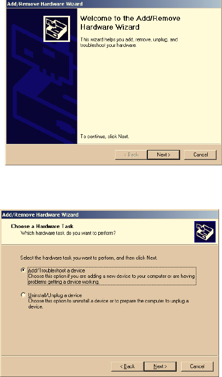
3. Click “Next” and prepare to install network function
Figure 7.2: Add/Remove Hardware Wizard
4. Choose “Add/Troubleshoot a device” and click “Next”.
Figure 7.3: Choose a Hardware Task Screen
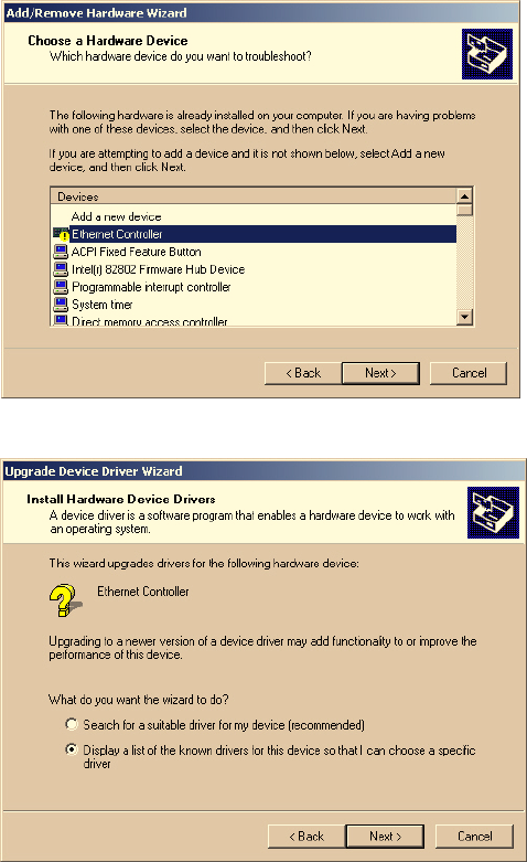
5. Choose Hardware Device “Ethernet Controller”
ARK-3384 User Manual 68
Figure 7.4: Choose a Hardware Device
Figure 7.5: Install Ethernet Controller Screen
69 Chapter 7
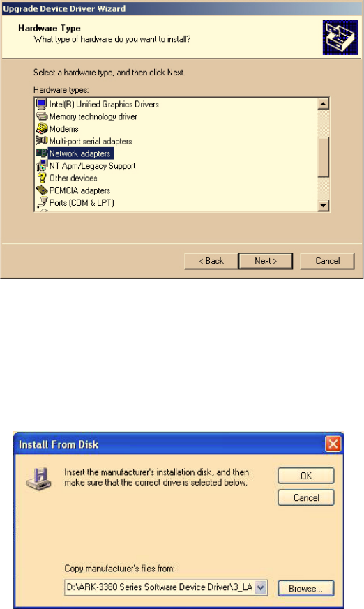
Figure 7.6: Hardware Type Screen
6. Insert the ARK-3384’s Driver & Utility CD-ROM Disk into D: drive
6-1. Find the driver of chipset folder “82551QM” at the directory of
“D:\ARK-3384 Series Software Device Driver\3_LAN” from ARK-
3384’s Driver & Utility CD-ROM Disk, click “setup” to start the installa-
tion process.
6-2. Click “OK”.
Figure 7.7: Install From Disk Screen
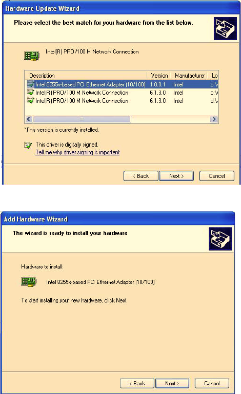
7. Choose the “Intel 8255x-based PCI Ethernet Adapter (10/100)” item
Click “Next”
ARK-3384 User Manual 70
Figure 7.8: Network Adapter Selection Screen
Figure 7.9: Start Device Driver Installation
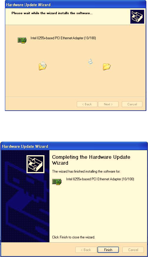
8. Please wait while the wizard installs the software.
71 Chapter 7
Figure 7.10: Intel Ethernet Adapter driver installation screen
9. Click “OK”
Figure 7.11: Intel Ethernet Adapter Driver Installation Complete Screen
ARK-3384 User Manual 72

8
CHAPTER
IEEE 802.11b/g
Wireless LAN Setup
This chapter provides information on
software driver installation of IEEE
820.11b/g Wireless LAN
Sections include:
• Introduction
• Installation of Ethernet drivers
for Windows
• 2000/XP
• Further information
ARK-3384 User Manual 74
Chapter 8 IEEE 802.11b/g Wireless
LAN Setup
8.1 Introduction
The ARK-3384 is equipped with Wireless LAN interface that is fully
compliant with IEEE 802.11b and 802.11g standard protocol and oper-
ates in the 2.4GHz frequency bands with support of data speed up to
54Mbps. It empowers your notebook to access wireless network instantly
with maximum 54Mbps throughput. The Wireless LAN interface of
ARK-3384 is equipped with the most secure enhancement to save your
important information from hacking. It also supports popular operating
systems with great compatibility.
8.2 Installation of IEEE 820.11b/g Wireless LAN’s
driver
8.2.1 Installation for Windows XP
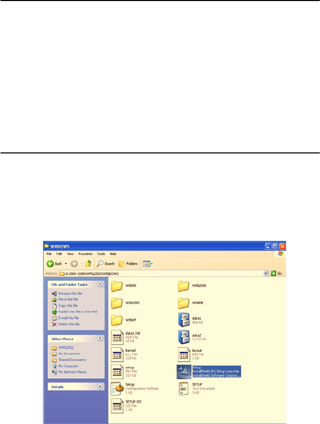
1. Find Windows XP Wireless LAN driver folder at the directory of
“Disk Drive Letter:\......\ARK-3380 Series Software Device
Driver\7_WLAN” from the Driver & Utility CD-ROM disk, click “setup”
to start the installation process.
Figure 8.1: Directory folder of Wireless LAN
75 Chapter 8
Figure 8.2: Directory folder of Wireless LAN
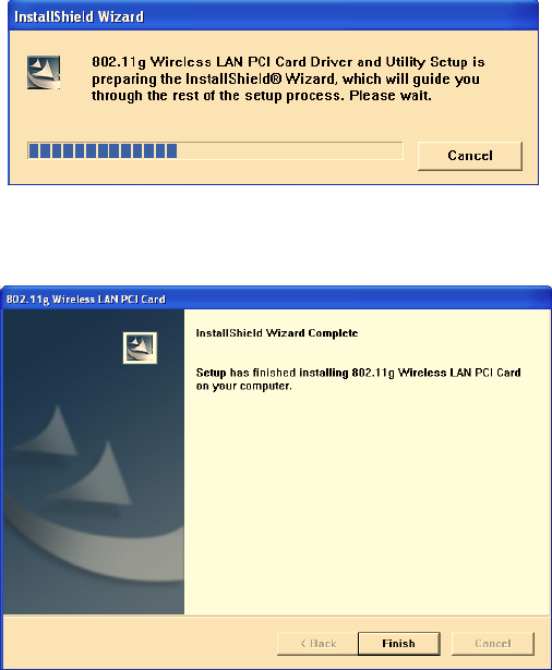
2. Click “Finish” to complete the driver installshield wizard.
Figure 8.3: Installshield Wizard Complete
3. A Easy Configuration Utility will shows on screen automatically,
after complete the driver installshield wizard.
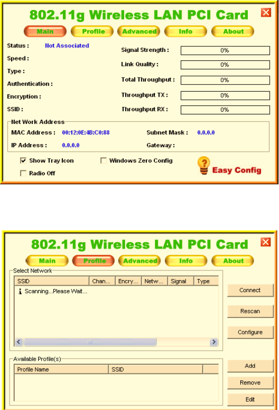
ARK-3384 User Manual 76
Figure 8.4: “Easy Config” Utility for Wireless LAN
4. Please choose the “Profile” button to scan wireless network
Figure 8.5: “Profile” configuration screen
5. The Configuration utility display the available wireless network list
for your selection, please refer to Figure 8.6. User can configure the secu-
rity data profile that required to connect with the selected wireless net-
work by clicking “configure”.
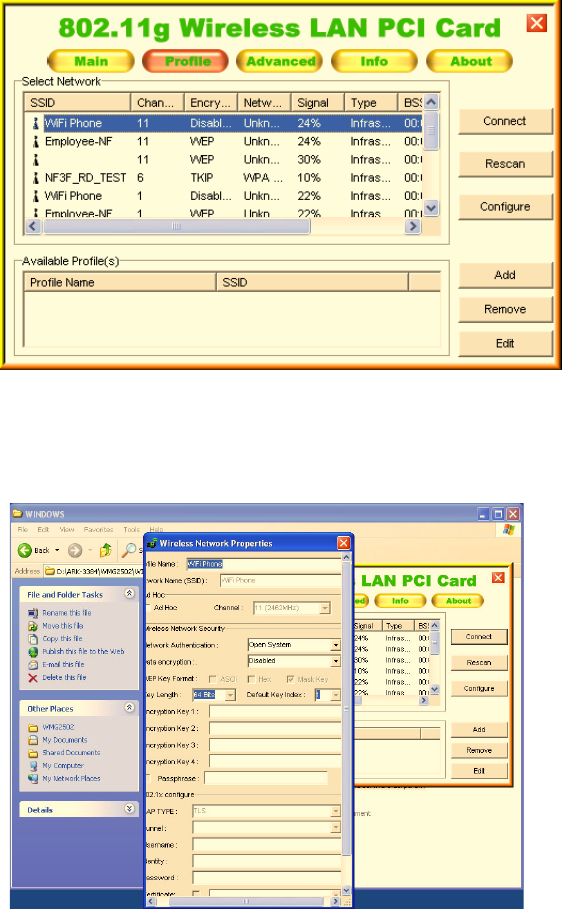
77 Chapter 8
Figure 8.6: “Profile” configuration screen
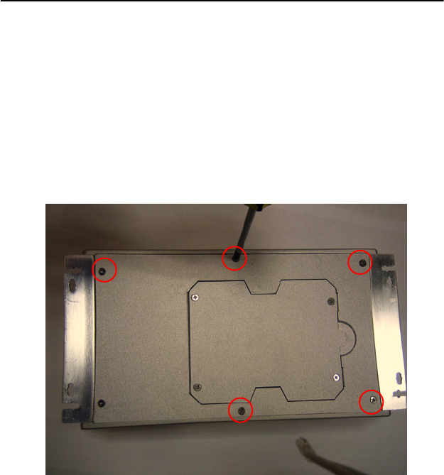
6. The Wireless Network Properties will shows on screen after click-
ing the “configure” to allow user configuration for the security data pro-
file that required to connect with the selected wireless network.
Figure 8.7: “Profile” configuration screen
7. Click “Connect” to connect to the selected wireless network.
ARK-3384 User Manual 78

9
CHAPTER
Full Disassembly Pro-
cedure
This chapter details the system disas-
sembling procedure for setting up the
jumpers and for maintenance.
Sections include:
ARK-3384 User Manual 80
Chapter 9 Full Disassembly Procedure
9.1 Introduction
If you want to completely disassemble the ARK-3384 embedded box
computer, follow the step-by-step procedures below. Users should be
aware that Advantech Co., Ltd. takes no responsibility whatsoever for
any problems or damage caused by the disassembly of the ARK-3384
embedded box computer. Make sure the power cord of the ARK-3384
embedded box computer is unplugged before you start. The following
procedures do not include the detailed disassembly procedures for the
HDD, Compact Flash Disk and SRAM; all of which can be found in
Chapter 3.
1. Unscrew the 6 screws on the bottom side
Figure 9.1:
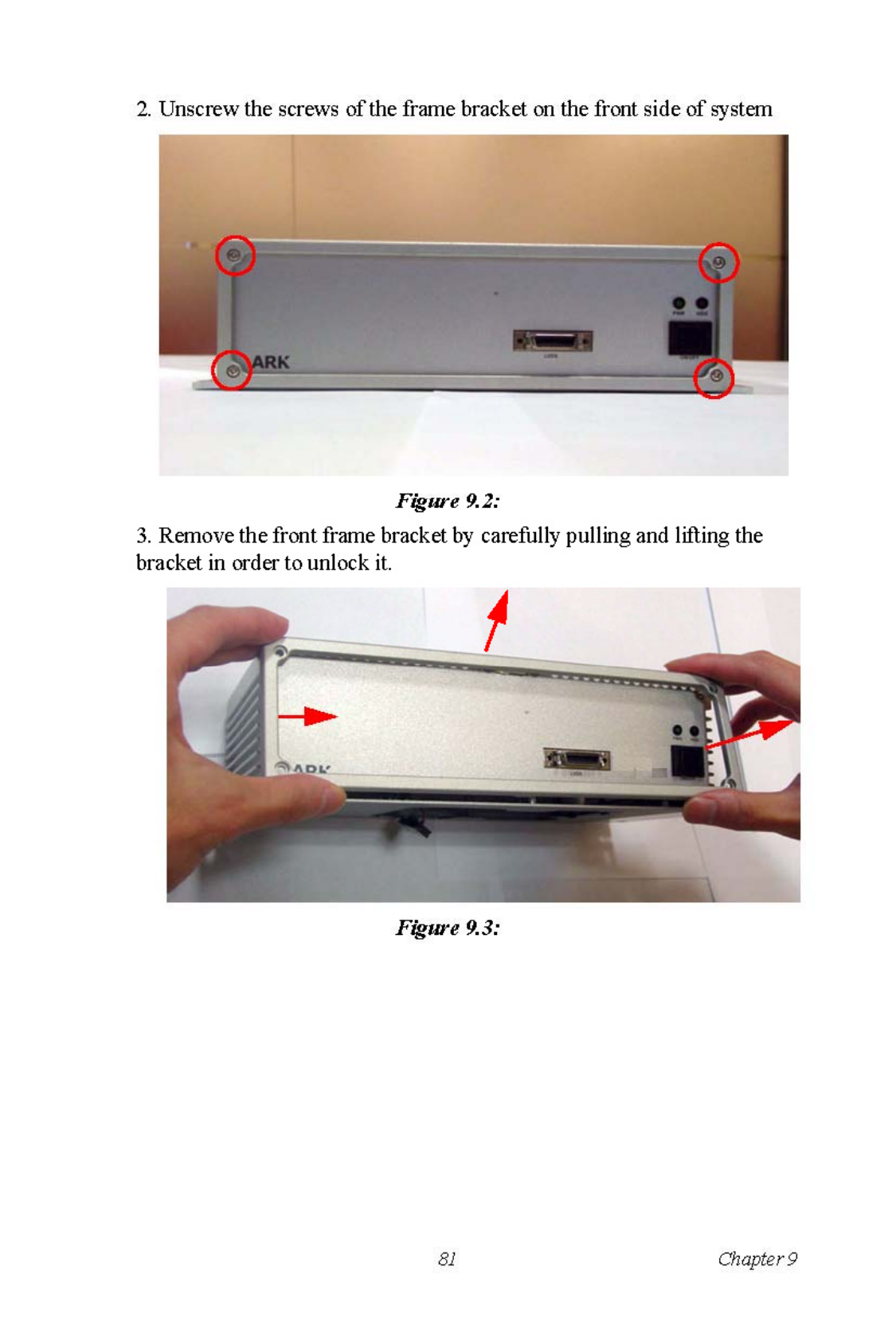
ARK-3384 User Manual 84
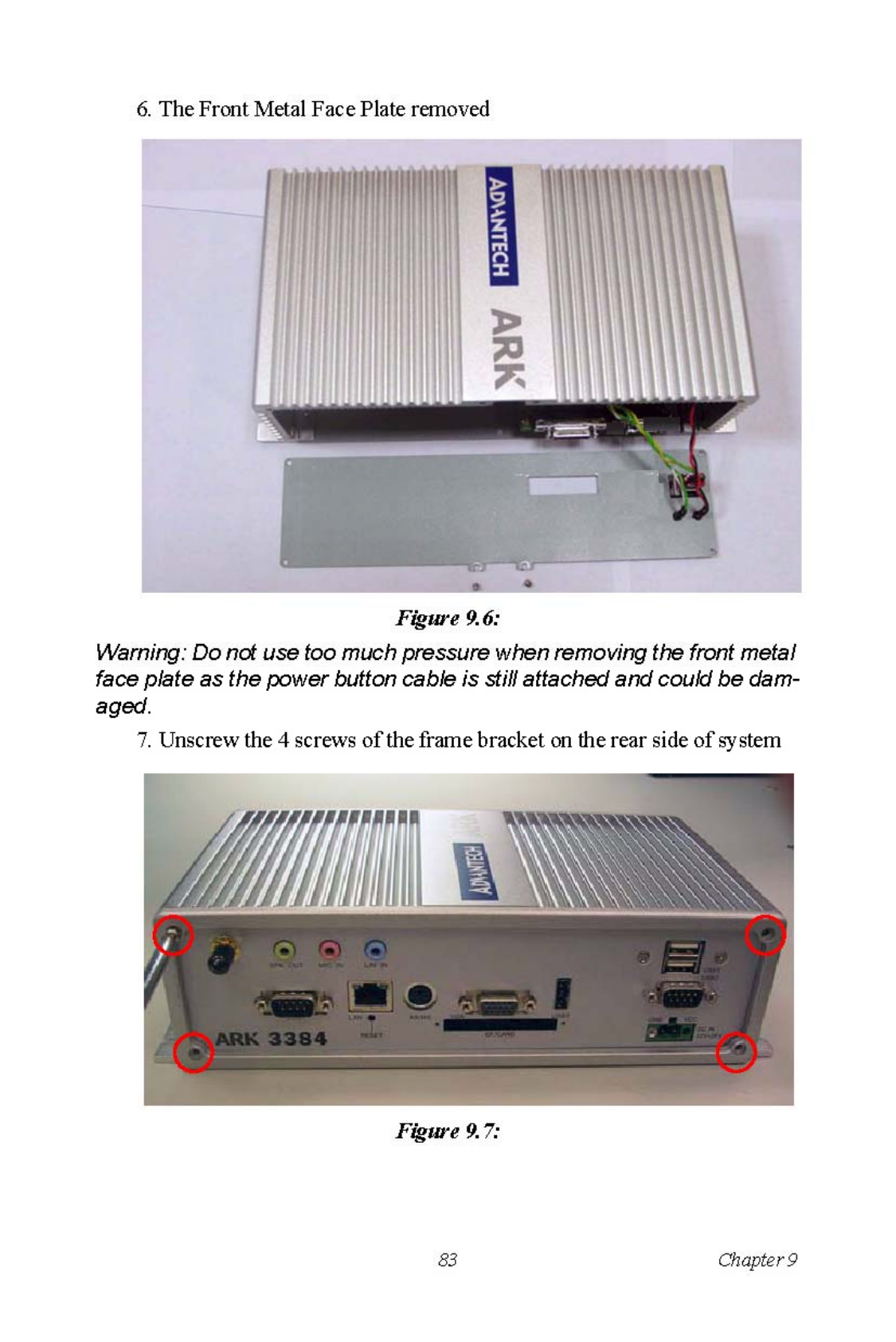
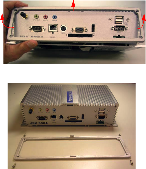
8. Remove the rear frame bracket by carefully pulling and lifting the
bracket in order to unlock it
Figure 9.8:
9. The rear frame bracket removed.
Figure 9.9:
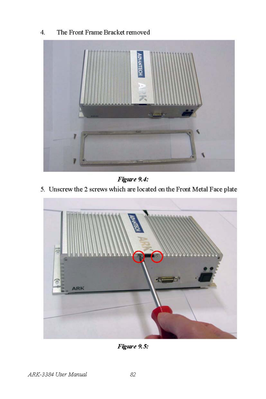
10. Unscrew the 2 screws which are located on the Rear Metal Face plate
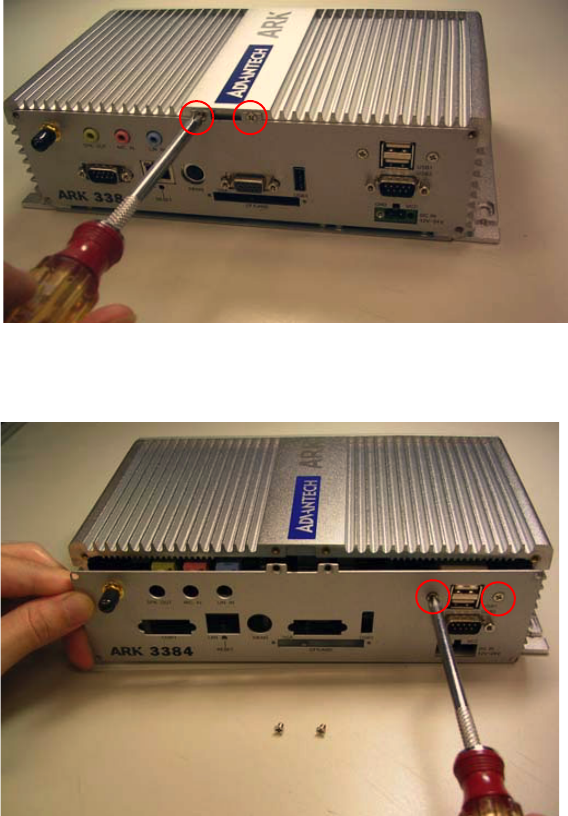
85 Chapter 9
Figure 9.10:
11. Unscrew the 2 screws which fixed the “USB2&USB3 port” on the
Rear Metal Face Plate
Figure 9.11:
12. Unscrew the 2 screws which fixed the “COM2 port” on the Rear
Metal Face Plate
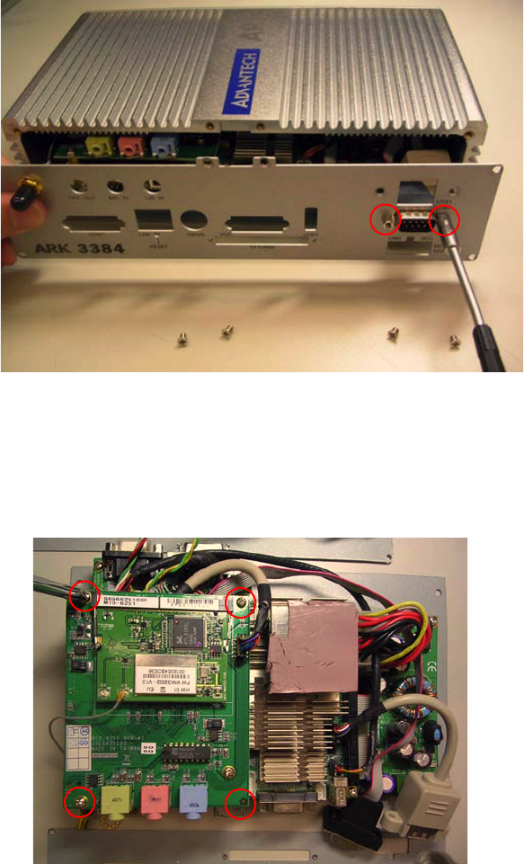
ARK-3384 User Manual 86
Figure 9.12:
Warning: Do not use too much pressure when removing the front metal
face plate as the COM2 connector cable is still attached and could be
damaged.
14. Unscrews the 4 screws which fixed the MIO-6251 Module I/O board
to the system board.
Figure 9.13:
87 Chapter 9
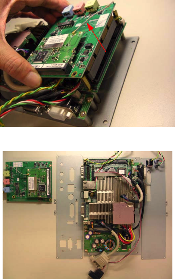
15. Remove MIO-6251 Module I/O board from MIO Socket of system
board
Figure 9.14:
16. The MIO-6251 Module I/O board removed from system.
Figure 9.15:
ARK-3384 User Manual 88
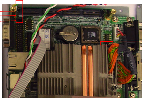
17. Jumper Location on PCM-9380/PCM-9386 Motherboard
Figure 9.16:
J6 LCD
Power
Setting
J3
J5
J4
COM 2
Settings
REMARK:
IEEE 802.11b or 802.11g operation of this product in the U.S.A. is firmware-limited to channels 1
through 11.
You are cautioned that changes or modifications not expressly approved by the party responsible
for compliance could void your authority to operate the equipment.
1.•This transmitter must not be co-located or operating in conjunction with any other antenna or
transmitter.
2.•This equipment complies with FCC RF radiation exposure limits ser forth for an uncontrolled
environment. This equipment should be installed and operated with a minimum distance of 20
centimeters between the radiator and your body.