Advantech Co ARK2250L Computer User Manual V4 12 EC User Manual
Advantech Co Ltd Computer V4 12 EC User Manual
UserManual.wiki
>
Advantech Co
>
ARK2250L User Manual
User Manual
Navigation menu
Upload a User Manual
Namespaces
Wiki Guide
HTML
PDF
Info
Views
User Manual
Discussion / Help
Navigation


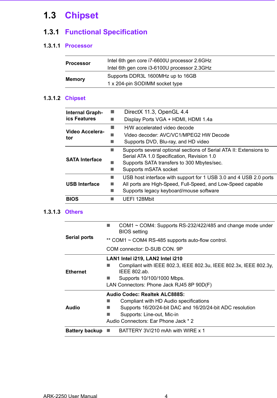
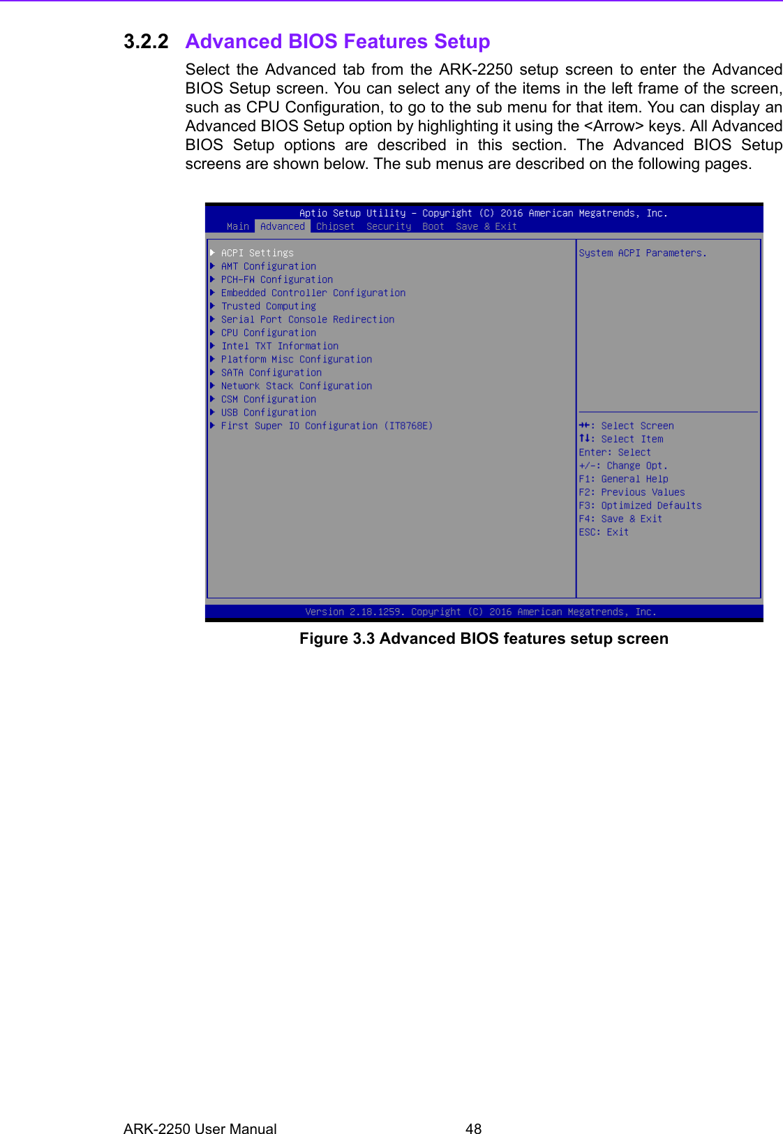
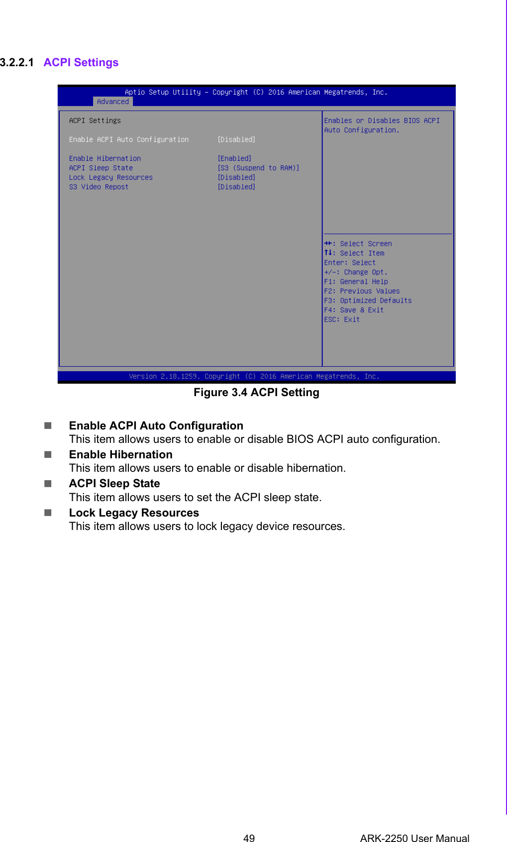
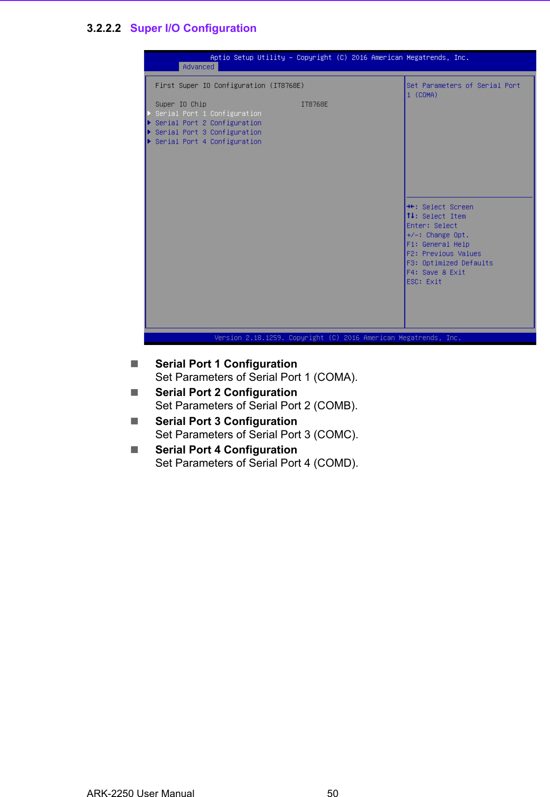
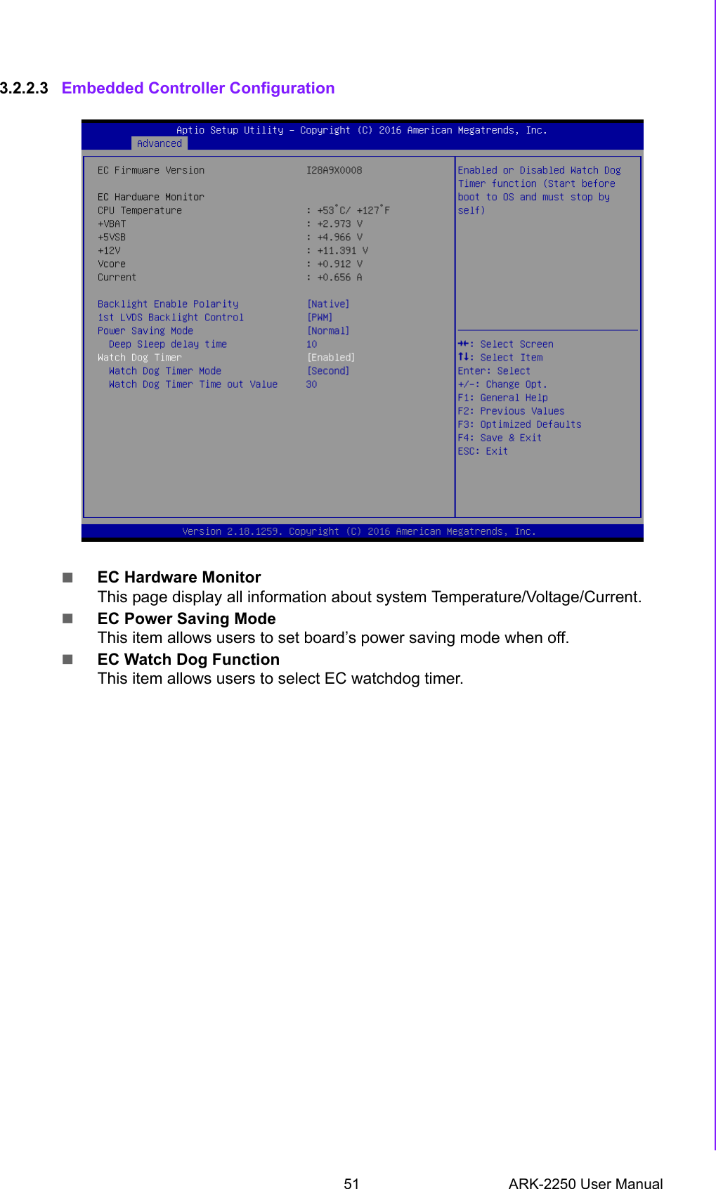
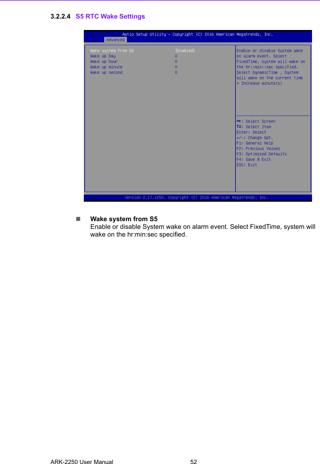
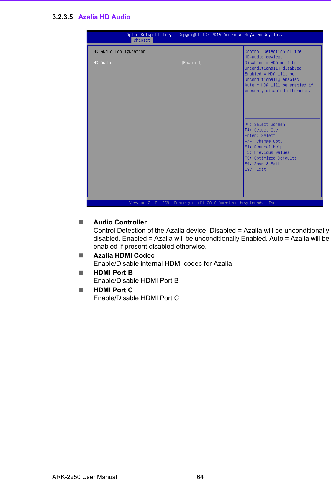
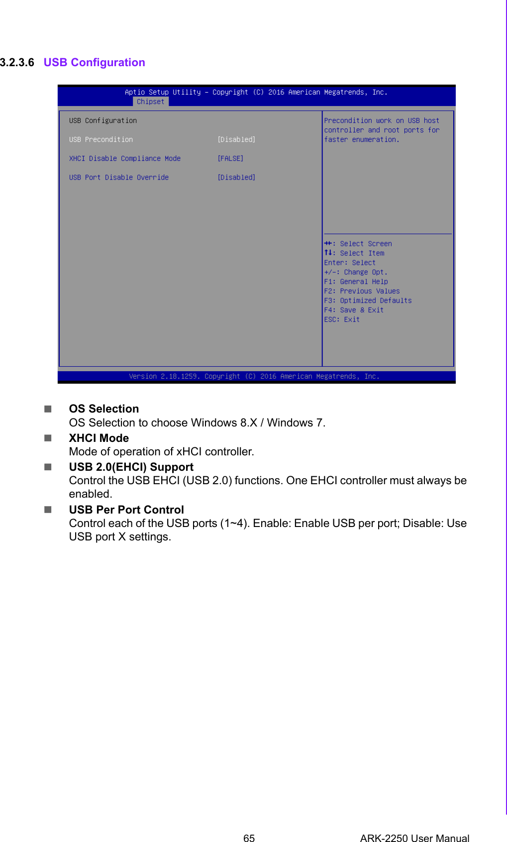
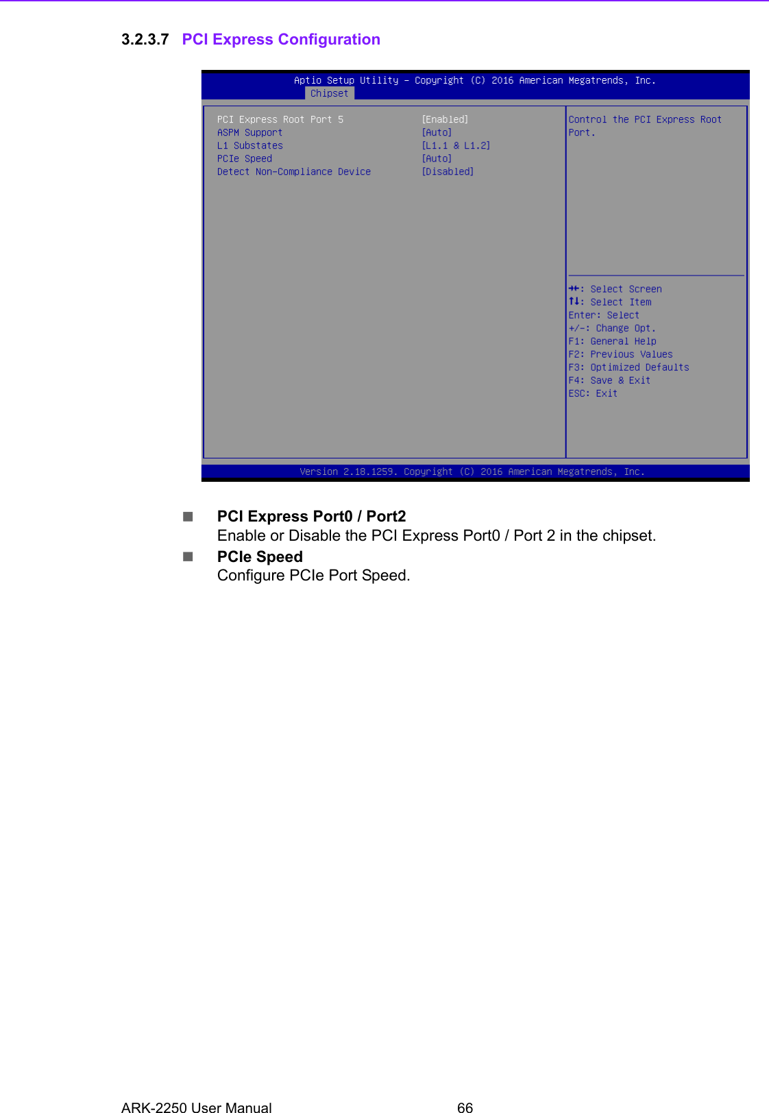
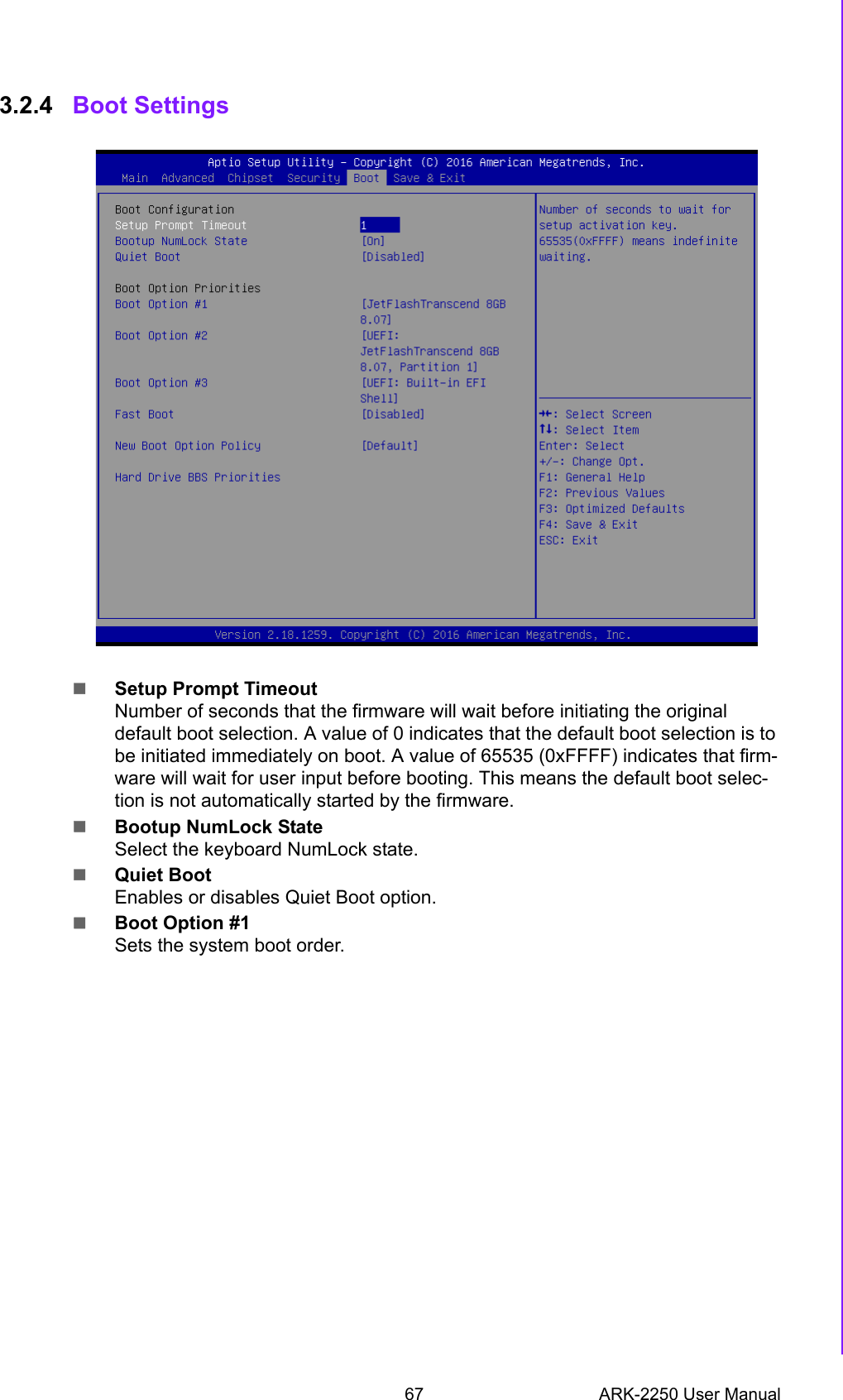
![5 ARK-2250 User ManualChapter 1 General Introduction1.3.2 WISE-PaSS/RMM1.4 Mechanical Specifications1.4.1 Dimensions260[10.24] x 54[2.13] x 140.2[5.52] Unit: mm [Inch]Figure 1.1 ARK-2250 Mechanical dimension drawing1.4.2 Weight2.3 kg (5.06 lb)1.5 Power Requirement1.5.1 System PowerMinimum power input: –ARK-2250: DC 12V, 5A1.5.2 RTC BatteryLithium 3 V/210 mAHSequence control SupportedWatchdog timer Multi Level WDT Programmable 1-255 sec / minHardware monitor CPU Temperature / input Current / input VoltagePower saving Deep sleep S5 mode System information Running HR / Boot record](https://usermanual.wiki/Advantech-Co/ARK2250L/User-Guide-3959324-Page-15.png)