Advantech Co DLV4108 Computer User Manual Quickstart Guide
Advantech Co Ltd Computer Quickstart Guide
Contents
- 1. User Manual
- 2. User Manual Safety Guide
User Manual
Quick Start Guide
DLT-V4108 Industrial PC
DLoG GmbH, 2016
Quick Start Guide DLT-V4108, V001 PN:2005410820
1 / 15
1
Introduction – for your safety
Read and observe the quick start
guide carefully.
Keep for future reference.
Read and observe the accompanying
“DLT-V4108 Safety Instructions”
carefully.
Go to www.advantech-dlog.com for
detailed manuals, e.g. “DLT-V4108
Manual” and “MDevice Manual”.
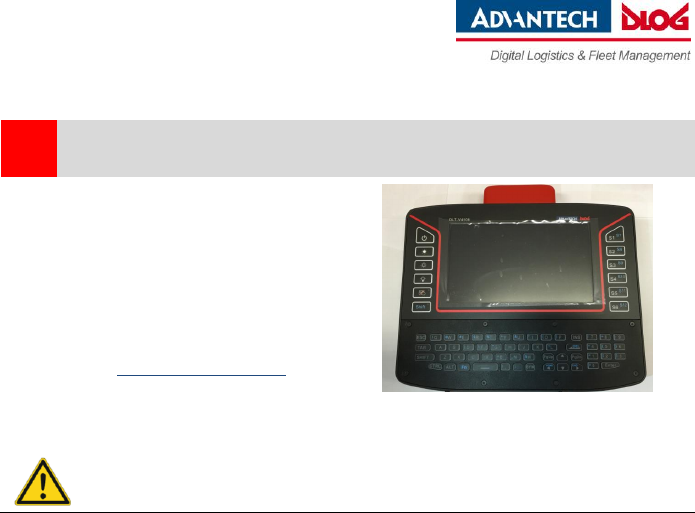
Figure: DLT-V4108 Industrial PC
DANGER
Observe the intended use.
Observe the intended use of DLT-V4108, e.g.: no use in EX zone (potentially explosive) and on ships, no
use in life-supporting systems or security-critical facilities.
Observe the required qualification.
This quick start guide is intended for qualified skilled personnel. Only skilled personnel may transport,
store, commission and maintain the DLT-V4108. Qualified and skilled personnel referred in this quick start
guide are persons who are familiar with these processes and have the corresponding qualifications for
their activities.
Hazardous voltage, electric shock from contact with live parts.
Do not put DLT-V4108 into operation if it is damaged.
Do not open or modify DLT-V4108.
Only connect or disconnect electrical connections when the device is in a de-energized state
(electrically dead)
Operators of the DLT-V4108 must be trained in the handling of the device.
DLT-V4108 is intended to be supplied by DC power source, rated _9-60 Vdc, 5 A minimum and
Tma _45 degree C maximum, if need further assistance, please contact Advantech for further
information."
Users must be trained / instructed.
Users of the DLT-V4108 must be trained by skilled personnel and instructed about the operation of the
device.
Quick Start Guide
DLT-V4108 Industrial PC
2 / 15
Quick Start Guide DLT-V4108, V001
DLoG GmbH, 2016
CAUTION
Replaceable Battery.
RISK OF EXPLOSION IF BATTERY IS REPLACED BY AN INCORRECT TYPE.
DISPOSE OF USED BATTERIES ACCORDING TO THE INSTRUCTIONS.
Design method in our quick start guide:
Hazards that pose a risk to life and limb - Personal injury
Possible property damage:
DANGER / WARNING / CAUTION
DANGER: Danger that immediately leads to death or
severe injury.
WARNING: Danger that can lead to death or severe
injury.
CAUTION: Danger that can lead to slight injuries.
NOTICE:
Physical damage
Information about possible
physical damage.
2
Technical data of DLT-V4108
DLT-V4108
Weight
3.35 kg
Dimensions
290 x 230 x 60.5 mm (width x height x depth)
Operating temp.
-20 to +45 °C
Storage temp.
-20 to +50 °C
Relative humidity
10~95% non-condensing, ambient temperature 25 °C
IP Protection class
IP65
Quick Start Guide
DLT-V4108 Industrial PC
DLoG GmbH, 2016
Quick Start Guide DLT-V4108, V001 PN:2005410820
3 / 15
3
Operation of DLT-V4108
NOTICE: Physical damage
Users of DLT-V4108 must be trained by skilled personnel and instructed about the operation of the
device.
Enter data
You can enter data using the touchscreen and the built in integrated keyboard.
Operate the touchscreen with:
Clean, dry fingers.
Clean, dry, thin gloves.
Suitable touch stylus
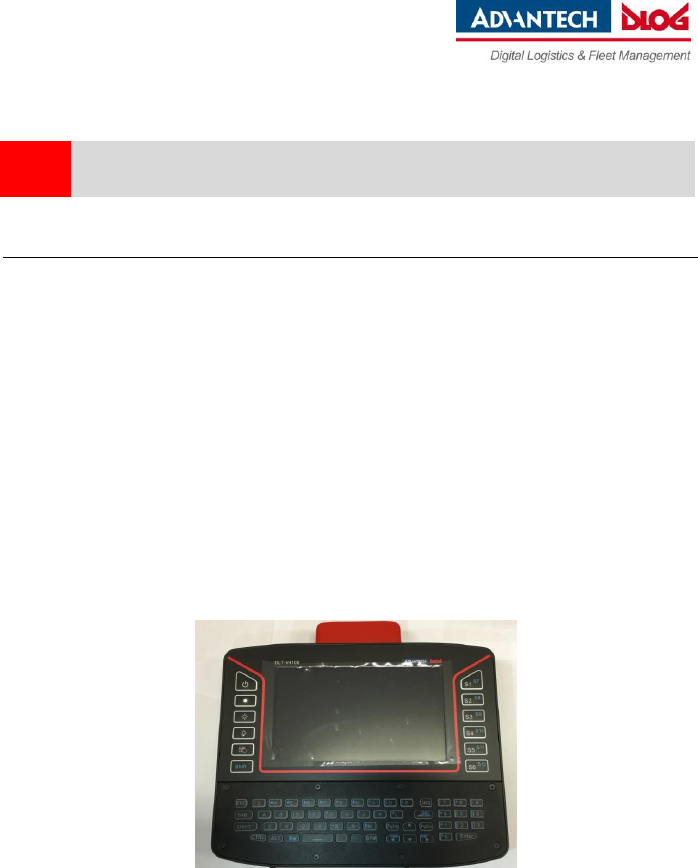
Front keys
Left side:
- Power on/off
- Display brighter
- Display darker
- Backlighting on/off
- Touchscreen on/off
- SHIFT
Right side:
- S1 to S12
programmable keys

Quick Start Guide
DLT-V4108 Industrial PC
4 / 15
Quick Start Guide DLT-V4108, V001
DLoG GmbH, 2016
LED indication on “Power ON /OFF “Key
System Status
LED Status
Color
System power on
Static
Green
System power off
Off
x
System over/under temperature
Static
Red
System UPS Battery is charging
Static
Orange
System thermal sensor faculty
Blinking
0.5 sec. on / 0.5 sec. off
Red
System UPS Battery Capacity Low
Blinking
0.2 sec. on / 0.8 sec. off
Orange
System is powered by UPS battery only
Blinking
0.5 sec. on / 0.5 sec. off
Green
LED indication on “Touch ON/OFF “Key
Touch Status
LED Status
Color
Touch function ON
Off
x
Touch function OFF
Static
Orange
LED indication on “SHIFT “Key
System Status
LED Status
Color
System switch to S1/S2/S3/S4/S5/S6
Off
x
System switch to S7/S8/S9/S10/S11/S12
Static
Orange
Quick Start Guide
DLT-V4108 Industrial PC
DLoG GmbH, 2016
Quick Start Guide DLT-V4108, V001 PN:2005410820
5 / 15
4
Software configuration with MDevice
DLT-V4108 Industrial PCs are configured with the MDevice software, e.g., with regard to Wi-Fi settings,
network settings, front key assignment, etc.
Start MDevice via Start -> Programs -> DLoG: MDevice.
Enter the standard password: gold.
You can find details on configuration in the "MDevice Manual” at www.advantech-
dlog.com.
4.1 Wireless technology
Only authorized skilled personnel are permitted to configure the wireless settings on DLT-V4108.
WARNING
Safety information about radio wave emissions
To comply with the SAR limited values for exposure to radio waves:
While the device is in operation, the antenna must have a distance of ≥ 20 cm to the body.
Make sure that the transmission power and the radio frequency of DLT-V4108 comply with the
regulations for the respective country where the device is deployed.
Depending on the country-specific regulations, the operating company/importing company may
be required to ensure the settings of wireless operation are compliant. The regulatory authorities
in the relevant country can provide information on this.
Any changes or modifications which are not expressly approved by the party responsible for the
compliance can lead to the withdrawal of the operating license and guarantee for this device.

Quick Start Guide
DLT-V4108 Industrial PC
6 / 15
Quick Start Guide DLT-V4108, V001
DLoG GmbH, 2016
5
Important notes before installation/commissioning
WARNING
Risk of injury and damage due to improper installation.
Observe the “DLT-V4108 Safety Instructions”.
Observe the “DLT-V4108 Manual” with important notes for installation on the targeted subjects.
Important information for mounting to the targeted subjects.
You must take into account all requirements of the targeted subjects’ manufacturer
for the attachment of auxiliary devices, such as:
- Requirements for welding or drilling supporting parts.
- Requirements for connecting auxiliary consumers.
- Requirements associated with an emergency-off switch.
The targeted subjects must be properly prepared (e.g. connection to the ignition, correct voltage, etc.)
Quick Start Guide
DLT-V4108 Industrial PC
DLoG GmbH, 2016
Quick Start Guide DLT-V4108, V001 PN:2005410820
7 / 15
6
Overview: Recommended sequence of installation steps
Requirement: The installation location must be prepared (e.g. connection to the ignition, correct voltage,
etc.).
1. Find a suitable installation position for DLT-V4108.
2. Secure the device mounting (mounting bracket, RAM mount) to the targeted subject.
3. Connect external accessories (optional) to DLT-V4108.
4. Install an easily accessible disconnecting device such as a switch close to the device.
5. Connect all cables (power etc.).
6. Seal cable passages with cable grommets and dummy grommets.
7. Close DLT-V4108 with the cable cover.
8. Install DLT-V4108 on the device mounting (follow the mounting instructions).
NOTICE: Physical damage
Hold DLT-V4108 by the housing whenever in transportation or installation; never use the
antenna cap as a handle.
The installation environment must not result in a closed system.
The cooling system of DLT-V4108 requires a supply of fresh air.
Otherwise, there is a danger of overheating and damage to the device.
Quick Start Guide
DLT-V4108 Industrial PC
8 / 15
Quick Start Guide DLT-V4108, V001
DLoG GmbH, 2016
7
Connect cables, close cable cover
7.1 Connect ion for DC Power Source
NOTICE: Physical damage
Only trained service personnel are authorized to install and remove the 9 - 60 volt dc power
supply, and make the connections to and disconnections from the 9 - 60 volt dc power source.
The customer is responsible for ensuring that only trained service personnel install or remove
the 9 - 60 volt power cable
Fuse - Non-operator access/soldered-in fuses, for 6.3A /250V input DC board only:
Replacement of fuses replaceable only by service personnel.\
Fuse - Non-operator access/soldered-in fuses, for 6.3A /250V input DC board only:
Replacement of fuses replaceable only by service personnel.
7.1.1 Connect the Power supply
NOTICE: Physical damage
The DC supply source for the equipment power supplied shall be an UL listed power
source and suitable for specification, rated 60Vdc, 5A minimum provided by the
manufacturer. Please use the jacketed power cable with 60 volt, 18 AWG or 6 Amp. to
connect between the equipment and the DC power source.
This product is intended to be supplied by a listed DC power source, rate 9-60Vdc, 5A
minimum and Tma 45 degree C, if need further assistance, please contact Advantech for
further information.
1. Turn off DC supply source and equipment that is to be connected to this product.
2. Ensure DC power source connected earthed cable.
3. Connect the earthed cable which is of AWG 20 min. green-and-yellow wire of earth of
building to the protective earthed terminal of the equipment
4. Connect signal cables to the product
5. Connect power cord to the product
6. Ensure correct polarity of 9 - 60 V dc connections
7. Turn ON the power source
Quick Start Guide
DLT-V4108 Industrial PC
DLoG GmbH, 2016
Quick Start Guide DLT-V4108, V001 PN:2005410820
9 / 15
7.1.2 Disconnect the Power supply
1. Turn OFF DC supply source and equipment.
2. Disconnect the power cord from equipment.
3. Remove the signal cables from the connectors.
4. Remove the earthed cable from the protective earthed terminal of the equipment.
7.2 Preparing the cables, cable grommets and dummy grommets
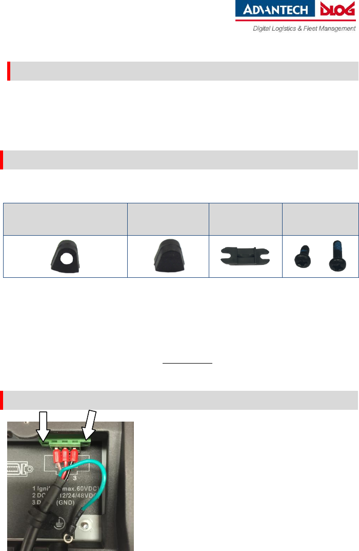
Cable sealing set (included in the scope of delivery)
Cable grommets
(which openings have different
sizes)
Dummy grommets
Cable clips
Mounting screws
Lay out all cables which are ready to be connected.
Check the cable diameters and cable elasticity as it will determine which cable grommet is the most
suitable (diameter of the opening).
IMPORTANT: The cable grommet must completely surround the cable.
The opening of the cable grommet must be slightly smaller than the cable diameter.
If the opening is too large or too small, the sealing of the device will not be ensured.
7.3 Plugging in and screwing on the power supply cable
Plug the power supply cable into the power
supply plug-in location.
Tighten both mounting screws hand-tight.
Fold-open the round cable passage in the
rubber seal.
Insert the power supply cable.
Quick Start Guide
DLT-V4108 Industrial PC
10 / 15
Quick Start Guide DLT-V4108, V001
DLoG GmbH, 2016
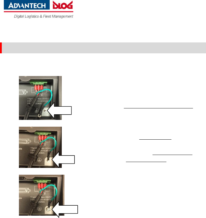
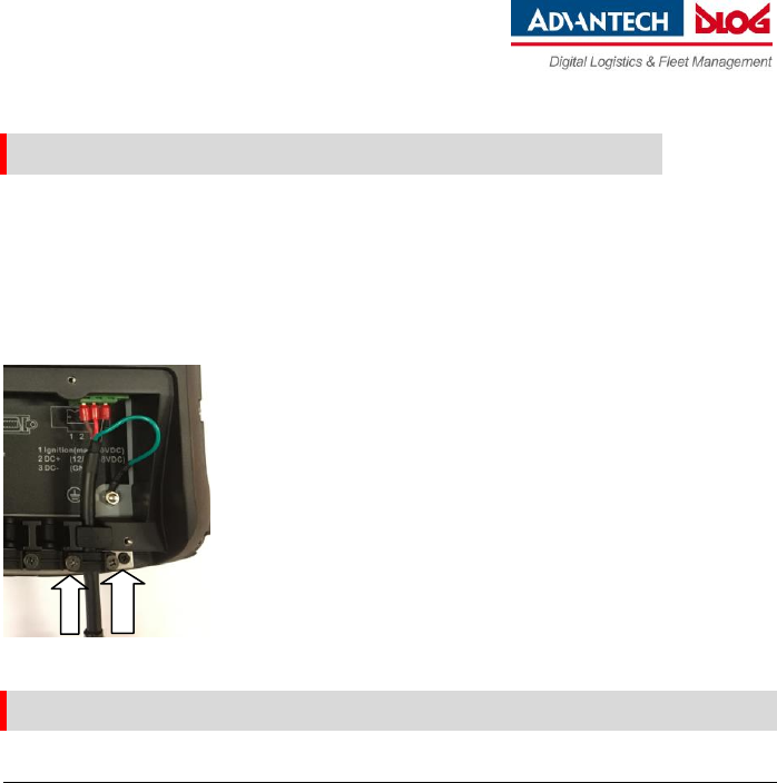
7.4 Securing the ground using ring tongue to the ground bolt
Secure the ring tongue of the power supply cable to the ground bolt:
ATTENTION
To make sure the device is grounding
correctly, it is important to follow the
correct order to put the components on
the ground bolt as below (from inside to
outside):
1. Place “toothed washer” first(internal)
2. Then put the “Ring Tongue of the
power supply cable” (flat side faces
DLT-V6210 connector panel)
3. Tightening the nut hand-tight.
1
2
3
Quick Start Guide
DLT-V4108 Industrial PC
DLoG GmbH, 2016
Quick Start Guide DLT-V4108, V001 PN:2005410820
11 / 15
7.5 Securing the power supply cable to the strain relief rail
Place one cable clip on the power supply cable.
Secure the cable clip to the strain relief rail using 2 mounting screws (M3x10 screws which in
accessory box).
Tighten the mounting screws alternatingly.
ATTENTION: Tighten the mounting screws sufficiently but on no account pinch or crush the
cable. If you do, the cables may break or the cable insulation may get damaged.
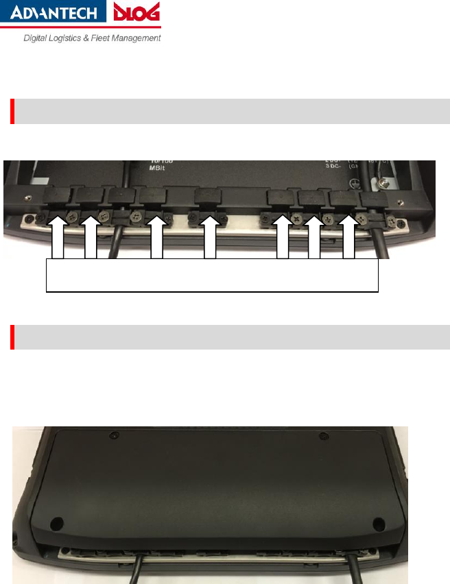
7.6 Connecting the USB, Ethernet, COM etc.
NOTICE: Physical damage
Only use accessories that have been tested and approved by Advantech-DLoG for DLT-V4108.
Proceed as described with the power supply cable:
Insert the cable.
Attach matching cable grommet.
Insert in the cable pass-through.
Secure to the strain relief rail using cable clip and screws.
Quick Start Guide
DLT-V4108 Industrial PC
12 / 15
Quick Start Guide DLT-V4108, V001
DLoG GmbH, 2016
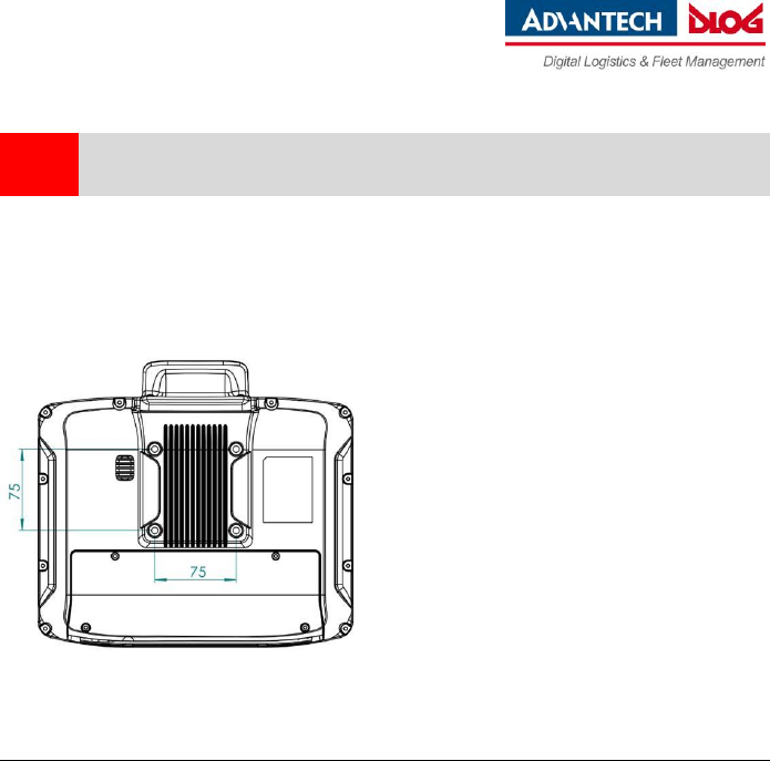
7.7 Closing off unused cable openings
Close off all unused cable pass-throughs with dummy grommets so that they are sealed.
7.8 Attaching the cable cover
Place the cable cover on DLT-V4108 housing slot.
Lock the M3x5 screws loosely into the holes of the cable cover.
Then fully tighten the screws alternatingly with 3 kgf-cm (0.294 nm) torque.
Dummy grommets
Quick Start Guide
DLT-V4108 Industrial PC
DLoG GmbH, 2016
Quick Start Guide DLT-V4108, V001 PN:2005410820
13 / 15
8
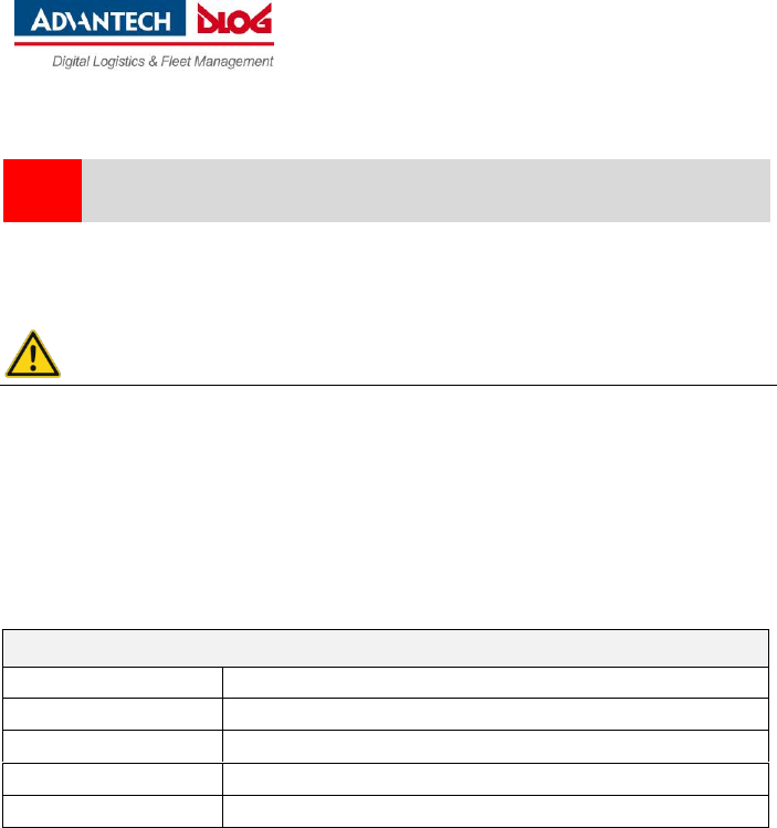
VESA-compatible drilling patterns
VESA-compatible drilling patterns for the RAM® attachment and swivel joint brackets are located on the
rear side of the DLT-V4108.
Depth of thread: M6 x 8 mm
NOTICE: Physical damage
Only use appropriate screws for fixing the RAM® attachment and swivel joint brackets to the
VESA drill holes: Depth of thread: M6 x 8 mm.
Use suitable mounting apparatus to avoid risk of injury
Quick Start Guide
DLT-V4108 Industrial PC
14 / 15
Quick Start Guide DLT-V4108, V001
DLoG GmbH, 2016
9
Integrated UPS and battery pack
The DLT-V4108 has an integrated uninterrupted power supply (UPS). The battery pack (lithium-ion
technology) of the UPS is located inside of back cover and couldn’t be changed by user.
WARNING
Personal injury due to short-circuit, fire, chemical burns, toxic substances.
The integrated UPS contain lithium-ion battery packs. These can ignite if the DLT-V4108 is handled or
stored improperly (risk of fire), cause chemical burns or release toxic substances.
Use care when handing the DLT-V4108.
Do not damage the DLT-V4108; otherwise lithium-ion battery packs could be damaged.
Do not allow the DLT-V4108 to come into contact with fire.
Performance specifications Li-ion rechargeable battery pack; 2 cells of UR14650R (900 mAh)
Bridging time
Typically 15 minutes (when battery pack is fully charged)
Charging time
2 h (fully recharge a completely discharged battery pack)
Charging temperature
0 ~ +45 °C (ambient temp.)
Output power
6.48 W
Battery voltage
7.2 V
Quick Start Guide
DLT-V4108 Industrial PC
DLoG GmbH, 2016
Quick Start Guide DLT-V4108, V001 PN:2005410820
15 / 15
10
Recycling information
DLT-V4108 devices that are no longer being used may not be
disposed of in the regular residential or domestic waste; they
must be taken to an official public collection point and handled by
a disposal provider.
Please contact the responsible authorities in your country/region
to find out about the applicable regulations for proper disposal, if
necessary.
11
Technical customer support
Please contact your distributor, your sales representative or Advantech-DLoG’s customer service to
receive technical support. Please have the following information available:
Product name, serial number
General description of the problem
Manufacturer address
DLoG GmbH, Industriestraße 15, D-82110 Germering
Email: helpdesk@advantech-dlog.com Web: www.advantech-dlog.com
Phone: +49 (0)89 / 41 11 91 999
Warranty
The Advantech-DLoG general terms and conditions of business are applicable to DLT-V4108 and its
accessories (Liability for defects -> limitation period for claims in relation to defects). For more details,
please refer to www.advantech-dlog.com.
by DLoG GmbH 2016. Information in this document is subject to change – also without prior notice.
DLoG GmbH assumes no liability for technical inaccuracies, typographic errors or faults in this document.
DLoG GmbH accepts no liability for damage caused directly or indirectly by the delivery, performance or
use of this document. RAM® and RAM Mount™ are both trademarks of National Products Inc., 1205 S. Orr
Street, Seattle, WA 98108. We recognize all national and international trademarks and product names.
Document finished on: 12/13/2016