Advantech Co EKI-1352 WLAN Serial Device Server User Manual V4 12 EA User Manual
Advantech Co Ltd WLAN Serial Device Server V4 12 EA User Manual
Contents
- 1. User manual 1 of 3
- 2. User manual 2 of 3
- 3. User manual 3 of 3
User manual 3 of 3
45 EKI-1351/EKI-1352/EKI-1521/1522/1524 User Manual
Chapter 3 Configuring Serial Device Server
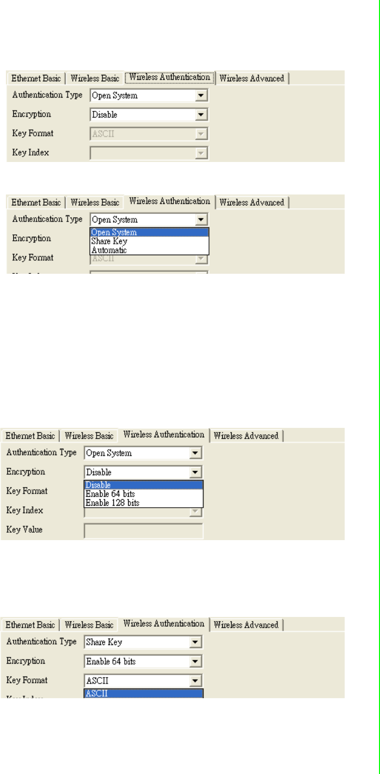
Authentication Type: There are three kinds of types in this drop-down menu
–Open system: No encryption for network communication. You can neglect the
key setting on the right side.
–WEP Share Key: Both communication devices use the same key as encryp-
tion.
–Automatic: Detect the WEP situation of the access point automatically. EKI-
1351 and EKI-1352 will use the current key for encryption. If EKI-1351/1352’s
key does not coincide with the access point’s key, the user should reset the
same key and reboot to connect.
Encryption: If the system needs WEP encryption, the user has to set the key
type. There are two kinds of encryption keys: 64 bits and 128 bits. For an open
system, the encryption function is disabled.
Set the key format. The table shows the allowed characters and length of the
different key index and key formats.
EKI-1351/EKI-1352/EKI-1521/1522/1524 User Manual 46
Index: This lists the supported encryption keys that you can choose from
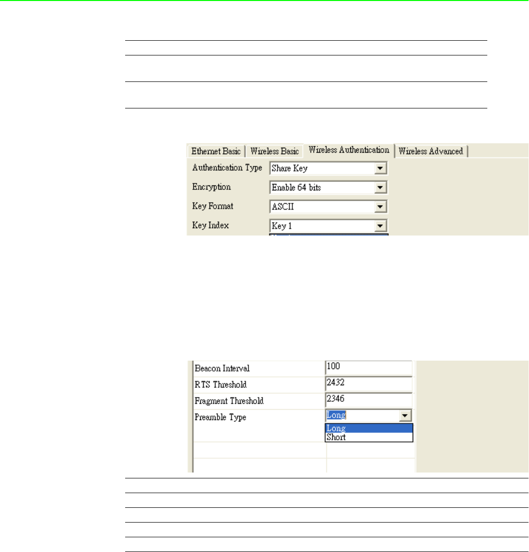
3.3.2.4 Wireless Advanced
The tab identifies several parameters that are related to the 802.11b/g wireless net-
work. We strongly suggested the default settings are not changed unless necessary.
If you want to recovery to factory value, you click the “Reset to factory default value”.
3.3.2.5 Beacon Interval
In infrastructure networks, the access point periodically sends beacons. You can set
the beacon interval with the access point configuration screen. In general, the bea-
con interval is set to 100 ms, which provides good performance for most applications.
In ad hoc networks, there are no access points. As a result, one of the peer stations
assumes the responsibility for sending the beacon. After receiving a beacon frame,
each station waits for the beacon interval and then sends a beacon if no other station
does so after a random time delay. This ensures that at least one station will send a
beacon, and the random delay rotates the responsibility for sending beacons.
Alphanumeric Hexadecimal
64 bits Up to 5 random characters
on the keyboard
Up to 10 random hexadecimal
characters (0 ~ 9, a ~ f)
128 bits Up to 13 random characters
on the keyboard
Up to 26 random hexadecimal
characters (0 ~ 9, a ~ f)
Parameters Default Value Range
Beacon Interval 100 0~65535
RTS Threshold 2347 0~2347
Fragment Threshold 2346 256~2346
Preamble Long Long/Short

47 EKI-1351/EKI-1352/EKI-1521/1522/1524 User Manual
Chapter 3 Configuring Serial Device Server
By increasing the beacon interval, you can reduce the number of beacons and asso-
ciated overhead, but that will likely delay the association and roaming process
because stations scanning for available access points may miss the beacons. You
can decrease the beacon interval, which increases the rate of beacons. This will
make the association and roaming process very responsive; however, the network
will incur additional overhead and throughput will go down. In addition, stations using
power save mode will need to consume more power because they’ll need to awaken
more often, which reduces power saving mode benefits.
3.3.2.6 RTS Threshold
RTS Threshold is the frame size above that an RTS/CTS handshake will be per-
formed before attempting to transmit. RTS/CTS ask for permission to transmit to
reduce collisions, but adds considerable overhead. Disabling RTS/CTS can reduce
overhead and latency in WLANs where all stations are close together, but can
increase collisions and degrade performance in WLANs where stations are far apart
and unable to sense each other to avoid collisions. If you are experiencing excessive
collisions, you can try turning RTS/CTS on or (if already on) reduce RTS/CTS
Threshold on the affected stations.
3.3.2.7 Fragmentation Threshold
Fragmentation Threshold is the maximum length of the frame, beyond which payload
must be broken up into two or more frames. Collisions occur more often for long
frames because sending them occupies the channel for a longer period of time,
increasing the chance that another station will transmit and cause a collision. Reduc-
ing Fragmentation Threshold results in shorter frames that "busy" the channel for
shorter periods, reducing packet error rate and resulting retransmissions. However,
shorter frames also increase overhead, degrading maximum possible throughput, so
adjusting this parameter means striking a good balance between error rate and
throughput.
3.3.2.8 Preamble
A preamble is a signal used in network communications to synchronize the transmis-
sion timing between two or more systems. Proper timing ensures that all systems are
interpreting the start of the information transfer correctly.
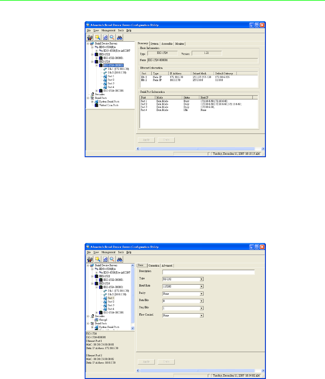
3.4 3.4 Setting serial parameters
This section explains how to configure Advantech serial device server serial
communication parameter using this utility. There are various operation modes that
are suitable for different application.
Click on the "+" before the model name (e.g. EKI-1522), and the utility will expand the
tree structure to show the individual device name. And click on the “+” before the
device name, and the utility will expand the interfaces on this device server. Select
the serial interface.
EKI-1351/EKI-1352/EKI-1521/1522/1524 User Manual 48
3.4.1 Setting serial port parameters
Click on the “+” before the device name, and the utility will expand the interfaces on
this device server. Select the one serial interface.
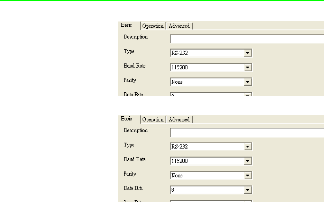
Description: You can give a more detailed description on the function of the port
for easier management and maintenance. Descriptions have a limit of 128 char-
acters.
49 EKI-1351/EKI-1352/EKI-1521/1522/1524 User Manual
Chapter 3 Configuring Serial Device Server
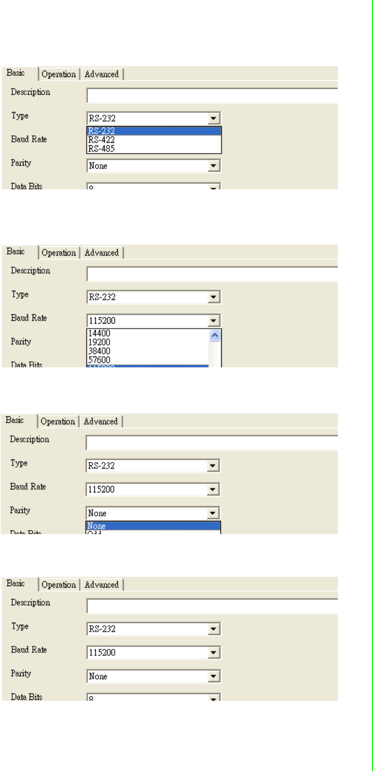
Type: The EKI serial device servers offer three kinds of serial protocols, RS-
232, RS-422 and RS-485. You can use any of the three serial protocols accord-
ing to your requirements.
Baud Rate: The EKI serial device servers support baud rates from 50 to
921.6Kbps. Total throughput up to 1.2M bps
Parity: The EKI serial device servers provide five options: None, Odd, Even,
Space, Mark.
Databit: The EKI serial device servers provide four options: 5, 6, 7 or 8.
EKI-1351/EKI-1352/EKI-1521/1522/1524 User Manual 50
Stopbits :The EKI serial device servers provide three options: 1, 1.5 or 2.
Flow Control: The EKI serial device servers provide four options: None, Xon/
Xoff, RTS/CTS, DTR/DSR.
3.4.2 Setting Virtual COM Operating Mode Parameters
The Advantech serial device servers extend traditional COM ports of a PC to Ether-
net access. Through Ethernet networking, users can control and monitor remote
serial devices and equipment over LAN or WAN. Advantech serial device servers
come with a COM port redirector (Virtual COM driver) that transmits all serial signals
intact. This means that your existing COM-based software can be preserved, without
modifying to fulfill the needs. The Virtual COM mode allows user to continue using
RS-232/422/485 serial communications software that was written for pure serial com-
munication applications.
EKI serial device servers come with COM port redirector(virtual COM driver) that
work with Window NT/2000/XP/Vista(X86) systems. The driver establishes a trans-
parent connection between host and serial device by mapping the IP of Advantech
serial device server serial port to a local COM port on the host computer.
EKI serial device server provides Multi-access function through one Ethernet
connection path or dual Ethernet connection path. Allow the max. of five connections
to open one serial port simultaneously. In the mode, all connection have to use the
same serial setting. If one serial setting of these connections is different from others,
the data communication may operate incorrectly.
51 EKI-1351/EKI-1352/EKI-1521/1522/1524 User Manual
Chapter 3 Configuring Serial Device Server
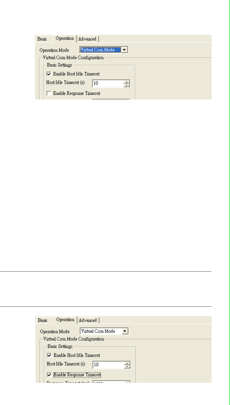
Host Idle Timeout: 10~255 second. The default vale is 10 second. The main
purpose of Host Idle timeout is when the idle happens and continues more than
the set value, the utility will cut off the connection between serial device servers
and the host automatically. You must re-connect to recover the communication.
EKI serial device server provides Multi-access function through one Ethernet
connection path or dual Ethernet connection path. Allow the max. of five connections
to open one serial port simultaneously. In the mode, all connection have to use the
same serial setting. If one serial setting of these connections is different from others,
the data communication may operate incorrectly.
There are two operating mode of Multi-access function. One is Normal mode;
another is Round-Robin mode.
Normal mode: disabling “Response Timeout” parameter, EKI serial device sev-
ers will operate in “normal mode”. When multiple hosts open the serial port
simultaneously, the EKI serial device server only offers control ability for the first
connected host and provides data communication function for others. Each
serial port supports up to five simultaneous connections, so multiple hosts can
transmit/receive data to/from the same serial port simultaneously. Every host
can transmit data to the same serial port, and EKI serial device server will also
transmit data to every hosts. When the multiple hosts transmit data to the same
serial port at the same time, the received data from Ethernet and the outputs of
serial port are mixed. When EKI serial device server receives data from serial
port, the data will also be transmitted to the connected hosts simultaneously.
Note This operating mode is especial suitable for that one major host send the
command and others hosts just listen the data from serial port. If two of con-
nected hosts send the command at the same time, it is possible that EKI
serial device server will not handle the command and will response the incor-
rect data.

EKI-1351/EKI-1352/EKI-1521/1522/1524 User Manual 52
Round-Robin mode: enabling “Response Timeout” parameter, the EKI serial
device servers will operate in “Round-Robin mode”. Each serial port supports up
to five simultaneous connections, so multiple hosts can transmit/receive data to/
from the same serial port simultaneously. Every host can transmit data to the
same serial port simultaneously, but EKI serial device server will process the
data communication in order. EKI serial device server will process the first
host’s request and reply the response to the first host. EKI serial device server
can determine the end of the serial acknowledgement via response timeout.
When EKI serial device server receives nothing from serial port after the setting
of response timeout, the device will reply the acknowledgement to the host and
then process the next host’s request. while the connected hosts are more and
“Response Timeout” is long, the process time is much longer.
Frame Break is a very import parameter for Round Robin mode. This parameter
is the smart way to reduce inefficient waiting time and EKI serial device server
can transmit data more efficiently. Disabling the Frame Break function, EKI
serial device server will wait “Response Timeout” period, whether the device
have transmitted the data. During this period, the commands from hosts will be
queued and EKI serial device server just processes this command. Enabling
“Frame Break”, if the serial port idle is longer than the “Frame Break” period, EKI
serial device server will assume the communication is completed and continue
the next host’s query. This is an efficient way to reduce the waiting time and
improve the performance.
Some of Advance Settings parameter is especial for Modbus/RTU communication. In
general, EKI serial device is suitable for Modbus/RTU protocol. If there is a communi-
cation issue between Modbus/RTU, you might try to set these parameters to fulfill the
Modbus/RTU needs.
Delay Time:<< not yet >>
Purge:<< not yet>>
Character Timeout Detection: << not yet>>
Multiple connections: Disabling multiple connections that this serial don’t sup-
port hosts mulit-Access.
3.4.3 Setting TCP/UDP Server operating mode parameters
EKI serial device server provides various operating mode. Select the operation
mode: USDG Mode to switch to TCP server/client or UDP mode. Before setting the
TCP server mode, you have to check the serial port setting first.

53 EKI-1351/EKI-1352/EKI-1521/1522/1524 User Manual
Chapter 3 Configuring Serial Device Server
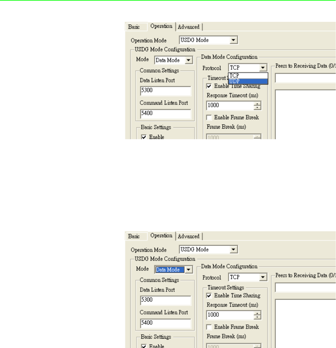
Data Mode: there are two major operation modes: Data Mode and Control
Mode. Using TCP server operating mode, you have to select Data Mode.
Data Listen Port: The port number represents the source port number, and the
number is used to identify the channel for remote initiating connections. Range:
1024-65533. If an unknown caller wants to connect to the system and asks for
some services, they need to define the port to carry a long-term conversation.
Each node on a TCP/IP network has an IP address, and each IP address can
allow connections on one or more TCP port. The well known TCP port are those
that have been defined; for example, port 23 is used for Telnet connections.
There are also custom sockets that users and developers define for their spe-
cific needs. Each port has its own data listen port to accept connected request
of other network device. So, the data listen port can’t be set the same value.
You can transmit/receive data to/from device via the data listen port.
Command Listen Port: Each port has its own command listen port to accept
connected request of other network device. So, the command listen port can’t
be set the same value. You can use ‘AT command’ to change the port setting
via the command listen port. The Command Listen Port must be different from
the Data Listen port.
Enable Data Idle Timeout: The default is 60 seconds. If you want to keep con-
nection continually, you might disable this function. Data idle Time is the time
period in which the device waits for data. If the EKI serial device server does not
receive data over an established idle time, the device server will disconnect
temporarily.
EKI-1351/EKI-1352/EKI-1521/1522/1524 User Manual 54
Protocol: TCP and UDP.
Enable Time sharing: this function is same as Mutli-Access function. Please
refer to the COM redirector setting.
3.4.4 Setting TCP/UDP Client operating mode parameters
EKI serial device server allows connecting to the hosts or other serial device servers,
EKI-135x Wireless modules allow maximum 4 connections. EKI-152x Ethernet
modules allow up to 16 connections simultaneously.
In order to enable this function, you just insert IP and TCP port number of the hosts
and other EKI serial device servers into the “Peers to Receiving Data”
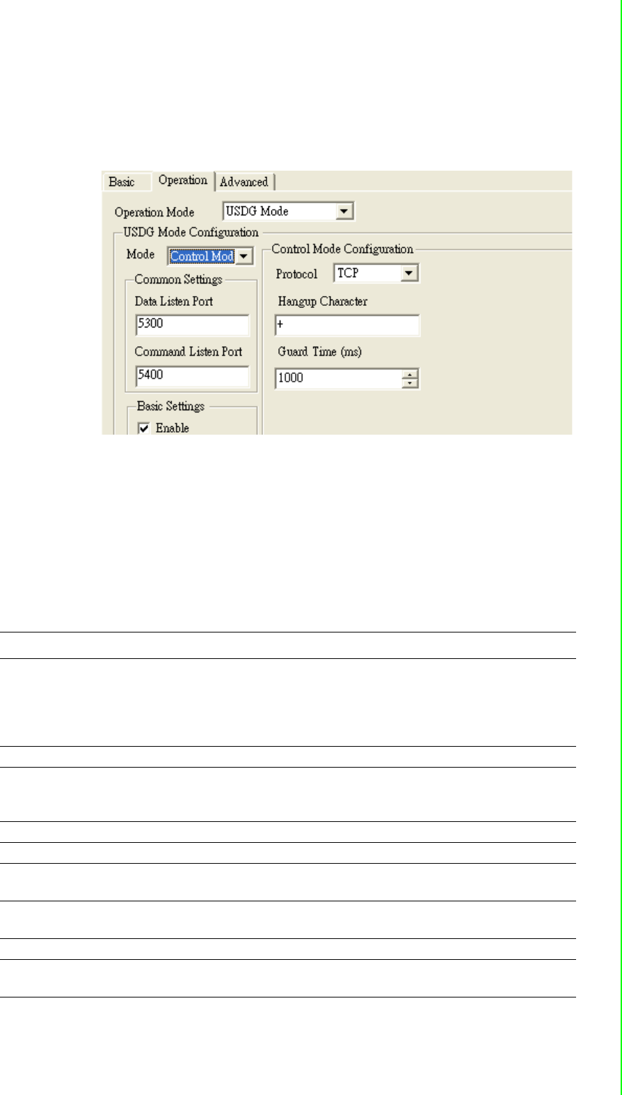
3.4.5 Setting Control operating mode parameters
The “Control mode” is a very special operating mode. The EKI serial device servers
present a modem interface to the attached serial device: it accepts AT-style modem
commands to connect / disconnect to other networking device. If you want serial
device running application program to connect/disconnect to different devices
dynamically, you can use controlling mode.
55 EKI-1351/EKI-1352/EKI-1521/1522/1524 User Manual
Chapter 3 Configuring Serial Device Server
The “Control mode” provides three modem AT-style commands. The serial devices
can use these commands to control EKI serial device server to connect/disconnect to
remote networking device. Thus, intelligent serial devices such as stand-alone PLC
will send /receive data to/from devices one by one via Ethernet.
Please refer to the TCP/UDP server operating mode to setup the Data Listen Port,
Command Listen Port, and Data Idle Timeout .
Hangup Character: the default character is “+”. While EKI serial device server
receive the character from serial port, the server cut off the connection.
Guard Time: the default value is 1000ms.
The following commands are available for EKI serial device severs.
Command Function
ATDT<IP address> <TCP port>
<CR>
“Forms a TCP connection to the specified host.
Ex: ATDT 192.0.55.22:5201
In above example, the EKI serial device server forms
a raw TCP connection to the networking device
(192.0.55.22). The TCP port is 5201.”
ATA <CR> Answering an incoming call
+++<CR> Returns the user to the command prompt when
entered from the serial port during a remote host con-
nection.
<LF><CR> OK <LF><CR> Commands are executed correctly
<LF><CR> CONNECT <LF><CR> Connect to other device
<LF><CR> RING ddd.ddd.ddd <LF><
CR>
Detect the connection request from other device,
which IP address is ddd.ddd.ddd.ddd.
<LF><CR> DISCONNECT
<LF><CR>
Disconnect from other device
<LF><CR> ERROR <LF><CR> Incorrect commands
<LF><CR> FAIL <LF><CR> If you issu an ATDT command and can not connect to
the device, it will response “FAIL”.

EKI-1351/EKI-1352/EKI-1521/1522/1524 User Manual 56
3.4.6 Setting Serial Tunneling Operation Mode Parameters
3.5 Running Diagnostic Test
3.5.1 Port Status Screen
3.5.2 Running Port Connection Test
3.5.3 Checking Wireless Status
3.6 Fulfilling Administrator Functions
3.6.1 Securing Access Clients
3.6.2 Setting Access Control
3.6.3 Upgrading Firmware

Chapter 4
4Setting COM
Redirector
EKI-1351/EKI-1352/EKI-1521/1522/1524 User Manual 58
4.1 Introduction
Advantech Configuration Utility also creates virtual COM ports that Windows applica-
tions will use to communicate with remote serial devices on the serial server. Advan-
tech virtual COM ports follow the same naming/numbering convention as Windows
COM ports.
4.2 EDG Favorite Groups
While you move the device(s) to the Favorite Group, you can use these functions
Update firmware
Auto Mapping
Manual Mapping
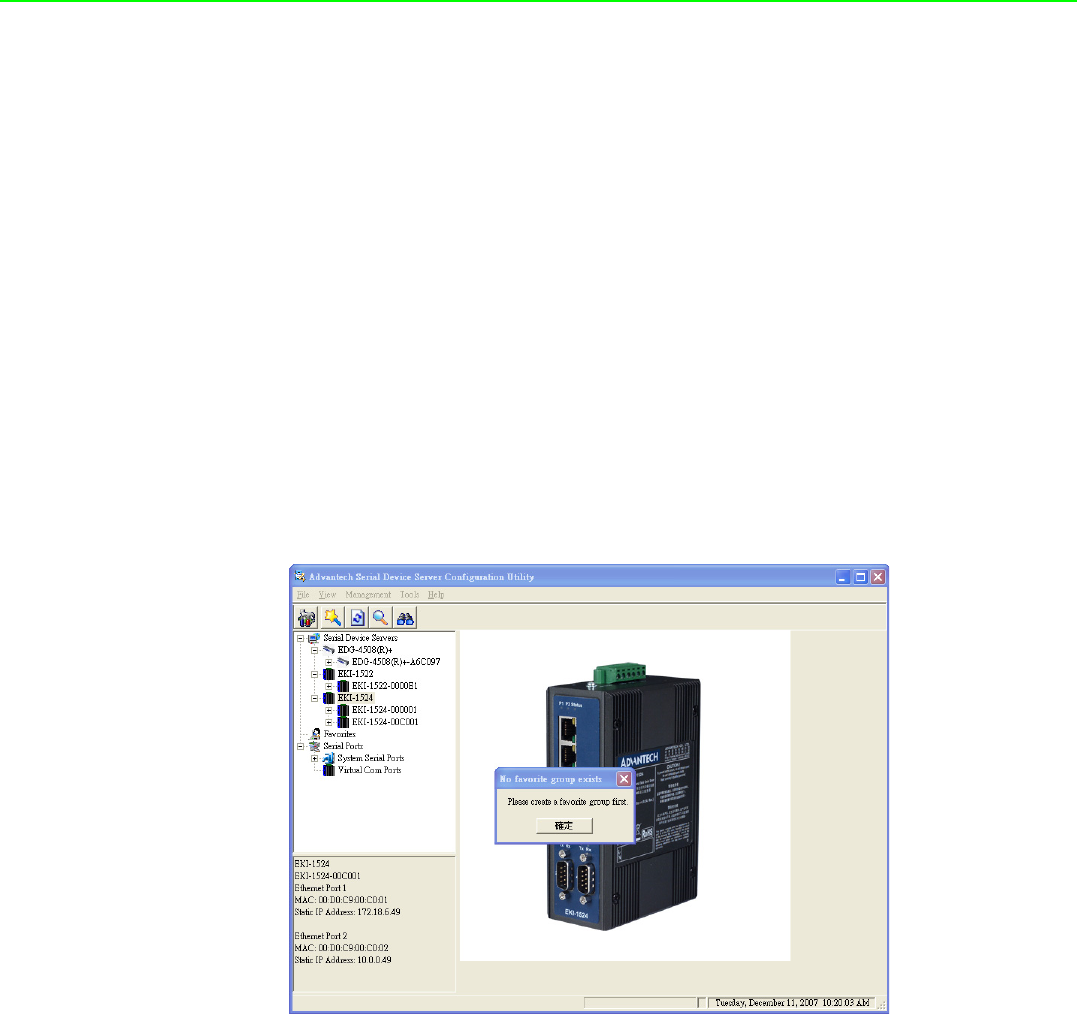
4.2.1 Creating Favorite group
You have to create at least one favorite group in EDG device Favorites; otherwise,
utility will discard the adding and show this warming message.
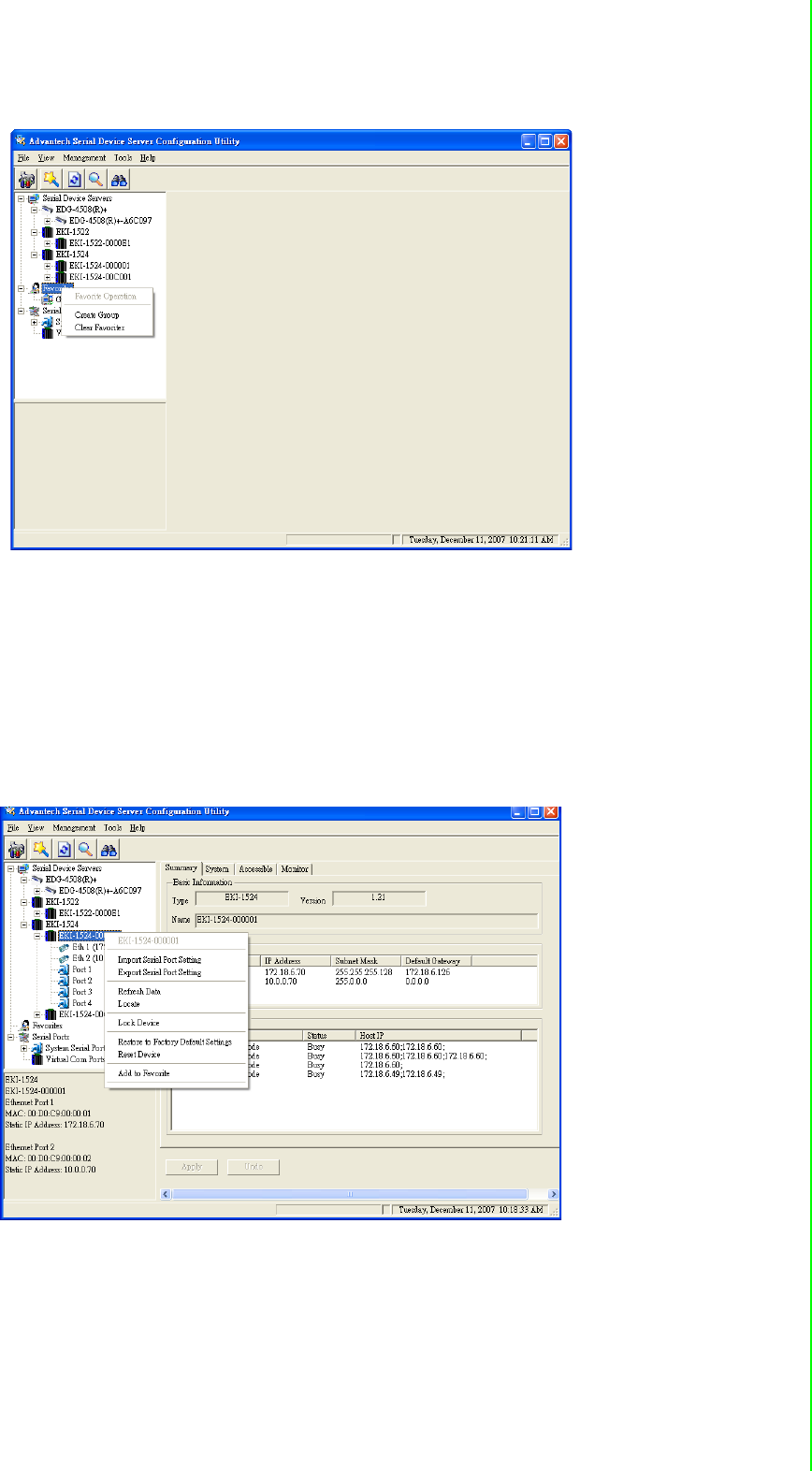
59 EKI-1351/EKI-1352/EKI-1521/1522/1524 User Manual
Chapter 4 Setting COM Redirector
After creating favorite group, you can select the device and hold the mouse button to
move this device to the group. Or select the device and right click the muse button
and select “Add to Favorite”
The device server are grouped in EDG Device Favorites can setup the Virtual COM
and upgrade the firmware.
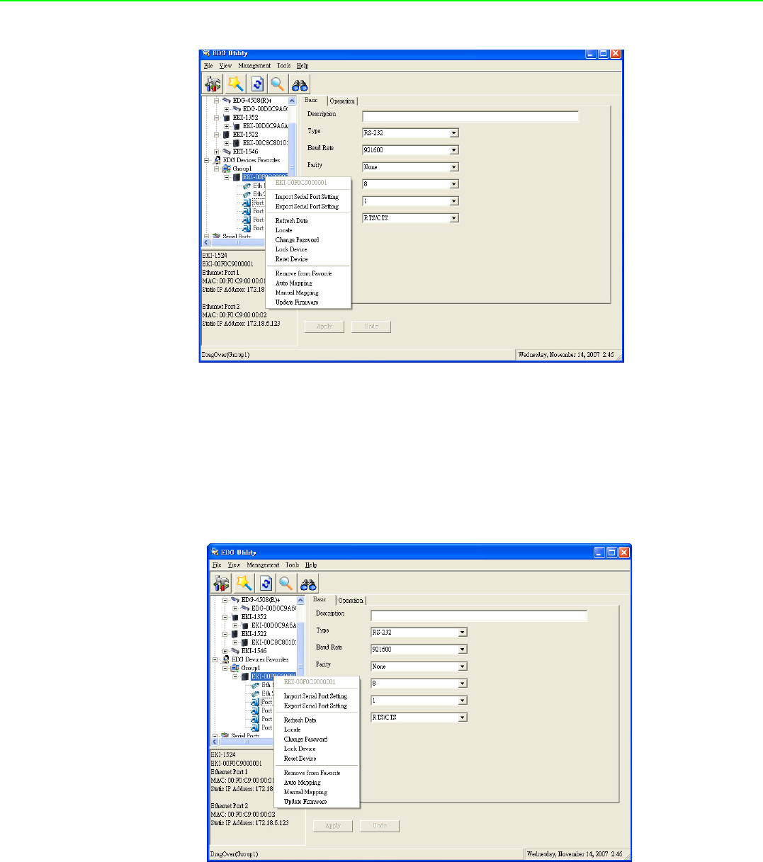
EKI-1351/EKI-1352/EKI-1521/1522/1524 User Manual 60
4.2.2 4.1.2 Removing device server from Favorite group
Select the device and right click the muse button and select “Remove from Favorite”
61 EKI-1351/EKI-1352/EKI-1521/1522/1524 User Manual
Chapter 4 Setting COM Redirector
4.3 Setting COM Redirector(Virtual COM port)
Advantech COM port mapping software is a serial COM port redirector that creates
virtual COM ports and provides access to serial devices connected to Advantech
serial device servers. Your serial device applications can communicate with serial
devices connected to Advantech serial device servers without software changes.
Since the virtual COM ports work like standard Windows COM ports, your application
software sees no difference between a local serial device and one connected to a
Advantech serial device server.
COM redirector utility and Virtual COM port Management utility are integrated into
one utility with same GUI. Before your establish Virtual COM port pool, you have to
create the EDG Device Favorites group and move your device server into these
groups. Virtual COM port Management utility can create all Virtual COM ports using
“Auto Mapping” function. You can map the Virtual COM port by yourself.
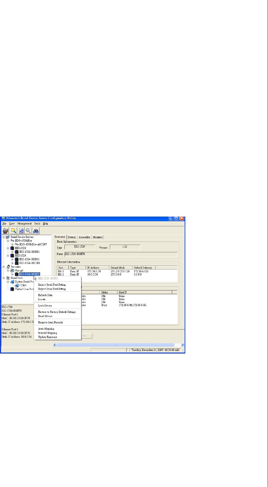
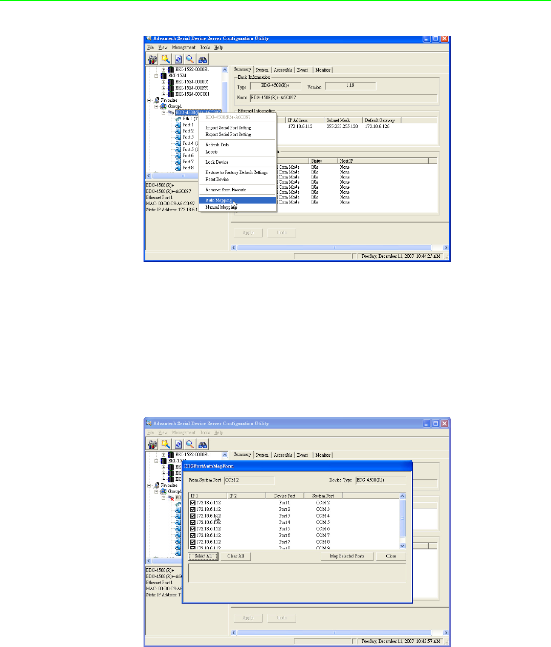
4.3.1 Auto Mapping
Right click the serial device on the Favorite group and select the “Auto Mapping”
function.
EKI-1351/EKI-1352/EKI-1521/1522/1524 User Manual 62
The serial ports that can be assigned to virtual COM will be shown in this window.
Select the serial ports you wish to map or click the <Select All> button and press
<Map Selected Port> button.The selected serial ports will be mapped to virtual COM
ports in sequential order.
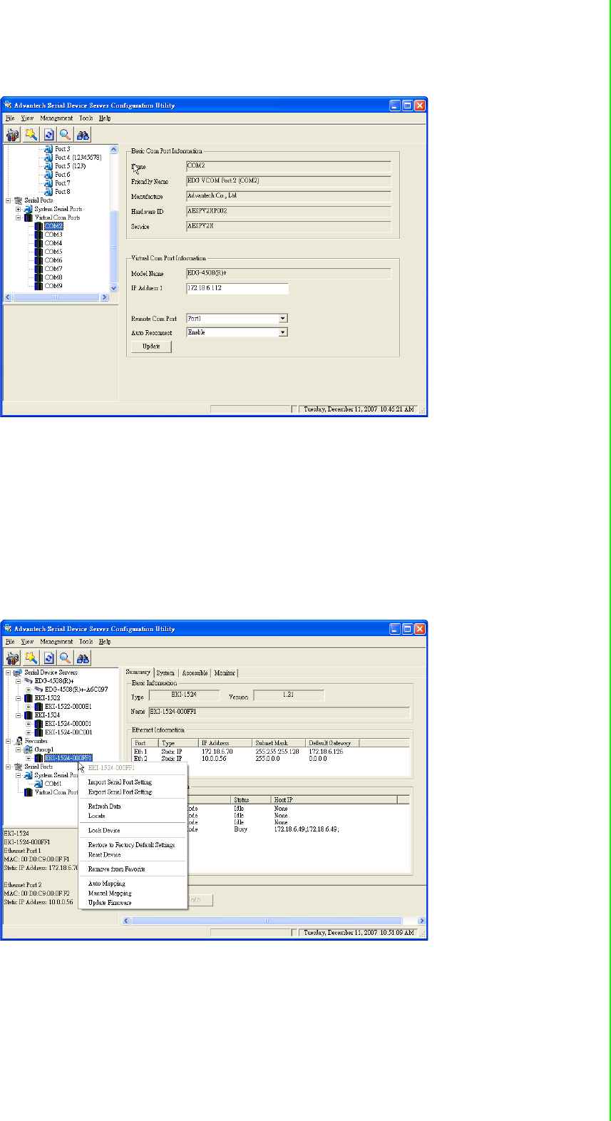
The COM ports in the ‘EDG Serial port’ listing are now available for use by Windows
applications.
63 EKI-1351/EKI-1352/EKI-1521/1522/1524 User Manual
Chapter 4 Setting COM Redirector
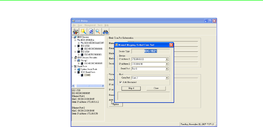
4.3.2 Manual Mapping
Right click the serial device on the Favorite group and select the “Manual Mapping”
function.
ADAM series, EDG series, and EKI wireless series have only one IP address. You
select the serial port on the device server and the host COM that you want to set.
Press <Map it> to establish the virtual COM port on the host.
EKI-1351/EKI-1352/EKI-1521/1522/1524 User Manual 64
4.3.2.1 Auto Reconnect property
Sometimes, the connection between EDG device and HOST is interrupted by net-
work traffic or powered-off by accident. In such a situation, the host have to recon-
nect to Advantech serial device server. The function "Auto-reconnect" is for this
purpose, If the Advantech serial server loses the connection to its host, the COM
redirector will try to re-establish the connection while the host AP access the virtual
COM port. The COM redirector DO NOT re-establish the connection automatically.
When the connection is working again, the host's commands will be automatically
received by the Advantech serial device server again. Reconfiguration is not neces-
sary, so this function enhances the reliability of the system.
if the function is disabled, the connection can not be re-established again unless the
COM redirector or host is restarted.
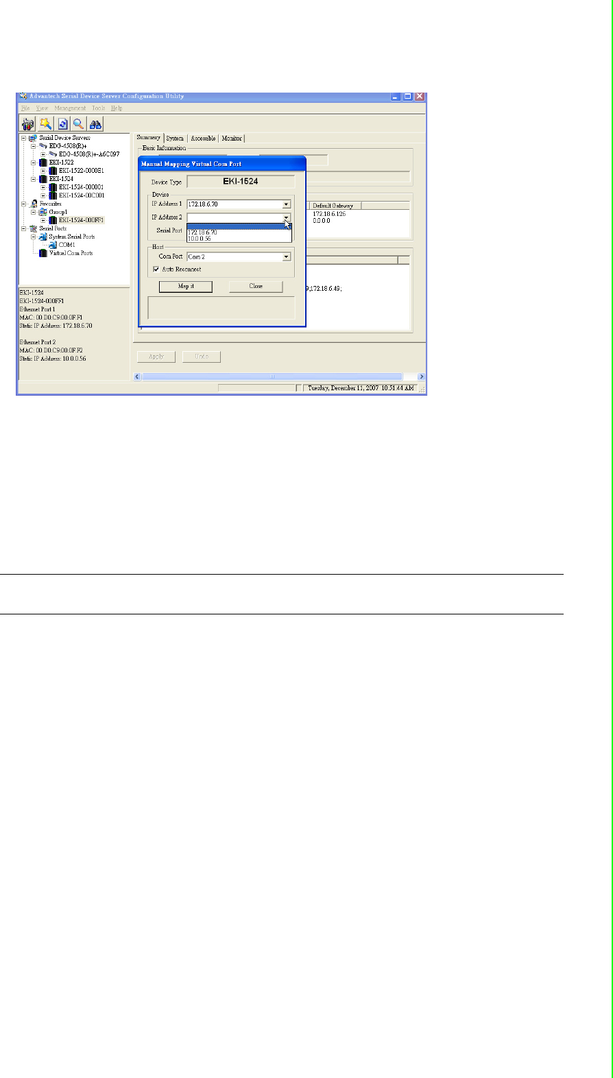
EKI-1521, EKI-1522, and EKI-1524 have two Ethernet ports. You can select two
Ethernet port to establish two Ethernet connections with one virtual COM port. It
means that COM redirector will use one connection with the COM port on device
server to communicate. If this connection failed, COM redirector will establish
another Ethernet connection to communicate with device. The switch time will be 3
second ~ 5 second depending on the network traffic and host status.
65 EKI-1351/EKI-1352/EKI-1521/1522/1524 User Manual
Chapter 4 Setting COM Redirector
If you don’t use the redundant function, you just select the correct IP address in the
IP address 1 field.
Note if you set the wrong IP address, COM redirector will still try to connect the
device. It might cause the system performance low or other issue.

www.advantech.com
Please verify specifications before quoting. This guide is intended for reference
purposes only.
All product specifications are subject to change without notice.
No part of this publication may be reproduced in any form or by any means,
electronic, photocopying, recording or otherwise, without prior written permis-
sion of the publisher.
All brand and product names are trademarks or registered trademarks of their
respective companies.
© Advantech Co., Ltd. 2007