Advantech Co EKI-1352 WLAN Serial Device Server User Manual V4 12 EA User Manual
Advantech Co Ltd WLAN Serial Device Server V4 12 EA User Manual
Contents
- 1. User manual 1 of 3
- 2. User manual 2 of 3
- 3. User manual 3 of 3
User manual 1 of 3
User Manual
EKI-1351/1352/EKI-1521/1522/1524
1/2/4-port RS-232/422/485 Serial
Device Servers

EKI-1351/EKI-1352/EKI-1521/1522/1524 User Manual ii
Copyright
The documentation and the software included with this product are copyrighted 2006
by Advantech Co., Ltd. All rights are reserved. Advantech Co., Ltd. reserves the right
to make improvements in the products described in this manual at any time without
notice. No part of this manual may be reproduced, copied, translated or transmitted
in any form or by any means without the prior written permission of Advantech Co.,
Ltd. Information provided in this manual is intended to be accurate and reliable. How-
ever, Advantech Co., Ltd. assumes no responsibility for its use, nor for any infringe-
ments of the rights of third parties, which may result from its use.
Acknowledgements
Intel and Pentium are trademarks of Intel Corporation.
Microsoft Windows and MS-DOS are registered trademarks of Microsoft Corp.
All other product names or trademarks are properties of their respective owners.
Product Warranty (2 years)
Advantech warrants to you, the original purchaser, that each of its products will be
free from defects in materials and workmanship for two years from the date of pur-
chase.
This warranty does not apply to any products which have been repaired or altered by
persons other than repair personnel authorized by Advantech, or which have been
subject to misuse, abuse, accident or improper installation. Advantech assumes no
liability under the terms of this warranty as a consequence of such events.
Because of Advantech’s high quality-control standards and rigorous testing, most of
our customers never need to use our repair service. If an Advantech product is defec-
tive, it will be repaired or replaced at no charge during the warranty period. For out-
of-warranty repairs, you will be billed according to the cost of replacement materials,
service time and freight. Please consult your dealer for more details.
If you think you have a defective product, follow these steps:
1. Collect all the information about the problem encountered. (For example, CPU
speed, Advantech products used, other hardware and software used, etc.) Note
anything abnormal and list any onscreen messages you get when the problem
occurs.
2. Call your dealer and describe the problem. Please have your manual, product,
and any helpful information readily available.
3. If your product is diagnosed as defective, obtain an RMA (return merchandize
authorization) number from your dealer. This allows us to process your return
more quickly.
4. Carefully pack the defective product, a fully-completed Repair and Replacement
Order Card and a photocopy proof of purchase date (such as your sales receipt)
in a shippable container. A product returned without proof of the purchase date
is not eligible for warranty service.
5. Write the RMA number visibly on the outside of the package and ship it prepaid
to your dealer.
Part No. 2003152100 Edition 1
Printed in Taiwan January 2008

iii EKI-1351/EKI-1352/EKI-1521/1522/1524 User Manual
Declaration of Conformity
CE
This product has passed the CE test for environmental specifications when shielded cables are used for
external wiring. We recommend the use of shielded cables. This kind of cable is available from Advantech.
Please contact your local supplier for ordering information.
CE
This product has passed the CE test for environmental specifications. Test conditions for passing included
the equipment being operated within an industrial enclosure. In order to protect the product from being
damaged by ESD (Electrostatic Discharge) and EMI leakage, we strongly recommend the use of CE-
compliant industrial enclosure products.
FCC
This equipment has been tested and found to comply with the limits for a Class B digital device, pursuant to
part 15 of the FCC rules. These limits are designed to provide reasonable protection against harmful
interference in a residential installation. This equipment generates, uses and can radiate radio frequency
energy and, if not installed and used in accordance with the instructions, may cause harmful interference to
radio communications. However, there is no guarantee that interference will not occur in a particular
installation. If this equipment does cause harmful interference to radio or television reception, which can be
determined by turning the equipment off and on, the user is encouraged to try to correct the interference by
one or more of the following measures:
-Reorient or relocate the receiving antenna.
-Increase the separation between the equipment and receiver.
-Connect the equipment into an outlet on a circuit different from
that to which the receiver is connected.
-Consult the dealer or an experienced radio/TV technician for help.
You are cautioned that changes or modifications not expressly
approved by the party responsible for compliance could void your
authority to operate the equipment.
FCC RF Radiation Exposure Statement: 1. This Transmitter must
not be co-located or operating in conjunction with any other antenna
or transmitter. 2. This equipment complies with FCC RF radiation
exposure limits set forth for an uncontrolled environment. This equipment
should be installed and operated with a minimum distance of 20
centimeters between the radiator and your body.
Technical Support and Assistance
1. Visit the Advantech web site at www.advantech.com/support where you can find
the latest information about the product.
2. Contact your distributor, sales representative, or Advantech's customer service
center for technical support if you need additional assistance. Please have the
following information ready before you call:
– Product name and serial number
– Description of your peripheral attachments
– Description of your software (operating system, version, application software,
etc.)
– A complete description of the problem
– The exact wording of any error messages

EKI-1351/EKI-1352/EKI-1521/1522/1524 User Manual iv
Safety Instructions
1. Read these safety instructions carefully.
2. Keep this User Manual for later reference.
3. Disconnect this equipment from any AC outlet before cleaning. Use a damp cloth. Do not use liquid
or spray detergents for cleaning.
4. For plug-in equipment, the power outlet socket must be located near the equipment and must be
easily accessible.
5. Keep this equipment away from humidity.
6. Put this equipment on a reliable surface during installation. Dropping it or letting it fall may cause
damage.
7. The openings on the enclosure are for air convection. Protect the equipment from overheating. DO
NOT COVER THE OPENINGS.
8. Make sure the voltage of the power source is correct before connecting the equipment to the power
outlet.
9. Position the power cord so that people cannot step on it. Do not place anything over the power cord.
10. All cautions and warnings on the equipment should be noted.
11. If the equipment is not used for a long time, disconnect it from the power source
to avoid damage by transient overvoltage.
12. Never pour any liquid into an opening. This may cause fire or electrical shock.
13. Never open the equipment. For safety reasons, the equipment should be
opened only by qualified service personnel.
14. If one of the following situations arises, get the equipment checked by service
personnel:
15. The power cord or plug is damaged.
16. Liquid has penetrated into the equipment.
17. The equipment has been exposed to moisture.
18. The equipment does not work well, or you cannot get it to work according to the
user's manual.
19. The equipment has been dropped and damaged.
20. The equipment has obvious signs of breakage.
21. DO NOT LEAVE THIS EQUIPMENT IN AN ENVIRONMENT WHERE THE
STORAGE TEMPERATURE MAY GO BELOW -20° C (-4° F) OR ABOVE 60° C
(140° F). THIS COULD DAMAGE THE EQUIPMENT. THE EQUIPMENT
SHOULD BE IN A CONTROLLED ENVIRONMENT.
22. CAUTION: DANGER OF EXPLOSION IF BATTERY IS INCORRECTLY
REPLACED. REPLACE ONLY WITH THE SAME OR EQUIVALENT TYPE
RECOMMENDED BY THE MANUFACTURER, DISCARD USED BATTERIES
ACCORDING TO THE MANUFACTURER'S INSTRUCTIONS.
23. The sound pressure level at the operator's position according to IEC 704-1:1982
is no more than 70 dB (A).
DISCLAIMER: This set of instructions is given according to IEC 704-1. Advantech
disclaims all responsibility for the accuracy of any statements contained herein.
Safety Precaution - Static Electricity
Follow these simple precautions to protect yourself from harm and the products from
damage.
To avoid electrical shock, always disconnect the power from your PC chassis
before you work on it. Don't touch any components on the CPU card or other
cards while the PC is on.
Disconnect power before making any configuration changes. The sudden rush
of power as you connect a jumper or install a card may damage sensitive electronic
components.

v EKI-1351/EKI-1352/EKI-1521/1522/1524 User Manual
Contents
1.1 Introduction ............................................................................................... 2
1.2 Features .................................................................................................... 3
1.2.1 1.2.1 EKI-1521, EKI-1522, and EKI-1524 ..................................... 3
1.2.2 1.2.2 EKI-1351 and EKI-1352 ....................................................... 3
1.3 Specifications ............................................................................................ 4
1.3.1 EKI-1521, EKI-1522 and EKI-1524 ............................................... 4
1.3.2 1.3.2 EKI-1351, EKI-1352 ............................................................. 5
1.4 1.4 Package Check List ............................................................................ 5
Chapter 2 Getting Started.....................................7
2.1 Understanding Serial Device Servers ....................................................... 8
2.1.1 Product Description....................................................................... 8
2.1.2 COM port redirector (Virtual COM port) ........................................ 9
2.1.3 TCP Server Mode ....................................................................... 11
2.1.4 TCP Client Mode......................................................................... 12
2.1.5 Serial Tunneling mode ................................................................ 13
2.1.6 UDP Server/Client Mode............................................................. 13
2.1.7 Control Mode .............................................................................. 14
2.2 Hardware................................................................................................. 14
2.2.1 LED Indicators ............................................................................ 14
2.2.2 Dimension (units:mm) ................................................................. 16
Figure 2.1 Front View ................................................................ 16
Figure 2.2 Side View.................................................................. 16
Figure 2.3 Back View................................................................. 17
Figure 2.4 Top View................................................................... 17
Figure 2.5 Front View ................................................................ 18
Figure 2.6 Side View.................................................................. 18
Figure 2.7 Back View................................................................. 19
Figure 2.8 Top View................................................................... 19
Figure 2.9 Front View ................................................................ 20
Figure 2.10Side View.................................................................. 20
Figure 2.11Back View................................................................. 21
Figure 2.12Top View................................................................... 21
2.3 Connecting Hardward ............................................................................. 22
2.3.1 Choosing a Location ................................................................... 22
Figure 2.13Combining the Metal Mounting Kit............................ 22
Figure 2.14DIN-rail Step 1 .......................................................... 23
Figure 2.15DIN-rail Step 2 .......................................................... 23
2.3.2 Network Connection.................................................................... 23
2.3.3 Wireless Connection .................................................................. 24
2.3.4 Power Connection....................................................................... 24
2.3.5 Serial Connection........................................................................ 25
2.4 Configuration Utility installation ............................................................... 25
Chapter 3 Configuring Serial Device Server.....31
3.1 Configuration Utility Overview ................................................................ 32
3.2 Discovering Serial Device Servers.......................................................... 36
3.2.1 Auto Searching .......................................................................... 36
3.2.2 Manual Appending ...................................................................... 40
3.3 Setting network parameters .................................................................... 41
3.3.1 Setting TCP/IP(LAN) parameters................................................ 41
3.3.2 Setting Wi-Fi(Wireless) parameters ............................................ 41

EKI-1351/EKI-1352/EKI-1521/1522/1524 User Manual vi
3.4 3.4 Setting serial parameters .................................................................. 47
3.4.1 Setting serial port parameters..................................................... 48
3.4.2 Setting Virtual COM Operating Mode Parameters...................... 50
3.4.3 Setting TCP/UDP Server operating mode parameters ............... 52
3.4.4 Setting TCP/UDP Client operating mode parameters ................ 54
3.4.5 Setting Control operating mode parameters............................... 54
3.4.6 Setting Serial Tunneling Operation Mode Parameters ............... 56
3.5 Running Diagnostic Test......................................................................... 56
3.5.1 Port Status Screen...................................................................... 56
3.5.2 Running Port Connection Test.................................................... 56
3.5.3 Checking Wireless Status........................................................... 56
3.6 Fulfilling Administrator Functions ............................................................ 56
3.6.1 Securing Access Clients ............................................................ 56
3.6.2 Setting Access Control ............................................................... 56
3.6.3 Upgrading Firmware ................................................................... 56
Chapter 4 Setting COM Redirector ................... 57
4.1 Introduction ............................................................................................. 58
4.2 EDG Favorite Groups ............................................................................. 58
4.2.1 Creating Favorite group .............................................................. 58
4.2.2 4.1.2 Removing device server from Favorite group.................... 60
4.3 Setting COM Redirector(Virtual COM port)............................................. 61
4.3.1 Auto Mapping.............................................................................. 61
4.3.2 Manual Mapping ......................................................................... 63

Chapter 1
Overview
\

EKI-1351/EKI-1352/EKI-1521/1522/1524 User Manual 2
1.1 Introduction
Advantech’s EKI series of Industrial Device Servers are robust, feature-rich, and cost
effective way to network-enable equipment in an industrial automation environment.
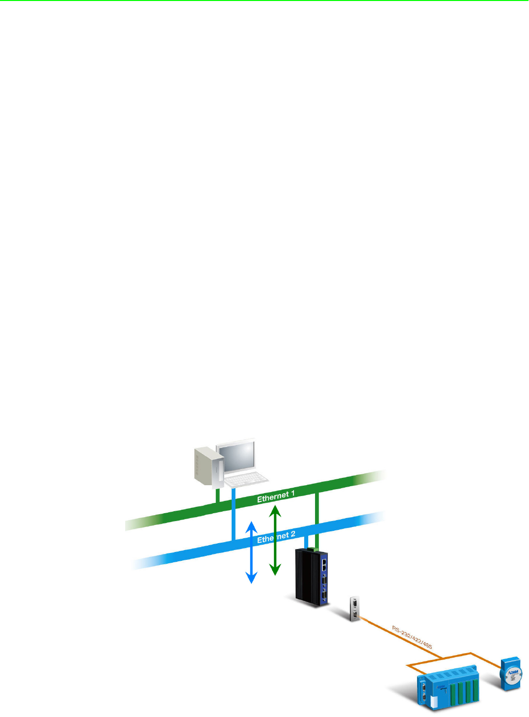
The EKI-1521, EKI-1522 and EKI-1524 provide 1/2/4 serial ports, two switched
Ethernet ports, a wide power input range, and compact slim design, making it an
ideal solution for connecting multiple asynchronous RS232, RS422, or RS485 serial
devices to an Ethernet network.
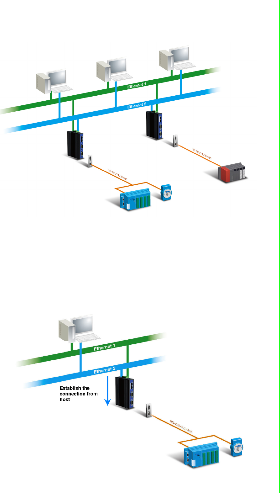
The two Ethernet ports allow the EKI serial device server to establish two separate
Ethernet connections to two Ethernet domain or two Ethernet Switches in the same
domain. By dual Ethernet connection, the EKI serial device servers greatly improve
the device connectivity reliability, increase system stability, and simplify the redun-
dant configuration.
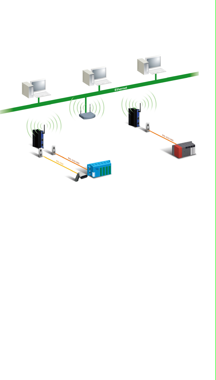
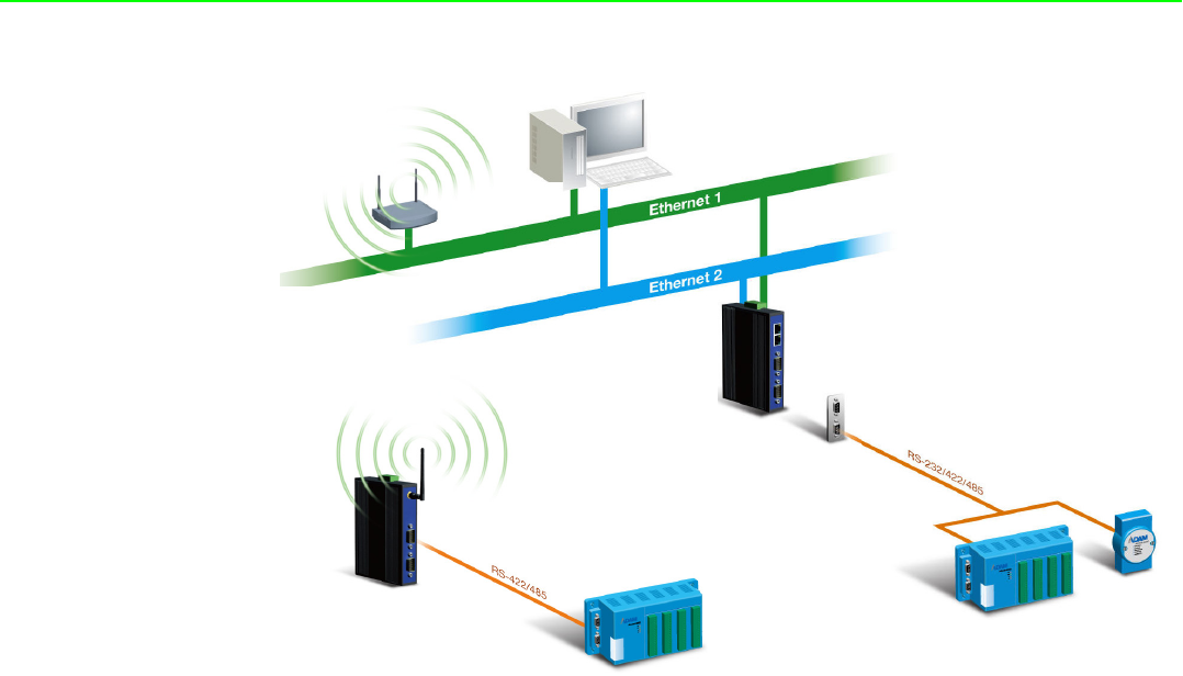
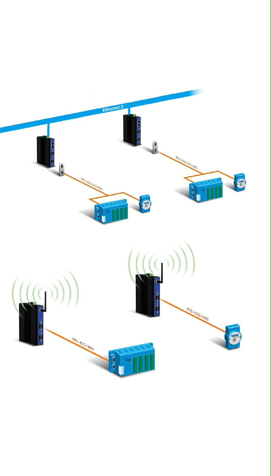
The EKI-1351, and EKI-1352 provide 1/2 serial ports, 802.11b/g Wireless LAN inter-
face to connect any RS-232/422/485 devices to Wireless LAN. These wireless serial
device servers provide serial-to-wireless network connectivity as an alternative to
wired Ethernet connectivity and enable virtually any serial device or equipment to be
remotely accessed, controlled, monitored, or shared on an 802.11b/g wireless net-
work.
By encapsulating serial data and transporting it over Ethernet, the EKI serial device
servers allow virtual serial links over Ethernet and IP (TCP/IP, UDP/IP) networks.
After Advantech COM redirection software installation, standard serial operation calls
are transparently redirected to the EKI serial device servers, guaranteeing compati-
bility with legacy serial devices and enabling backward compatibility with existing
software. EKI serial device servers also support serial tunneling, allowing two native
serial devices to communicate over a network without any hosts and programming.
As a result, you can extend limited distance, point-to-point, direct serial connections
within the plant, throughout the factory, the facility, the office building, or across the
global enterprise.
The EKI serial device server provide an impressive list of features and functions
enabling multiple industrial devices to be connected, controlled, configured, man-
aged, and updated over a network. With serial ports ,two auto-sensing Ethernet ports
or 802.11b/g Wireless , the EKI serial device servers can easily connect multiple
serial devices to a network.
The transmission speed of the EKI serial device servers is up to 1.2M bps totally out-
stripping the competition to meet the demand for high-speed exchange. Functionally
transparent and efficient, the EKI serial device server is especially designed for
remotely controlling and monitoring devices via the Internet.
Type of supported devices:
Human Machine Interface (HMI)
Programmable Controller(PLC)
Flow meters
Temperature / pressure monitoring equipment
Gas leak detection device
Scales
Power monitoring equipment
Data Acquisition Modules
EKI serial device servers provide various TCP/UDP operations: COM port redirection
(Virtual COM port), TCP server/ client and UDP mode. Serial devices can be
connected by means of multi-operation modes.

3 EKI-1351/EKI-1352/EKI-1521/1522/1524 User Manual
Chapter 1
1.2 Features
1.2.1 1.2.1 EKI-1521, EKI-1522, and EKI-1524
Expand up 255 serial ports for one Windows NT/2000/XP/Vista(X86) host
Provides dual 10/100 Base-T auto-sensing Ethernet ports: establish two
separate Ethernet connection.
Supports high transmission speed up to 1.2M bps totally
Supports various operation mode: COM port redirection (Virtual COM port),
TCP server/client, UDP server/client mode.
Supports LED indicators: easy to diagnostic
Supports integrated Configuration utility and port-mapping utility: easy to
configure and manage 255 COM ports and self-diagnostic.
Support great multi-access feature: allow a max 5 of hosts’ access one serial
port simultaneously.
Allows a max 16 hosts to access TCP client and command response mode.
Easy to locate specific EKI serial device server.
Mounts on DIN rail, or panel easily.
1.2.2 1.2.2 EKI-1351 and EKI-1352
Expand up 255 serial ports for one Windows NT/2000/XP/Vista(X86) host
Provides 802.11b/g standard.
Supports Wireless LAN Ad-Hoc and Infrastructure modes
Supports high transmission speed up to 1.2M bps totally
Supports various operation mode: COM port redirection (Virtual COM port),
TCP server/client, UDP server/client mode.
Supports LED indicators: easy to diagnostic
Supports integrated Configuration utility and port-mapping utility: easy to
configure and manage 255 COM ports and self-diagnostic.
Support great multi-access feature: allow a max 5 of hosts’ access one serial
port simultaneously.
Allows a max 4 hosts to access TCP client and command response mode.
Easy to locate specific EKI serial device server.
Mounts on DIN rail, or panel easily.

EKI-1351/EKI-1352/EKI-1521/1522/1524 User Manual 4
1.3 Specifications
1.3.1 EKI-1521, EKI-1522 and EKI-1524
Ethernet communication compatibility: IEEE802.3, IEEE802.3u
Protocol: TCP/IP
Interface:
Network: 2 x 10/100Base-T auto-sensing
Serial: RS-232/422/485
Serial ports: 1/2/4 independent RS-232/422/485 ports
EKI-1521: 1 x RS-232/422/485 port
EKI-1522: 2 x RS-232/422/485 port
EKI-1524: 4 x RS-232/422/485 port
Connector
Network: RJ-45
Serial: DB9
Baud rate: 50~ 921kbps
Throughput:
Total throughput up to 1.2M bps
Parity bit: odd, even, none, space, mark
Data bit: 5, 6, 7, 8
Stop bit: 1, 1.5, 2
Data Signals: RS-232: TxD, RxD, CTS, RTS, DTR, DSR, DCD, RI, GND
RS-422: TxD+, TxD-, RxD+, RxD-, GND
RS-485: Data+, Data-, GND
Diagnostic LEDs: Power, Status, Ethernet Tx/Rx and Serial Tx/Rx
Utility Software: Integrated auto-detecting configuration and Port mapping utility
Driver Supported: Windows NT/2000/XP/Vista(X86)
Enclosure: Metal with solid DIN rail or panel mounting hardware.
Power requirements: dual unregulated 12~48V with surge protection.
Power consumption: EKI-1521:2W, EKI-1522: 4W, EKI-1524: 5W
Serial protection: 15KV ESD.
Power protection: 4 KV burst (EFT), EN61000-4-4, 2 KV surge, EN61000-4-5,
Overload 2A/125V Replaceable Fuse
Ethernet protection: Built-in 1.5 KV magnetic isolation.
Operation Temperature: 0~60
Storage Tempaerature:-20~80
Operating Humidity:20~95%(non-condensing)
Storage Humidity:0~95%(non-condensing).

5 EKI-1351/EKI-1352/EKI-1521/1522/1524 User Manual
Chapter 1
1.3.2 1.3.2 EKI-1351, EKI-1352
Ethernet communication compatibility: IEEE802.11b, IEEE802.11g
Protocol: TCP/IP
Interface:
Network: Wireless
Serial: RS-232/422/485
Serial ports: 1/2/4 independent RS-232/422/485 ports
EKI-1351: 1 x RS-232/422/485 port
EKI-1352: 2 x RS-232/422/485 port
Connector
Serial: DB9
Baud rate: 50~ 921kbps
Throughput:
Total throughput up to 1.2M bps
Parity bit: odd, even, none, space, mark
Data bit: 5, 6, 7, 8
Stop bit: 1, 1.5, 2
Data Signals: RS-232: TxD, RxD, CTS, RTS, DTR, DSR, DCD, RI, GND
RS-422: TxD+, TxD-, RxD+, RxD-, GND
RS-485: Data+, Data-, GND
Diagnostic LEDs: Power, Status, Ethernet Tx/Rx and Serial Tx/Rx
Utility Software: Integrated auto-detecting configuration and Port mapping utility
Driver Supported: Windows NT/2000/XP/Vista(X86)
Enclosure: Metal with solid DIN rail or panel mounting hardware.
Power requirements: dual unregulated 12~48V with surge protection.
Power consumption: EKI-1351:2W, EKI-1352: 4W
Serial protection: 15KV ESD.
Power protection: 4 KV burst (EFT), EN61000-4-4, 2 KV surge, EN61000-4-5,
Overload 2A/125V Replaceable Fuse
Ethernet protection: Built-in 1.5 KV magnetic isolation.
Operation Temperature: 0~55
Storage Tempaerature:-20~80
Operating Humidity:20~95%(non-condensing)
Storage Humidity:0~95%(non-condensing).
1.4 1.4 Package Check List
EKI serial device server
One RS-232 loopback DB9 tester
Panel mounting bracket
CD-ROM for utility and manual

EKI-1521/1522/1524 User Manual 6

Chapter 2
2Getting Started
EKI-1351/EKI-1352/EKI-1521/1522/1524 User Manual 8
2.1 Understanding Serial Device Servers
The EKI serial device servers are network-based, serial device servers for connect-
ing four RS-232/422/485 devices, such as CNCs, PLCs, scales, and scanners,
directly to a TCP/IP network. Once connected through EKI serial device servers,
serial device will be able to send and receive data on a network like any other net-
work device. It extends traditional COM ports of a PC with access over a TCP/IP
network. Through networking, you can control an monitor remote serial devices
either over a LAN or over the WAN. Since the EKI serial device servers are
connected through a TCP/IP network, you might need to know some basic facts
about networking in order to get the server hooked up correctly.
2.1.1 Product Description
The EKI serial device servers are designed to network-enable any RS-232/422/485
serial devices and provide industry-grade hardware and easy-use software to make
connecting serial devices to an Ethernet network a surprisingly simple process.
These units immediately upgrade your exiting serial devices for integration into the
Internet world. The EKI serial device server feature a lot of powerful functions such
as: high speed data transfer, access-control, auto-detection of all EKI series
products, remote connection from different network domain, remote firmware
download, and more.
After the simple installation steps to attach your network and serial device to the
appropriate connectors on the serial device servers and driver installation, you will
then be able to communicate with the serial devices via its own application software
and with the EKI serial device server. COM port redirector, TCP server mode, TCP
client mode, UDP server mode, UDP client mode and Control mode are all different
schemes to make a serial connection across using one or more Serial device server.
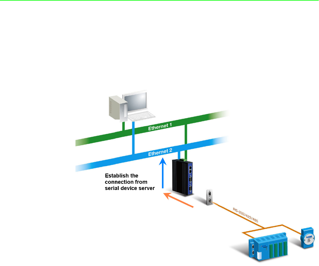
EKI-1521, EKI-1522, and EKI-1524 provide dual Ethernet ports that can establish
two physical Ethernet connections. Dual connection control enables an alternative
backup session that host can connect to device server by the way of second connec-
tion while the primary connection should be lost or dropped.
9 EKI-1351/EKI-1352/EKI-1521/1522/1524 User Manual
Chapter 2 Getting Started
EKI-1351 and EKI-1352 has an 802.11b/g transceiver in addition to its serial and
Ethernet ports. Each serial port is connected to the serial communication port of a
device. The wireless transceiver connects to another wireless device or to an Access
Point (AP).
2.1.2 COM port redirector (Virtual COM port)
Advantech COM port mapping utility is a serial COM port redirector that creates
virtual COM ports and provides access to serial device connected to Advantech
serial device server. Advantech COM port mapping utility is integrated with
Advantech serial device server configuration utility. You can configure the device
server and enable the Virtual COM port using one integrated utility. Advantech serial
device server utility allows you to configure Microsoft applications to communicate
with network enabled device servers as easily as if they were physically installed in or
directly connected on the PC.
The Advantech redirector can create up to 255 virtual COM ports. Application on the
host can open virtual COM port to access the serial device servers at the same time.
The redirector will handle each active virtual COM port as a separate TCP
connection to Advantech serial device servers.
EKI-1351/EKI-1352/EKI-1521/1522/1524 User Manual 10
2.1.2.1 Normal Mode
The Advantech redirector connects the Advantech serial device server while an
application open the COM port and disconnects from the Advantech serial device
server when the application closes the COM port. The redirector uses TCP network
connections to the Advantech serial device server to gain the access to the
connected serial devices.
2.1.2.2 Mutli-Access Mode (Shared COM port mode)
Most of serial devices are connected directly and physically to the PC serial ports via
a cable. The operation system, ex. Windows XP, provides the COM ports that user’s
application can access, and control the serial device through the serial cable. This
means that the serial device can be connected to one host and only one application
on this host can handle input, output and control operation on this device.
If you want to run more than one applications to use a serial device, you can employ
EKI serial device servers that provide a virtual COM pool for a host or multi-hosts on
an Ethernet network. EKI serial device server is located between hosts and serial
devices. Each serial port on the EKI serial device server can allow max. of 5 host
connections through one Ethernet port and two Ethernet ports. There are two major
operation modes for Multi-Access Mode. First one is broadcast mode, EKI serial
device server handles a command from one application and replies the data from the
serial port to all applications that are connecting this serial port. Another one is polling
mode. EKI serial device server handles the command from one application and reply
to this application only. Query from other applications must be queued and wait for
current process completing.
11 EKI-1351/EKI-1352/EKI-1521/1522/1524 User Manual
Chapter 2 Getting Started
By using a serial derive server to share serial device, you eliminate the separate
serial lines and serial devices that can be attached to individual hosts. Collecting the
data from these serial devices become more easily and more effectively.
2.1.3 TCP Server Mode
In TCP server mode, you might initiate the TCP connection from host to EKI serial
device server. This operation mode support max. 5 simultaneous connections for
each serial port on EKI serial device server from one host or several hosts, however
multi-hosts collect the data from one serial port at the same time.
EKI-1351/EKI-1352/EKI-1521/1522/1524 User Manual 12
2.1.4 TCP Client Mode
In TCP Client mode, the TCP connection will be established from EKI serial device
server. This operation mode supports maximum 16 (EKI-1521, EKI-1522, and EKI-
1524) or maximum 4(EKI-1351 and EKI-1352) simultaneous connections for each
serial port on EKI serial device sever to one host or several hosts. You should
configure the IP address and TCP port number of the network hosts which the EKI
serial device connect to using Advantech serial device server utility. After
configuration, when EKI serial device server receives the data from serial port, the
device server will employ the connection to hosts which are configured.
13 EKI-1351/EKI-1352/EKI-1521/1522/1524 User Manual
Chapter 2 Getting Started
2.1.5 Serial Tunneling mode
Two native serial devices can communicate over a Ethernet network without any
intermediate host PC and software programming. Serial Tunneling is very simple to
use. You can use Advantech serial device server utility to designate one serial port
as the tunneling master and another serial device server port as the tunneling slave.
2.1.6 UDP Server/Client Mode
UDP is used primarily for broadcasting messages over a network. In the UDP server
mode, EKI serial device server access max of 8 hosts’ UDP message. In the UDP
client mode, EKI serial device servers transmit UDP message to max of 16 hosts
simultaneously.

EKI-1351/EKI-1352/EKI-1521/1522/1524 User Manual 14
2.1.7 Control Mode
In controlling mode, the EKI serial device server presents a modem interface to the
attached serial device: it accepts AT-style modem commands to connect / disconnect
to other networking device. If you want serial device running application program to
connect/disconnect to different devices by request, you can use controlling mode.
The controlling mode provides three modem AT-style commands. The serial devices
can use these commands to control EKI serial device server connecting or discon-
necting to remote networking device. Thus, intelligent serial devices such as stand-
alone PLC will send /receive data to/from devices one by one via Ethernet.
2.2 Hardware
In this chapter, we will give you a overview of EKI serial device server hardware and
installation.
2.2.1 LED Indicators
2.2.1.1 EKI-1521, EKI-1522 and EKI-1524
There are LEDs display the power status, network status, and serial communication
status located on the front panel of EKI-1521, EKI-1522, and EKI-1524, each of them
has its own specific meaning as below table.
LED Color Status Description
P1 Green ON Power input from first power connector
Off Power off
P2 Green ON Power input from second power con-
nector
Off Power off
Status Yellow Blinking System ON
Off System not work
ON Locate from Utility
LAN(Left side) Yellow ON Link
OFF No Link
Flash Active
LAN(Right side) Green ON 100M
OFF 10M
TX Yellow ON Serial port data being transmitted
OFF Serial port no data being transmitted
RX Green ON Serial port data being received
OFF Serial port no data being received

15 EKI-1351/EKI-1352/EKI-1521/1522/1524 User Manual
Chapter 2 Getting Started
2.2.1.2 EKI-1351 and EKI-1352
These LEDs display the power status, wireless network status, and serial communi-
cation status located on the front panel of EKI-1351, and EKI-1352, each of them has
its own specific meaning as below table.
LED Color Status Description
P1 Green ON Power input from first power connector
Off Power off
P2 Green ON Power input from second power con-
nector
Off Power off
Status Yellow Blinking System ON
Off System not work
ON Locate from Utility
Yellow Off 0% Wireless signal strength
One ON 0~ 35% Wireless signal strength
Two ON 35~70% Wireless signal strength
Three ON Up 100% Wireless signal strength
Fail Yellow Off Wireless module OK
ON Wireless module failure
Link Green Off Disconnect to wireless AP
ON Connect to wireless AP
LAN(Left side) Yellow ON Link
OFF No Link
Flash Active
LAN(Right side) Green ON 100M
OFF 10M
TX Yellow ON Serial port data being transmitted
OFF Serial port no data being transmitted
RX Green ON Serial port data being received
OFF Serial port no data being received
EKI-1351/EKI-1352/EKI-1521/1522/1524 User Manual 16
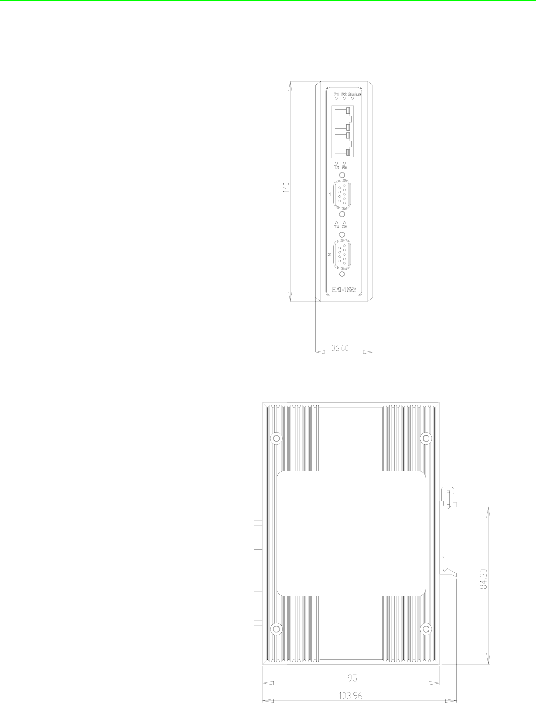
2.2.2 Dimension (units:mm)
2.2.2.1 EKI-1521 and EKI-1522
Figure 2.1 Front View
Figure 2.2 Side View
17 EKI-1351/EKI-1352/EKI-1521/1522/1524 User Manual
Chapter 2 Getting Started
Figure 2.3 Back View
Figure 2.4 Top View
EKI-1351/EKI-1352/EKI-1521/1522/1524 User Manual 18
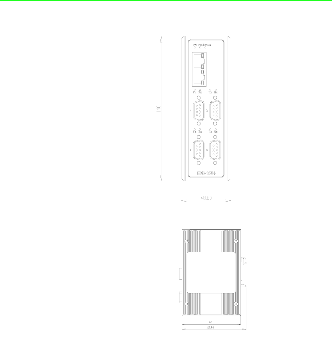
2.2.2.2 EKI-1524
Figure 2.5 Front View
Figure 2.6 Side View

19 EKI-1351/EKI-1352/EKI-1521/1522/1524 User Manual
Chapter 2 Getting Started
Figure 2.7 Back View
Figure 2.8 Top View
EKI-1351/EKI-1352/EKI-1521/1522/1524 User Manual 20
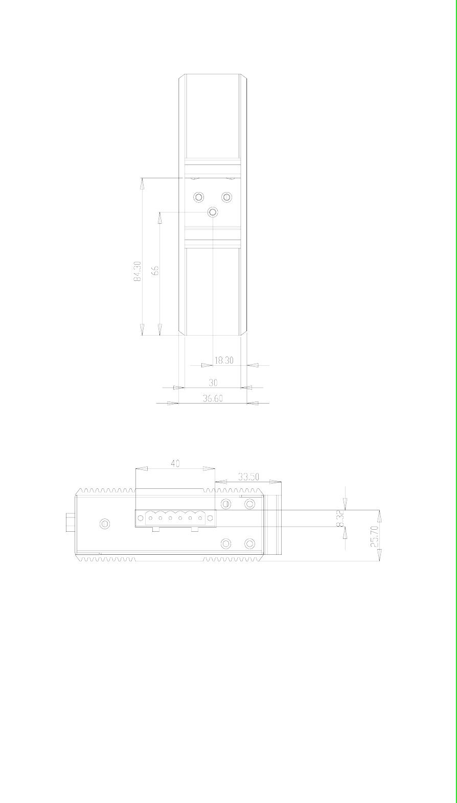
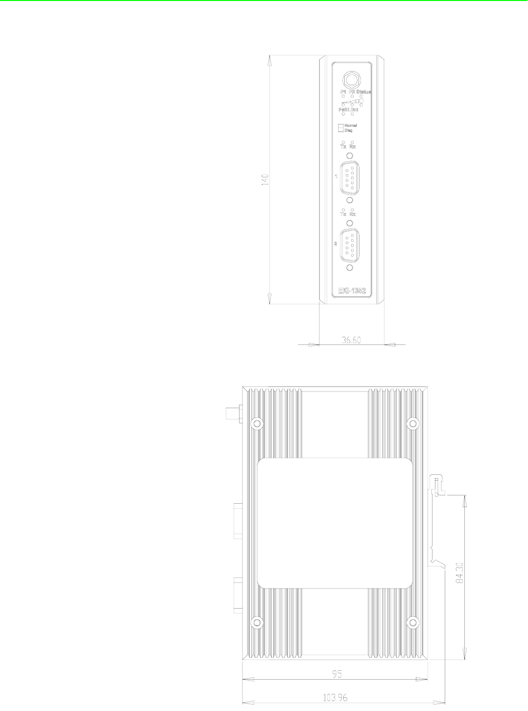
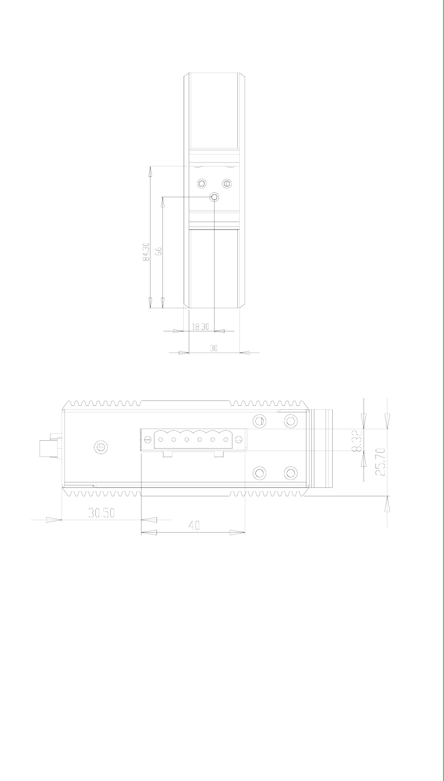
2.2.2.3 EKI-1351 and EKI-1352
Figure 2.9 Front View
Figure 2.10 Side View
21 EKI-1351/EKI-1352/EKI-1521/1522/1524 User Manual
Chapter 2 Getting Started
Figure 2.11 Back View
Figure 2.12 Top View
EKI-1351/EKI-1352/EKI-1521/1522/1524 User Manual 22
2.3 Connecting Hardward
Next, we will explain how to find a proper location for your EKI serial device server,
and then explain how to connect to the network, hook up the power cable, and con-
nect to the EKI device server serial port.
2.3.1 Choosing a Location
Due to its versatility and innovative design, EKI serial device server can be :
Fixed to a panel mount
Fixed to a DIN-rail.
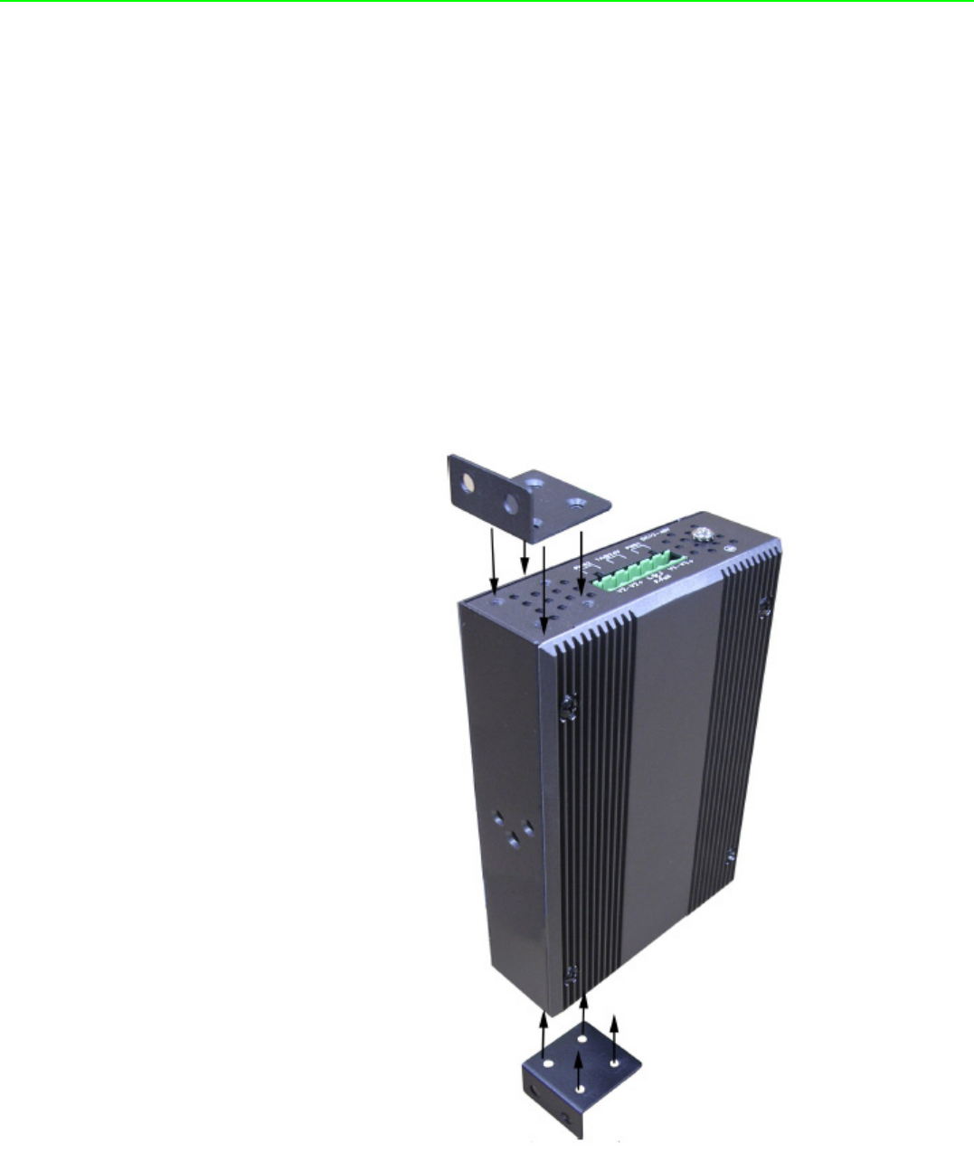
2.3.1.1 Panel/Wallmounting
The EKI serial device servers can be attached to a wall using the included metal
brackets. Each bracket comes with four screws; and then you can install the device
firmly via the components, please see Figure as below.
Figure 2.13 Combining the Metal Mounting Kit
23 EKI-1351/EKI-1352/EKI-1521/1522/1524 User Manual
Chapter 2 Getting Started
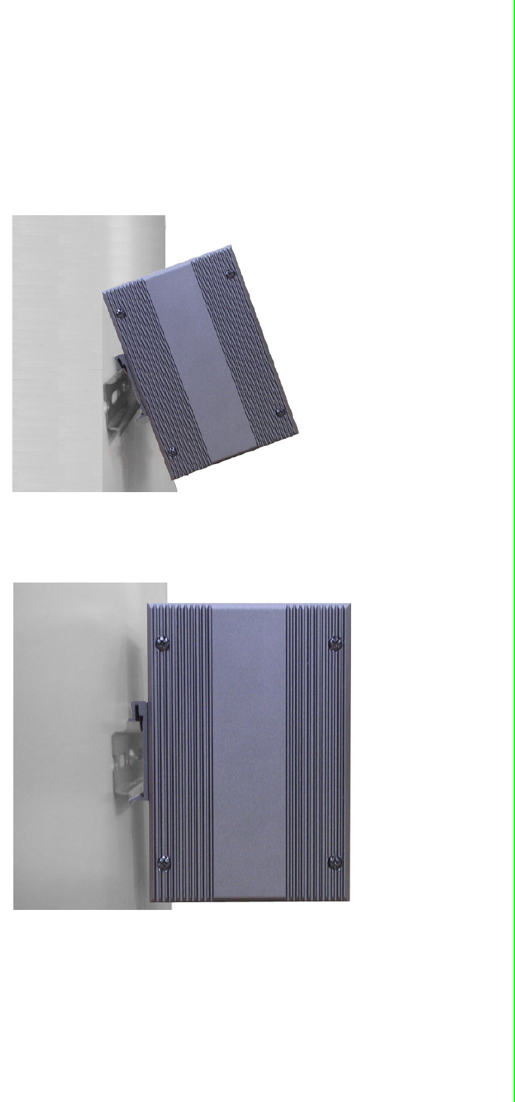
2.3.1.2 DIN-rail Mounting
You can mount the EKI serial device server on a standard DIN rail. The DIN-rail kit is
screwed on the industrial switch when out of factory. If the DIN-rail kit is not screwed
on the industrial switch, please screw the DIN-rail kit on the switch first.
First, hang the EKI serial device sever to the DIN-rail with angle of inclination. See
below figure.
Figure 2.14 DIN-rail Step 1
Then, let the device down straight to slide over the rail smoothly.
Figure 2.15 DIN-rail Step 2
2.3.2 Network Connection
EKI-1521, EKI-1522, and EKI-1524 has 2x RJ-45 that support connection to 10 Mbps
Ethernet, or 100 Mbps Fast Ethernet, and half or full duplex operation. EKI-1521,
EKI-1522 and EKI-1524 can be connected to other hubs or switches through a
twisted-pair straight through the cable or a crossover cable up to 100m long.
EKI-1351/EKI-1352/EKI-1521/1522/1524 User Manual 24
2.3.3 Wireless Connection
EKI-1351 and EKI-1352 operate in the 802.11b/g WLAN environment, which is cre-
ated by an access point working with 802.11b/g protocols. Locate your access point
and connect to the Ethernet network first. Then build up the connection between the
access point and the EKI-1351 and EKI-1352. While the host PC can not connect to
EKI-1351 and EKI-1352, you might switch the EKI-1351 and EKI-1352 as Diag mode.
2.3.3.1 Diag Mode
Set the switch of EKI-1351 and EKI-1352 to Normal Mode, then power on.
Wait for 10 to 20 seconds until the signal quality is stable.
Adjust the switch to Diag Mode, then wait for 5 seconds until the signal link is
blinking.
Return the switch to Normal Mode , then EKI-1351 and EKI-1352 will reboot
automatically with Diag Infrastructure Mode. Now EKI-1351 and EKI-1352 will
automatically search the field site for access points and create a connection to
the one with best signal quality.
Start the Configuration Utility tool on your host (ensure your host PC and the
possible access points that EKI-1351 and EKI-1352 can connect to, are in the
same network). Find the EKI-1351 and EKI-1352 on the network.
Reset the network setting as required. (About Network settings, please refer to
section 3.2.3 of the manual)
After the connection is ready, you can follow the steps shown in chapter 3 to config-
ure and set virtual port mapping through network and access point.
You can check the signal access quality with the wireless signal strength LED indica-
tor. Adjust the antenna of the ADAM module to optimize communication quality.
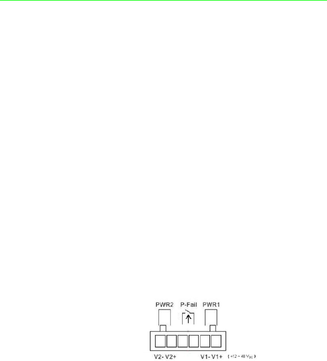
2.3.4 Power Connection
The EKI serial device server supports dual +12 ~ 48 VDC power inputs and power-
fail relay output.
You can connect an alarm indicator, buzzer or other signaling equipment through the
relay output. The relay opens if power input 1 or 2 fails ( “Open” means if you connect
relay output with an LED, the light would be off).