Advantech Co EKI6332GNAE IEEE 802.11 b/g/n Wireless AP/Client/Bridge User Manual V4 12 EA User Manual
Advantech Co Ltd IEEE 802.11 b/g/n Wireless AP/Client/Bridge V4 12 EA User Manual
EKI-6331AN_6332GN_User_Manual

User Manual
EKI-6331AN-BE/
EKI-6332GN-AE
IEEE 802.11n Wi-Fi AP/Client/
Bridge

EKI-6331AN-BE/EKI-6332GN-AE User Manual ii
Copyright
The documentation and the software included with this product are copyrighted 2016
by Advantech Co., Ltd. All rights are reserved. Advantech Co., Ltd. reserves the right
to make improvements in the products described in this manual at any time without
notice. No part of this manual may be reproduced, copied, translated or transmitted
in any form or by any means without the prior written permission of Advantech Co.,
Ltd. Information provided in this manual is intended to be accurate and reliable. How-
ever, Advantech Co., Ltd. assumes no responsibility for its use, nor for any infringe-
ments of the rights of third parties, which may result from its use.
Acknowledgements
Intel and Pentium are trademarks of Intel Corporation.
Microsoft Windows and MS-DOS are registered trademarks of Microsoft Corp.
All other product names or trademarks are properties of their respective owners.
Product Warranty (5 years)
Advantech warrants to you, the original purchaser, that each of its products will be
free from defects in materials and workmanship for five years from the date of pur-
chase.
This warranty does not apply to any products which have been repaired or altered by
persons other than repair personnel authorized by Advantech, or which have been
subject to misuse, abuse, accident or improper installation. Advantech assumes no
liability under the terms of this warranty as a consequence of such events.
Because of Advantech’s high quality-control standards and rigorous testing, most of
our customers never need to use our repair service. If an Advantech product is defec-
tive, it will be repaired or replaced at no charge during the warranty period. For out-
of-warranty repairs, you will be billed according to the cost of replacement materials,
service time and freight. Please consult your dealer for more details.
If you think you have a defective product, follow these steps:
1. Collect all the information about the problem encountered. (For example, CPU
speed, Advantech products used, other hardware and software used, etc.) Note
anything abnormal and list any onscreen messages you get when the problem
occurs.
2. Call your dealer and describe the problem. Please have your manual, product,
and any helpful information readily available.
3. If your product is diagnosed as defective, obtain an RMA (return merchandize
authorization) number from your dealer. This allows us to process your return
more quickly.
4. Carefully pack the defective product, a fully-completed Repair and Replacement
Order Card and a photocopy proof of purchase date (such as your sales receipt)
in a shippable container. A product returned without proof of the purchase date
is not eligible for warranty service.
5. Write the RMA number visibly on the outside of the package and ship it prepaid
to your dealer.
Part No. XXXXXXXXXX Edition 1
Printed in Taiwan January 2016

iii EKI-6331AN-BE/EKI-6332GN-AE User Manual
Declaration of Conformity
CE
This product has passed the CE test for environmental specifications. Test conditions
for passing included the equipment being operated within an industrial enclosure. In
order to protect the product from being damaged by ESD (Electrostatic Discharge)
and EMI leakage, we strongly recommend the use of CE-compliant industrial enclo-
sure products.
FCC Class B
Note: This equipment has been tested and found to comply with the limits for a Class
B digital device, pursuant to part 15 of the FCC Rules. These limits are designed to
provide reasonable protection against harmful interference in a residential installa-
tion. This equipment generates, uses and can radiate radio frequency energy and, if
not installed and used in accordance with the instructions, may cause harmful inter-
ference to radio communications. However, there is no guarantee that interference
will not occur in a particular installation. If this equipment does cause harmful interfer-
ence to radio or television reception, which can be determined by turning the equip-
ment off and on, the user is encouraged to try to correct the interference by one or
more of the following measures:
Reorient or relocate the receiving antenna.
Increase the separation between the equipment and receiver.
Connect the equipment into an outlet on a circuit different from that to which the
receiver is connected.
Consult the dealer or an experienced radio/TV technician for help.
This device complies with Part 15 of the FCC Rules. Operation is subject to the fol-
lowing two conditions:
(1) This device may not cause harmful interference, and
(2) this device must accept any interference received, including interference that may
cause undesired operation.
FCC Radiation Exposure Statement
This equipment complies with FCC radiation exposure limits set forth for an uncon-
trolled environment. To avoid the possibility of exceeding radio frequency exposure
limits, you shall beep a distance of at least 100cm between you and the antenna of
the installed equipment. This transmitter must not be co-located or operating in con-
junction with any other antenna or transmitter.
The availability of some specific channels and/or operational frequency bands are
country dependent and are firmware programmed at the factory to match the
intended destination. The firmware setting is not accessible by the end user.
Caution! Any changes or modifications not expressly approved by the party
responsible for compliance could void the user's authority to operate this
equipment.
EKI-6331AN-BE/EKI-6332GN-AE User Manual iv
Technical Support and Assistance
1. Visit the Advantech web site at www.advantech.com/support where you can find
the latest information about the product.
2. Contact your distributor, sales representative, or Advantech's customer service
center for technical support if you need additional assistance. Please have the
following information ready before you call:
–Product name and serial number
–Description of your peripheral attachments
–Description of your software (operating system, version, application software,
etc.)
–A complete description of the problem
–The exact wording of any error messages
Warnings, Cautions and Notes
Document Feedback
To assist us in making improvements to this manual, we would welcome comments
and constructive criticism. Please send all such - in writing to: support@advan-
tech.com
Warning! Warnings indicate conditions, which if not observed, can cause personal
injury!
Caution! Cautions are included to help you avoid damaging hardware or losing
data. e.g.
There is a danger of a new battery exploding if it is incorrectly installed.
Do not attempt to recharge, force open, or heat the battery. Replace the
battery only with the same or equivalent type recommended by the man-
ufacturer. Discard used batteries according to the manufacturer's
instructions.
Note! Notes provide optional additional information.

vEKI-6331AN-BE/EKI-6332GN-AE User Manual
Safety Instructions
1. Read these safety instructions carefully.
2. Keep this User Manual for later reference.
3. Disconnect this equipment from any AC outlet before cleaning. Use a damp
cloth. Do not use liquid or spray detergents for cleaning.
4. For plug-in equipment, the power outlet socket must be located near the equip-
ment and must be easily accessible.
5. Keep this equipment away from humidity.
6. Put this equipment on a reliable surface during installation. Dropping it or letting
it fall may cause damage.
7. The openings on the enclosure are for air convection. Protect the equipment
from overheating. DO NOT COVER THE OPENINGS.
8. Make sure the voltage of the power source is correct before connecting the
equipment to the power outlet.
9. Position the power cord so that people cannot step on it. Do not place anything
over the power cord.
10. All cautions and warnings on the equipment should be noted.
11. If the equipment is not used for a long time, disconnect it from the power source
to avoid damage by transient overvoltage.
12. Never pour any liquid into an opening. This may cause fire or electrical shock.
13. Never open the equipment. For safety reasons, the equipment should be
opened only by qualified service personnel.
14. If one of the following situations arises, get the equipment checked by service
personnel:
The power cord or plug is damaged.
Liquid has penetrated into the equipment.
The equipment has been exposed to moisture.
The equipment does not work well, or you cannot get it to work according to the
user's manual.
The equipment has been dropped and damaged.
The equipment has obvious signs of breakage.
15. DO NOT LEAVE THIS EQUIPMENT IN AN ENVIRONMENT WHERE THE
STORAGE TEMPERATURE MAY GO BELOW -20° C (-4° F) OR ABOVE 80° C
(140° F). THIS COULD DAMAGE THE EQUIPMENT. THE EQUIPMENT
SHOULD BE IN A CONTROLLED ENVIRONMENT.
16. CAUTION: DANGER OF EXPLOSION IF BATTERY IS INCORRECTLY
REPLACED. REPLACE ONLY WITH THE SAME OR EQUIVALENT TYPE
RECOMMENDED BY THE MANUFACTURER, DISCARD USED BATTERIES
ACCORDING TO THE MANUFACTURER'S INSTRUCTIONS.
17. The sound pressure level at the operator's position according to IEC 704-1:1982
is no more than 70 dB (A).
DISCLAIMER: This set of instructions is given according to IEC 704-1. Advantech
disclaims all responsibility for the accuracy of any statements contained herein.

EKI-6331AN-BE/EKI-6332GN-AE User Manual vi
Safety Precaution - Static Electricity
Follow these simple precautions to protect yourself from harm and the products from
damage.
To avoid electrical shock, always disconnect the power from your PC chassis
before you work on it. Don't touch any components on the CPU card or other
cards while the PC is on.
Disconnect power before making any configuration changes. The sudden rush
of power as you connect a jumper or install a card may damage sensitive elec-
tronic components.

vii EKI-6331AN-BE/EKI-6332GN-AE User Manual
Contents
Chapter 1 Introduction..........................................1
1.1 Introduction ............................................................................................... 2
1.2 Appearance............................................................................................... 2
Figure 1.1 EKI-6332GN-AE/EKI-6331AN-BE .............................. 2
1.3 Key Features............................................................................................. 3
1.4 Typical Application .................................................................................... 3
Figure 1.2 Typical Application...................................................... 3
Chapter 2 Hardware Installation ..........................5
2.1 Preparation before Installation .................................................................. 6
2.1.1 Professional Installation Required ................................................ 6
2.1.2 Safety Precautions........................................................................ 6
2.1.3 Installation Precautions................................................................. 6
2.1.4 Product Package........................................................................... 7
2.2 Hardware Installation ................................................................................ 8
2.2.1 Connect up.................................................................................... 8
2.2.2 Using the Grounding Wire............................................................. 9
2.2.3 Install External Antennas ............................................................ 10
2.2.4 Mount the AP on a Pole.............................................................. 13
2.2.5 Power Up .................................................................................... 14
2.2.6 Connect to the Access Point....................................................... 15
Chapter 3 Basic Settings....................................19
3.1 Factory Default Settings.......................................................................... 20
Table 3.1: EKI-6332GN-AE/EKI-6331AN-BE Factory Default Set-
tings.......................................................................... 20
3.2 System Requirements............................................................................. 20
3.3 How to Login the Web-based Interface................................................... 21
Figure 3.1 Login Page ............................................................... 21
Figure 3.2 Main Page ................................................................ 21
3.4 Basic System Settings ............................................................................ 22
Figure 3.3 Basic System Settings.............................................. 22
3.5 Network Settings ..................................................................................... 22
Figure 3.4 Network Settings ...................................................... 22
Figure 3.5 TCP/IP Settings (Router).......................................... 24
3.6 Time Settings .......................................................................................... 25
Figure 3.6 Time Settings............................................................ 25
3.7 RADIUS Settings..................................................................................... 25
Figure 3.7 RADIUS Settings...................................................... 25
3.8 Basic Wireless Settings........................................................................... 26
Figure 3.8 Basic Wireless Settings............................................ 26
3.9 Site Survey.............................................................................................. 28
Figure 3.9 Site Survey ............................................................... 28
3.10 VAP Profile Settings................................................................................ 29
Figure 3.10VAP Profile Settings ................................................. 29
Figure 3.11VAP Profile Settings ................................................. 29
Chapter 4 Advanced Settings ............................31
4.1 Advanced Wireless Set tings .................................................................. 32

EKI-6331AN-BE/EKI-6332GN-AE User Manual viii
Figure 4.1 Advanced Wireless Settings..................................... 32
4.2 Traffic Shaping........................................................................................ 33
Figure 4.2 Traffic Shaping ......................................................... 33
4.3 Wireless Security Settings ...................................................................... 34
Figure 4.3 Security Settings ...................................................... 34
4.4 Access Control........................................................................................ 36
Figure 4.4 Access Control ......................................................... 36
4.5 WDS Settings.......................................................................................... 37
Figure 4.5 WDS Settings........................................................... 37
Chapter 5 Management...................................... 39
5.1 Password ................................................................................................ 40
Figure 5.1 Password Settings.................................................... 40
5.2 Upgrade Firmware .................................................................................. 40
Figure 5.2 Firmware Upgrade.................................................... 40
5.3 Backup/ Retrieve Settings....................................................................... 41
Figure 5.3 Backup/Retrieve Settings......................................... 41
5.4 Restore Factory Default Settings............................................................ 42
Figure 5.4 Restore to Default Settings ...................................... 42
5.5 Reboot .................................................................................................... 42
Figure 5.5 Reboot...................................................................... 42
5.6 User Certificate ....................................................................................... 43
Figure 5.6 User Certificate......................................................... 43
5.7 Remote Management ............................................................................. 43
Figure 5.7 Remote Management............................................... 43
5.8 SNMP Management................................................................................ 44
Figure 5.8 SNMP Management................................................. 44
Chapter 6 Monitoring Tools............................... 47
6.1 System Log............................................................................................. 48
Figure 6.1 Syslog....................................................................... 48
6.2 Ping Watch Dog...................................................................................... 48
Figure 6.2 Ping Watchdog......................................................... 48
Chapter 7 Status................................................. 51
7.1 View Basic Information ........................................................................... 52
Figure 7.1 Basic Information...................................................... 52
7.2 View Association List .............................................................................. 52
Figure 7.2 Connection ............................................................... 52
Figure 7.3 Association Node Details ......................................... 53
7.3 View Network Flow Statistics.................................................................. 53
Figure 7.4 Network Flow Statistics ............................................ 53
7.4 View ARP Table...................................................................................... 54
Figure 7.5 ARP Table................................................................ 54
7.5 View Bridge Table................................................................................... 54
Figure 7.6 Bridge Table............................................................. 54
7.6 View Routing Table................................................................................. 54
Figure 7.7 Routing Table........................................................... 54
7.7 View Active DHCP Client Table.............................................................. 55
Figure 7.8 DHCP Client Table................................................... 55
Chapter 8 Troubleshooting................................ 57
Figure 8.1 MAC Address ........................................................... 58

ix EKI-6331AN-BE/EKI-6332GN-AE User Manual
Appendix A ASCII...................................................59
A.1 ASCII....................................................................................................... 60
Table A.1: ASCII ........................................................................ 60

EKI-6331AN-BE/EKI-6332GN-AE User Manual x

Chapter 1
1Introduction

EKI-6331AN-BE/EKI-6332GN-AE User Manual 2
1.1 Introduction
EKI-6332GN-AE/EKI-6331AN-BE is a high-performance last-mile broadband solution
that provides reliable wireless network coverage. Designed with IEEE 802.11n stan-
dard, 2x2 MIMO technology and high output power makes it possible deliver up to
300Mbps high data rate with longer range for general purpose application. EKI-
6332GN-AE operates at 2.4GHz band while EKI-6331AN-BE operates at 5GHz
band.
EKI-6332GN-AE/EKI-6331AN-BE can be used as the access point, the client, the
WDS and the AP Repeater. While being as the access point, it can be deployed to
provide wireless networking service. In the other way to be as the client, it can
receive wireless signal over the last mile, helping WISPs deliver internet service to
the new residential and the business customer where wired broadband internet ser-
vice, such as cable and DSL, cannot serve in. In addition, the easy-to-install EKI-
6332GN-AE/EKI-6331AN-BE features with outstanding throughput performance and
a cost-effective design that allows users to have the reliable equipment at the afford-
able price.
1.2 Appearance
Figure 1.1 EKI-6332GN-AE/EKI-6331AN-BE
3EKI-6331AN-BE/EKI-6332GN-AE User Manual
Chapter 1 Introduction
1.3 Key Features
Compliant with IEEE 802.11n standard
Support passive PoE which is supplied with 24V.
High reliable watertight housing endures almost any harsh environments
Support 64/128/152-bit WEP and 802.1X, WPA, WPA2, WPA&WPA2,WPA-
PSK, WPA2-PSK, and WPA-PSK&WPA2-PSK etc
User-friendly Web and SNMP-based management interface
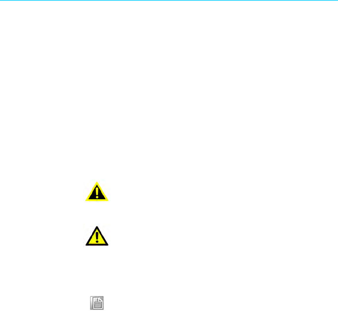
1.4 Typical Application
EKI-6332GN-AE/EKI-6331AN-BE can be applied into the following environments:
Cost-effectively provide long distance backhaul for remote areas (e.g. village, oil
well, island, mountain and etc.)
Establish local backhaul for campus, farm and factory
Provide and access for video streaming or surveillance for industrial and mining
enterprises
Figure 1.2 Typical Application

EKI-6331AN-BE/EKI-6332GN-AE User Manual 4

Chapter 2
2Hardware Installation

EKI-6331AN-BE/EKI-6332GN-AE User Manual 6
This chapter describes safety precautions and product information you have to know
and check before installing EKI-6332GN-AE/EKI-6331AN-BE.
2.1 Preparation before Installation
2.1.1 Professional Installation Required
Please seek assistance from a professional installer who is well trained in the RF
installation and knowledgeable in the local regulations.
2.1.2 Safety Precautions
1. To keep you safe and install the hardware properly, please read and follow these
safety precautions.
2. If you are installing EKI-6332GN-AE/EKI-6331AN-BE for the first time, for your
safety as well as others’, please seek assistance from a professional installer
who has received safety training on the hazards involved.
3. Keep safety as well as performance in mind when selecting your installation
site, especially where there are electric power and phone lines.
4. When installing EKI-6332GN-AE/EKI-6331AN-BE, please note the following
things:
Do not use a metal ladder;
Do not work on a wet or windy day;
Wear shoes with rubber soles and heels, rubber gloves, long sleeved shirt or
jacket.
5. When the system is operational, avoid standing directly in front of it. Strong RF
fields are present when the transmitter is on.
2.1.3 Installation Precautions
To keep EKI-6332GN-AE/EKI-6331AN-BE well while you are installing it, please read
and follow these installation precautions.
1. Users MUST use a proper and well-installed grounding and surge arrestor with
EKI-6332GN-AE/EKI-6331AN-BE; otherwise, a random lightening could easily
cause fatal damage to EKI-6332GN-AE/EKI-6331AN-BE. EMD (Lightning)
DAMAGE IS NOT COVERED UNDER WARRNTY.
2. Users MUST use the “Power cord & PoE Injector” shipped in the box with EKI-
6332GN-AE/EKI-6331AN-BE. Use of other options will likely cause damage to
EKI-6332GN-AE/EKI-6331AN-BE.

7EKI-6331AN-BE/EKI-6332GN-AE User Manual
Chapter 2 Hardware Installation
2.1.4 Product Package
The product package you have received should contain the following items. If any of
them are not included or damaged, please contact your local vendor for support.
EKI-6332GN-AE/EKI-6331AN-BE × 1
Detachable 5dBi Antennas × 2
Pole Mounting Ring × 2
24VDC Power Cord & PoE Injector × 1
Ferrite Suppression Core × 1
Grounding Wire × 1
Product CD × 1
Note! Product CD contains Quick Installation Guide and User Manual.
Pole Mounting Ring
Round Cable Suppression Core
24VDC Power Cord & PoE Injector
Warning! Users MUST use the “Power cord & PoE Injector” shipped in the box
with EKI-6332GN-AE/EKI-6331AN-BE. Use of other options will likely
cause damage to EKI-6332GN-AE/EKI-6331AN-BE.
EKI-6331AN-BE/EKI-6332GN-AE User Manual 8
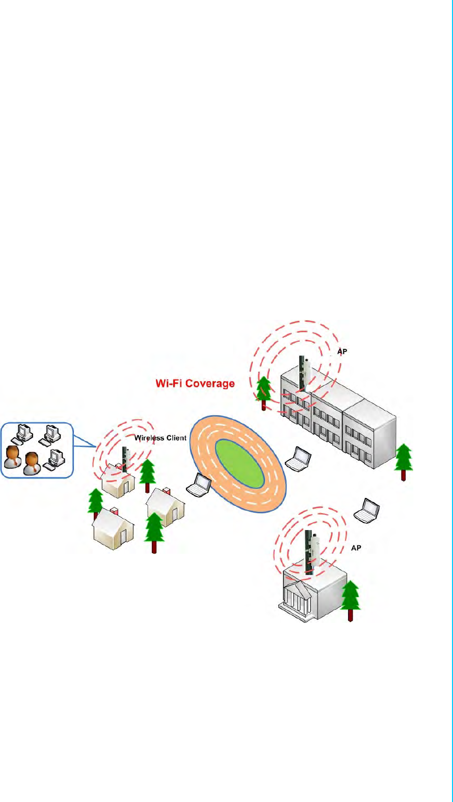
2.2 Hardware Installation
2.2.1 Connect up
1. The bottom of the Access Point is a movable cover. Grab the cover and pull it
back harder to take it out as the figure shown below.
2. Plug a standard Ethernet cable into the RJ45 port.
9EKI-6331AN-BE/EKI-6332GN-AE User Manual
Chapter 2 Hardware Installation
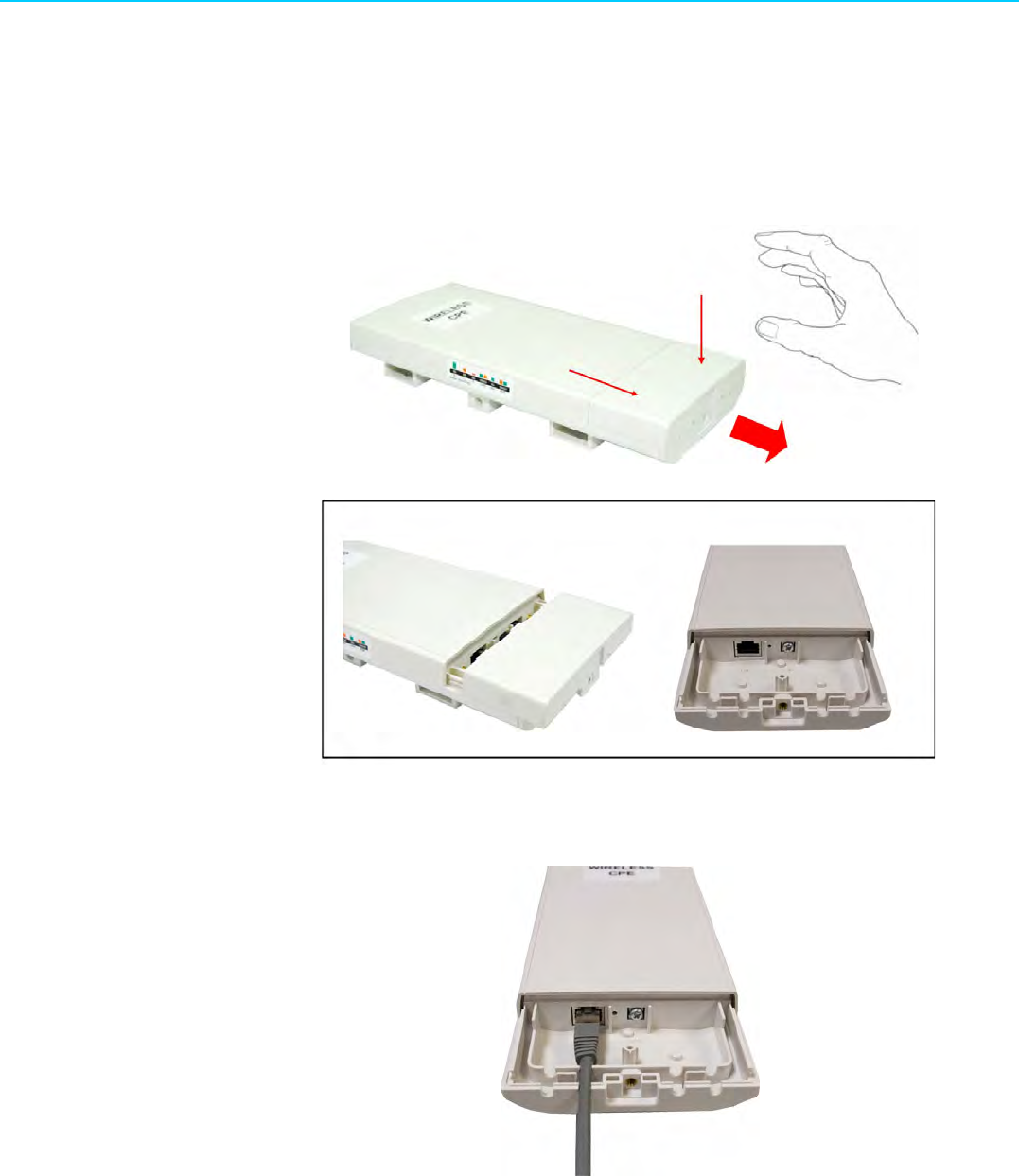
3. Slide the cover back and press down the lock button to seal the bottom of the
Access Point.
2.2.2 Using the Grounding Wire
EKI-6332GN-AE/EKI-6331AN-BE is equipped with a grounding wire. It is important
that the Access Point, cables, and PoE Injector must be properly connected to earth
ground during normal use against surges or ESD.
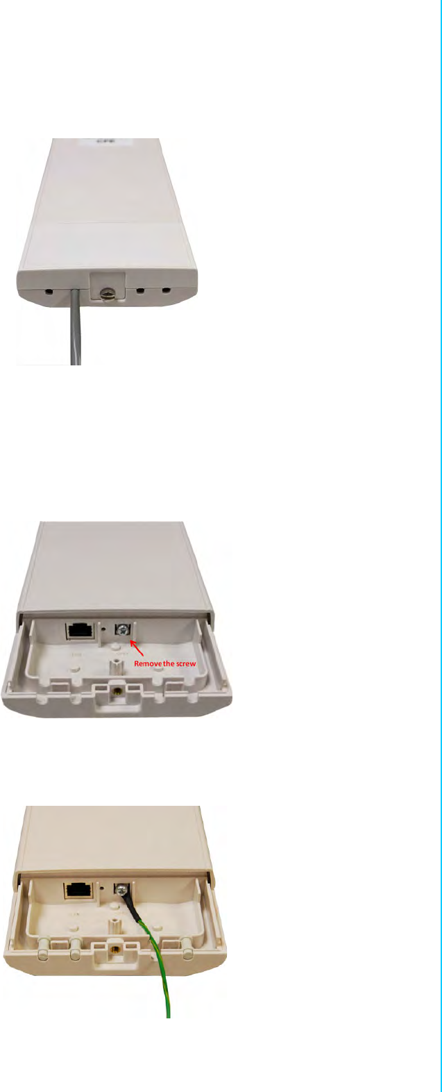
1. Remove the screw on the grounding point at the bottom of the Access Point.
2. Put the grounding wire on the grounding point at the bottom of the Access Point.
Then screw the grounding wire to tighten up.
EKI-6331AN-BE/EKI-6332GN-AE User Manual 10
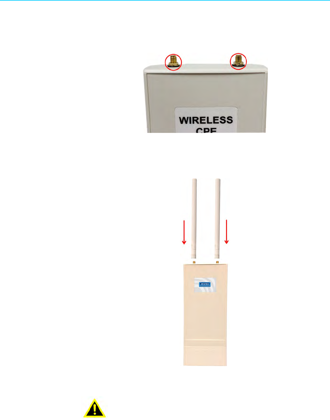
2.2.3 Install External Antennas
The Access Point provides two reverse SMA antenna connectors for connecting
external antennas.
1. Connect external antennas that came with the package to the SMA-type con-
nectors on top of the Access Point. For longer coverage distance, it is recom-
mended that higher gain antennas be used to best suit the application.
Warning! Users MUST power off the Access Point first before connecting the
external antenna to it. Do not power on the device for a certain of time
without physically attaching the external antenna; otherwise, damage
might be caused to the unit itself.
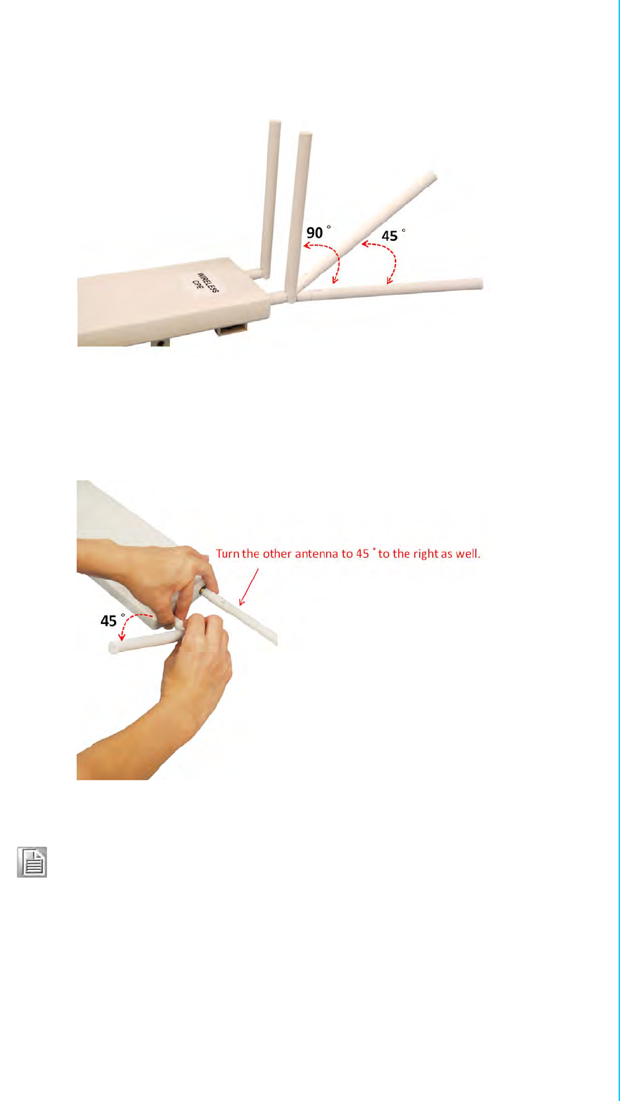
11 EKI-6331AN-BE/EKI-6332GN-AE User Manual
Chapter 2 Hardware Installation
2. Bend the antennas to 90 degree or 45 degree.
3. You may turn one antenna 45 degrees to the left and the other 45 degrees to the
right. The tilted antennas are a reasonable way to operate and the best way if
the antennas are fairly close together since they couple together much less than
if they are both pointed in the same direction (parallel).
Note! The polarization of antennas should be properly aligned. Maximum sig-
nal strength between bridges occurs when both bridges are using identi-
cal polarization.
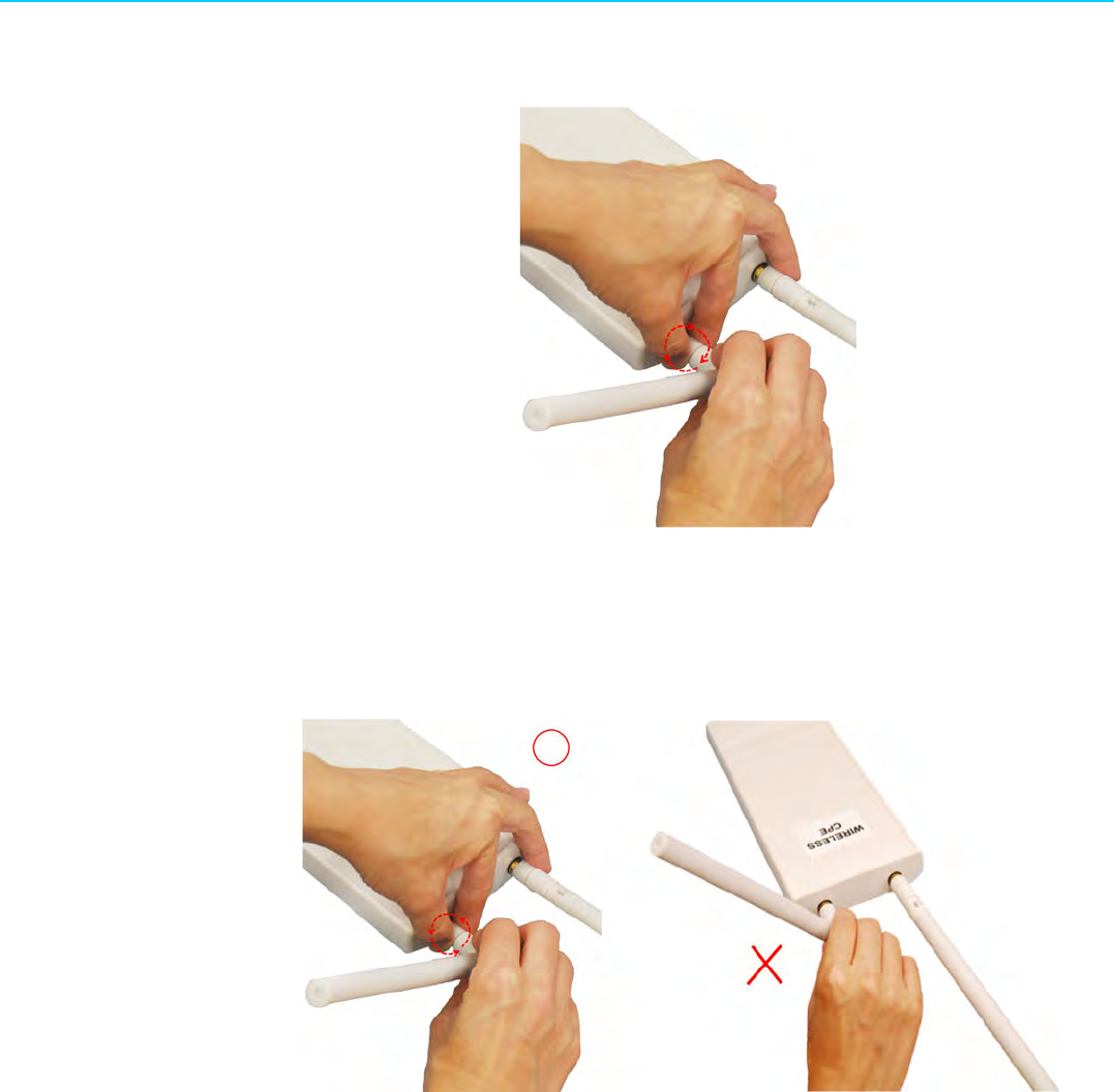
EKI-6331AN-BE/EKI-6332GN-AE User Manual 12
4. Tighten up the connector joint clockwise to fix the antennas.
5. To adjust antennas, loose the connector joint counterclockwise first, then adjust
antenna to the desired position. DO NOT bend or turn the antennas without
loosening the connector joint, otherwise, damage might be caused to the anten-
nas.
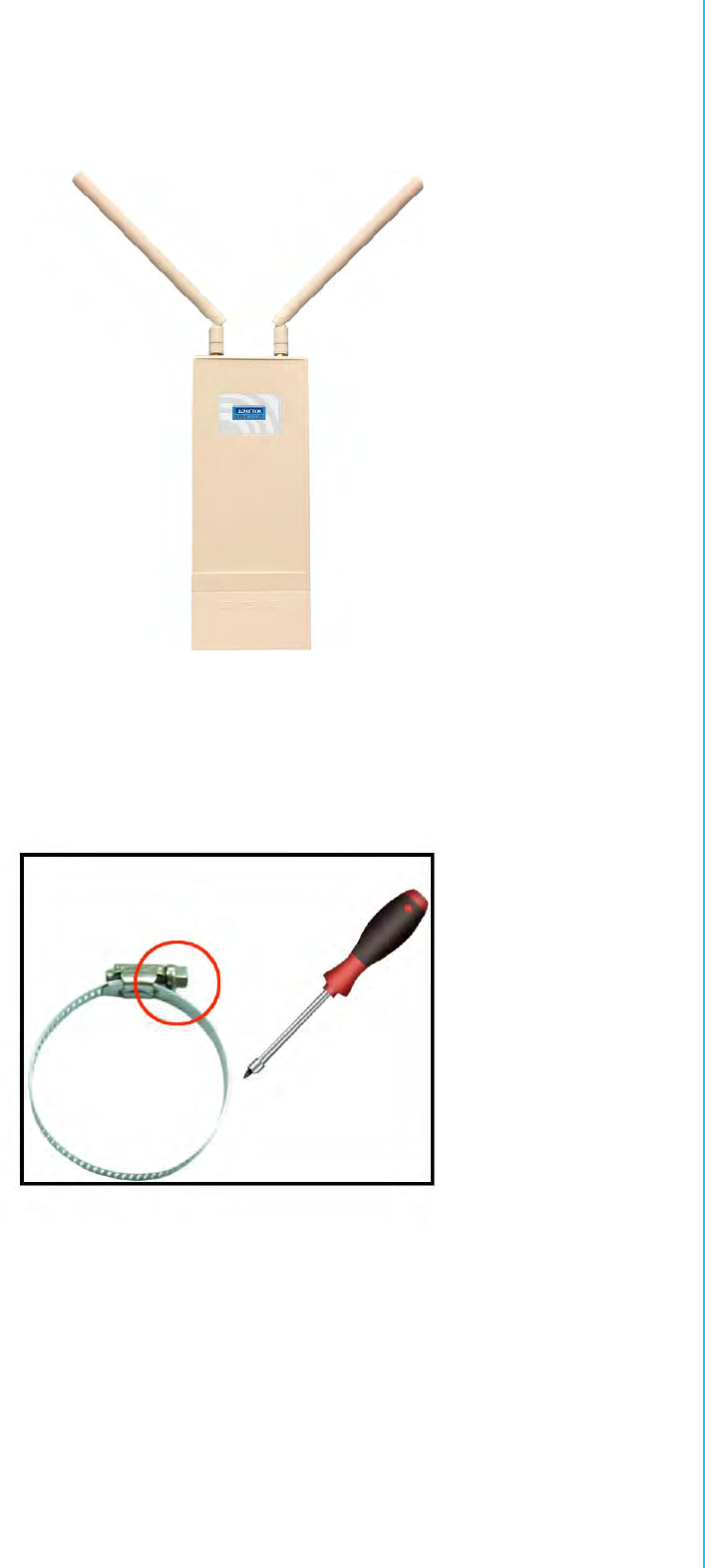
13 EKI-6331AN-BE/EKI-6332GN-AE User Manual
Chapter 2 Hardware Installation
6. Antenna installation is complete.
2.2.4 Mount the AP on a Pole
1. Turn the Access Point over. Put the pole mounting ring through the middle hole
of it. Note that you should unlock the pole mounting ring with a screw driver
before putting it through the device as the following right picture shows.
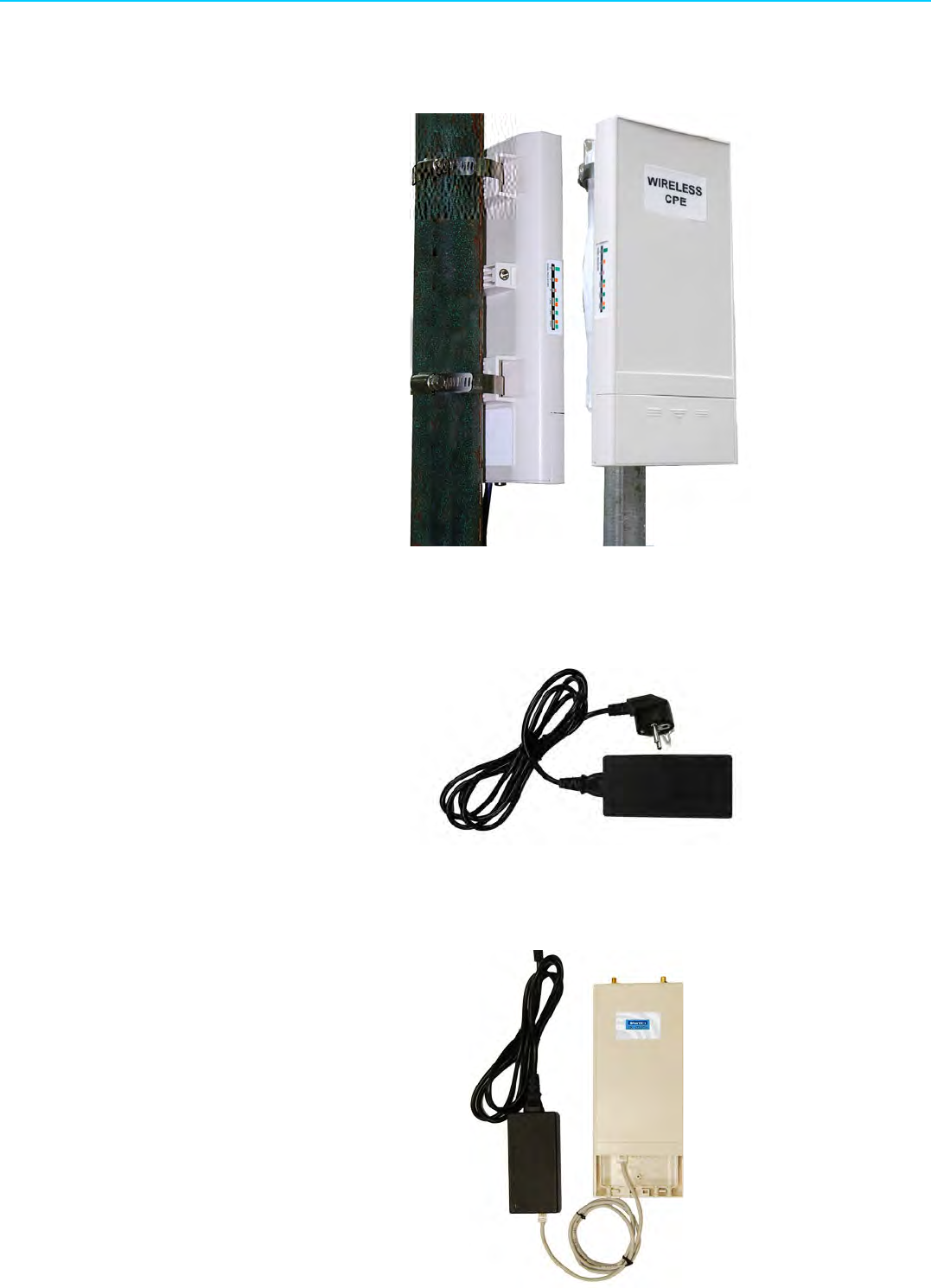
EKI-6331AN-BE/EKI-6332GN-AE User Manual 14
2. Mount the Access Point steadily to the pole by locking the pole mounting ring
tightly.
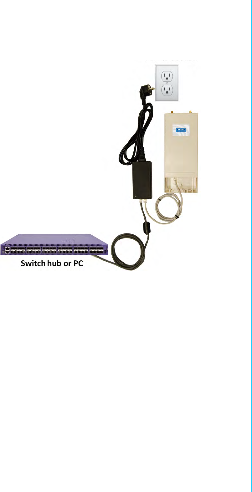
2.2.5 Power Up
1. Connect power cord to the PoE injector as the following right picture shows.
2. Connect the Ethernet cable that connects the Access Point to the “POE” port of
the PoE injector as figured below.

15 EKI-6331AN-BE/EKI-6332GN-AE User Manual
Chapter 2 Hardware Installation
3. Connect the power plug to a power socket. The Access Point will be powered
up immediately.
2.2.6 Connect to the Access Point
To be able to configure and manage the Access Point, please do the followings:
1. Open the ferrite core by unsnapping the connector latches. The core will open,
revealing a concave surface.
2. Lay the Ethernet cable into the core, usually within 2 to 3 inches of the connec-
tor. You may have to experiment with the final location depending on the effec-
tiveness of the high frequency abatement.
3. Loop the cable around and through the core. This helps "lock" the core in place,
and may be required in circumstances with severe interference.

EKI-6331AN-BE/EKI-6332GN-AE User Manual 16
4. Close the core and snap the halves back together.
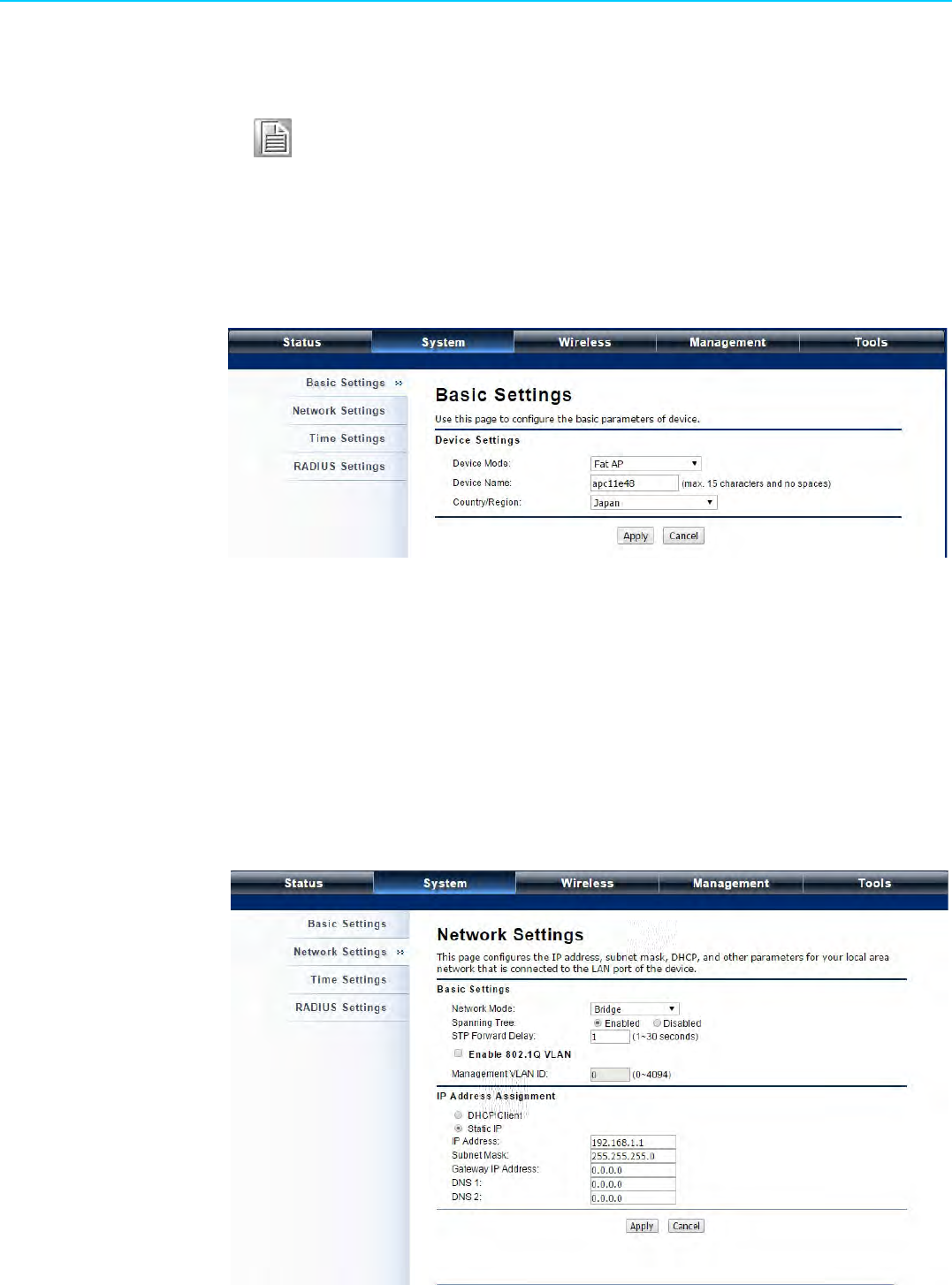
5. Connect the Ethernet cable with suppression core to the “Data In” port of the
PoE injector.
17 EKI-6331AN-BE/EKI-6332GN-AE User Manual
Chapter 2 Hardware Installation
6. Connect the other end of Ethernet cable to a PC or a switch hub. The hardware
installation is complete.
To configure the Access Point, please refer to Chapter 3 Basic Settings.

EKI-6331AN-BE/EKI-6332GN-AE User Manual 18

Chapter 3
3Basic Settings

EKI-6331AN-BE/EKI-6332GN-AE User Manual 20
3.1 Factory Default Settings
We’ll elaborate EKI-6332GN-AE/EKI-6331AN-BE factory default settings. You can re-
acquire these parameters by default. If necessary, please refer to the “Restore Fac-
tory Default Settings”.
3.2 System Requirements
Before configuration, please make sure your system meets the following require-
ments:
A computer coupled with 10/ 100 Base-TX adapter;
Configure the computer with a static IP address of 192.168.1.x, as the default IP
address of EKI-6332GN-AE/EKI-6331AN-BE is 192.168.1.1. (X cannot be 0, 1,
nor 255);
A Web browser on PC for configuration such as Microsoft Internet Explorer 6.0
or above, Netscape, Firefox or Google Chrome.
Table 3.1: EKI-6332GN-AE/EKI-6331AN-BE Factory Default Settings
Features Factory Default Settings
Username admin
Password password
Wireless Device Name apXXXXXX (X represents the last 6 digits of Ethernet
MAC address)
Operating Mode AP
Data Rate Auto
LAN IP Address 192.168.1.1
Subnet Mask 255.255.255.0
Gateway 0.0.0.0
Primary DNS Server 0.0.0.0
Secondary DNS Server 0.0.0.0
Spanning Tree Enable
Data Rate Auto
Output Power Full
WMM Enabled
RTS Threshold (byte) 2346
Fragmentation Length (byte) 2346
Channel Protection None
Short GI Enable
Distance 1000m
Flow Control by AP Disable
Security Open System
Encryption None

21 EKI-6331AN-BE/EKI-6332GN-AE User Manual
Chapter 3 Basic Settings
3.3 How to Login the Web-based Interface
EKI-6332GN-AE/EKI-6331AN-BE provides you with user-friendly Web-based man-
agement tool.
Open Web browser and enter the IP address (Default: 192.168.1.1) of EKI-
6332GN-AE/EKI-6331AN-BE into the address field. You will see the login page
as below.
Figure 3.1 Login Page
Enter the username (Default: admin) and password (Default: password) respec-
tively and click “Login” to login the main page of EKI-6332GN-AE/EKI-6331AN-
BE. As you can see, this management interface provides five main options in
the black bar above, which are Status, System, Wireless, Management and
Tools.
Figure 3.2 Main Page
EKI-6331AN-BE/EKI-6332GN-AE User Manual 22
3.4 Basic System Settings
For users who use EKI-6332GN-AE/EKI-6331AN-BE for the first time, it is recom-
mended that you begin configuration from “Basic Settings” in “System” shown below:
Figure 3.3 Basic System Settings
Device Name: Specify the device name, which is composed of no more than 15
characters with (0-9), (A-Z), (a-z) or (-).
Country Region: The availability of some specific channels and/or operational
frequency bands is country dependent.
3.5 Network Settings
The Network Settings allows you to change network, IP address and configure few
network parameters like spanning tree and management VLAN ID. Make configura-
tion in “Network Settings” from “System”.
Figure 3.4 Network Settings
Note! The username and password are case-sensitive, and the password
should be no more than 19 characters!

23 EKI-6331AN-BE/EKI-6332GN-AE User Manual
Chapter 3 Basic Settings
Network Mode:
Specify the network mode, including Bridge and Router. It is easy to configure
parameters in Bridge Mode; however, users must pay extra attention to the way
they configure the device when it is set to Router Mode. For details, please refer
to TCP/IP Settings”.
Spanning Tree:
Spanning Tree Protocol (STP) is a link management protocol for AP which pro-
vides path redundancy while preventing loops in a network. STP allows only
one active path at a time between the Access Points but establish the redundant
link as a backup if the initial link fails.
STP Forward Delay:
STP Forward Delay is the time spent in detecting and learning network tree
topology state before entering the forward state. Default time value is 1 sec.
802.1Q VLAN:
To allow users on the VLAN to access the WEB page of EKI-6332GN-AE/EKI-
6331AN-BE, you need to enable “Enable 802.1Q VLAN” and assign a manage-
ment VLAN ID for your device. Make sure the assigned management VLAN ID
is identical to your network VLAN ID to avoid failures of accessing the Web page
of EKI-6332GN-AE/EKI-6331AN-BE.
IP Address Assignment:
Users may change the settings for IP Address, Subnet Mask, and DHCP
Server.
Obtain IP Address Automatically:
If a DHCP server exists in your network, you can check this option, thus EKI-
6332GN-AE/EKI-6331AN-BE is able to obtain IP settings automatically from
that DHCP server.
Use Fixed IP Address:
Check this option. You have to specify a static IP address, subnet mask, default
gateway and DNS server for the Access Point manually. Make sure the speci-
fied IP address is unique on your network in order to prevent IP conflict.
If EKI-6332GN-AE/EKI-6331AN-BE configured as Router mode, you need to
configure some additional TCP/IP parameters for accessing the Internet.
Note!
When the IP address of the Access Point is changed, the clients on
the network often need to wait for a while or even reboot before
they can access the new IP address. For an immediate access to
the bridge, please flush the netbios cache on the client computer
by running the “nbtstat –r” command before using the device name
of the Access Point to access its Web Management page.
In case EKI-6332GN-AE/EKI-6331AN-BE is unable to obtain an IP
address from a valid DHCP server, it will fall back to default static
IP address.
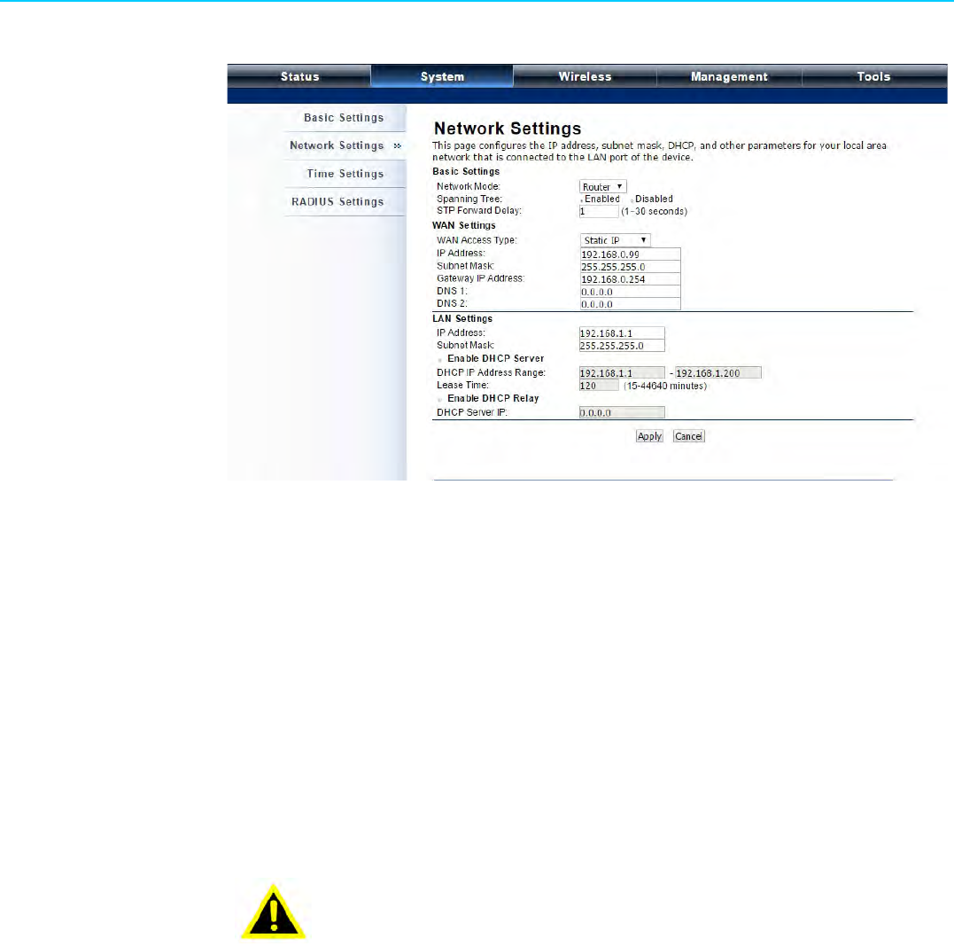
EKI-6331AN-BE/EKI-6332GN-AE User Manual 24
Figure 3.5 TCP/IP Settings (Router)
WAN Access Type:
Specify the Internet access method to Static IP, DHCP or PPPOE. Users must
enter WAN IP Address, Subnet Mask, Gateway settings provided by your ISPs.
LAN Settings:
When DHCP Server is disabled, users can specify IP address and subnet mask
for the Access Point manually. Make sure the specified IP address is unique on
your network in order to prevent IP conflict. When DHCP Server is enabled,
users may specify DHCP IP Address Range, DHCP Subnet Mask, DHCP Gate-
way and Lease Time (15-44640 minutes). A DHCP relay agents is used to for-
ward DHCP requests and replies between clients and servers when they are not
on the same physical subnet. To enable the DHCP relay agent, check the
“Enable DHCP Relay” checkbox and enter the IP address of the DHCP server.
Warning!
In AP mode, EKI-6332GN-AE/EKI-6331AN-BE must establish con-
nection with another wireless device before it is set to Router
mode. To access the unit in Router mode via wired port, please
type the WAN IP address to enter the web page for WAN is on
wired port and LAN is on wireless port. Or, you can access device
through the wireless device connected with the Access Point.
In wireless client mode, users can access the Access Point via its
wired port, for WAN is on wireless port and LAN is on wired port
when device is set to Router mode.
Bridge mode and AP Repeater mode are similar to AP mode when
device is set to Router mode; WAN is on wired port and LAN is on
wireless port. Thus users must also connect the Access Point with
another wireless device before it is set to Router mode and access
the Access Point via the connected wireless device.
25 EKI-6331AN-BE/EKI-6332GN-AE User Manual
Chapter 3 Basic Settings
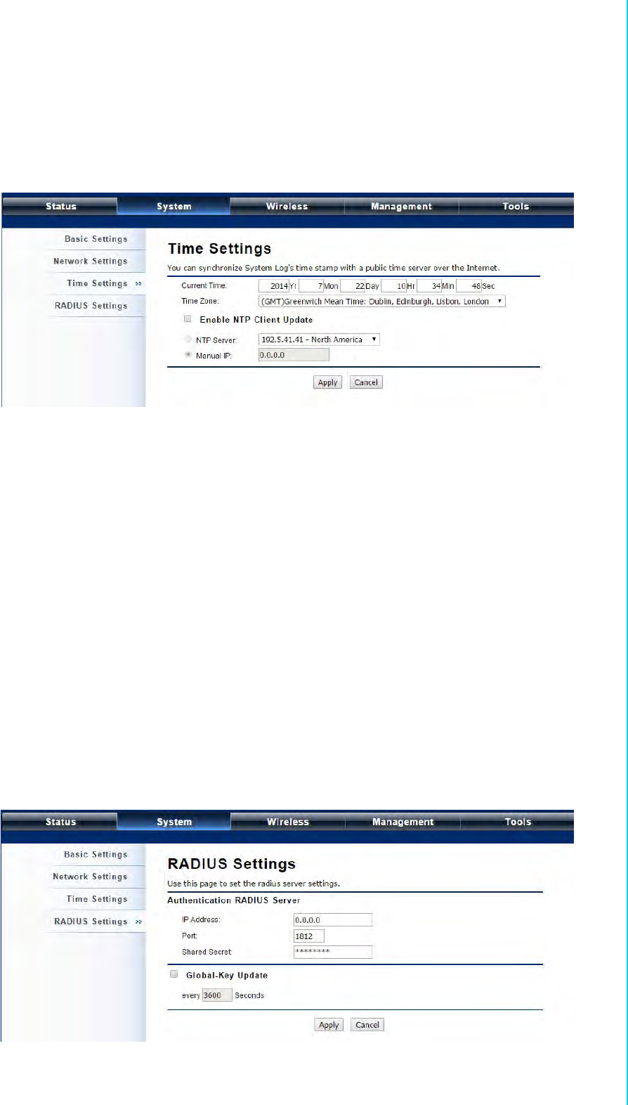
3.6 Time Settings
Compliant with NTP, EKI-6332GN-AE/EKI-6331AN-BE is capable of keeping its time
in complete accord with the Internet time. Make configuration in “Time Settings” from
“System”. To use this feature, check “Enable NTP Client Update” in advance.
Figure 3.6 Time Settings
Current Time:
Display the present time in Yr, Mon, Day, Hr, Min and Sec.
Time Zone Select:
Select the time zone from the dropdown list.
NTP Server:
Select the time server from the “NTP Server” dropdown list.
Manual IP:
Manually input the IP address of available time server. Hit “Apply” to save set-
tings.
3.7 RADIUS Settings
RADIUS (Remote Authentication Dial-In User Service) is a server for remote user
authentication and accounting; playing a central role in the network in providing the
capabilities of authenticating, authorizing, accounting, auditing, alarming and etc. It
allows an organization to maintain user profiles in a central database that all remote
servers can share.
Open “RADIUS Settings” in “System” to make RADIUS configuration.
Figure 3.7 RADIUS Settings
EKI-6331AN-BE/EKI-6332GN-AE User Manual 26
Authentication RADIUS Server
This is for RADIUS authentication. It can communicate with RADIUS through IP
Address, Port and Shared Secret.
–IP Address: Enter the IP address of the Radius Server;
–Port: Enter the port number of the Radius Server;
–Shared Secret: This secret, which is composed of no more than 31 charac-
ters, is shared by EKI-6332GN-AE/EKI-6331AN-BE and RADIUS during
authentication.
Global-Key Update:
Check this option and specify the time interval between two global-key updates.
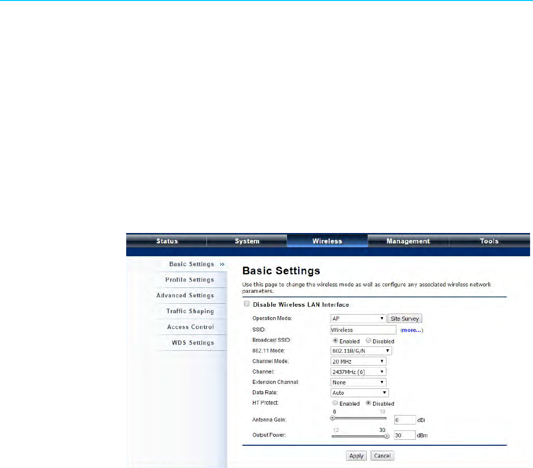
3.8 Basic Wireless Settings
Open “Basic Settings” in “Wireless” as below to make basic wireless configuration.
Figure 3.8 Basic Wireless Settings
Disable Wireless LAN Interface:
Check this option to disable WLAN interface, then the wireless module of EKI-
6332GN-AE/EKI-6331AN-BE will stop working and no wireless device can con-
nect to it.
Operation Mode:
Four operating modes are available in EKI-6332GN-AE/EKI-6331AN-BE.
–AP: EKI-6332GN-AE/EKI-6331AN-BE establishes a wireless coverage and
receives connectivity from other wireless devices.
–Wireless Client: EKI-6332GN-AE/EKI-6331AN-BE is able to connect to the
AP and thus join the wireless network around it.
–Bridge: EKI-6332GN-AE/EKI-6331AN-BE establishes wireless connectivity
with other APs by keying in remote MAC address. Please refer to the “WDS
Setting” for detailed configuration.
–AP Repeater: EKI-6332GN-AE/EKI-6331AN-BE servers as AP and Bridge
concurrently. In other words, EKI-6332GN-AE/EKI-6331AN-BE can provide
connectivity services for ACCESS POINTs under Bridge mode.
Wireless Network Name (SSID):
This wireless network name is shared among all associated devices in your

27 EKI-6331AN-BE/EKI-6332GN-AE User Manual
Chapter 3 Basic Settings
wireless network. Keep it identical on all those devices. Note that the SSID is
case-sensitive and cannot exceed 32 characters.
Broadcast SSID:
Under AP mode, hiding network name is necessary when you are in a wireless
environment that may have potential risk. By disabling broadcast SSID, the STA
can not scan and find EKI-6332GN-AE/EKI-6331AN-BE, so that malicious
attack by some illegal STA could be avoided.
802.11 Mode:
EKI-6332GN-AE can communicate with wireless devices of 802.11b/g or
802.11b/g/n. For EKI-6331AN-BE, which is 802.11a/n
Channel Mode:
Four levels are available: 5MHz, 10MHz, 20MHz and 40MHz. The last one can
enhance data throughput, but it takes more bandwidth, thus it might cause
potential interference
Channel:
Channel varies much as the available band differs from country to country.
Select a proper operating channel in the drop-down list according to your situa-
tion.
Extension Channel:
Only applicable to AP, AP Repeater, and 40MHz channel width) indicates the
use of channel bonding that allows EKI-6332GN-AE/EKI-6331AN-BE to use two
channels at once. Two options are available: Upper Channel and Lower Chan-
nel.
Data Rate:
Usually “Auto” is preferred. Under this rate, EKI-6332GN-AE/EKI-6331AN-BE
will automatically select the highest available rate to transmit. In some cases,
however, like where there is no great demand for speed, you can have a rela-
tively-low transmit rate for compromise of a long distance.
HT Protect:
Enable HT (High Throughput) protect to ensure HT transmission with MAC
mechanism. Under 802.11n mode, wireless client can be divided into HT STA
and Non-HT STA, among which the one with HT protect enabled gets higher
throughput.
Antenna Gain:
Allows you specify the gain of the external antenna. The antenna gain calcu-
lates the TX power back off needed to remain in compliance with regulations.
Output Power (per chain):
Specify the signal transmission power. The higher the output power is, the wider
the signal can cover, but the power consumption will be greater accordingly.
Enable MAC Clone:
Available only under wireless client mode, it hides the MAC address of the AP
while displays the one of the device connected to the Access Point. Default is
Auto MAC Clone. User may choose to enter the MAC address to be cloned
manually.
EKI-6331AN-BE/EKI-6332GN-AE User Manual 28
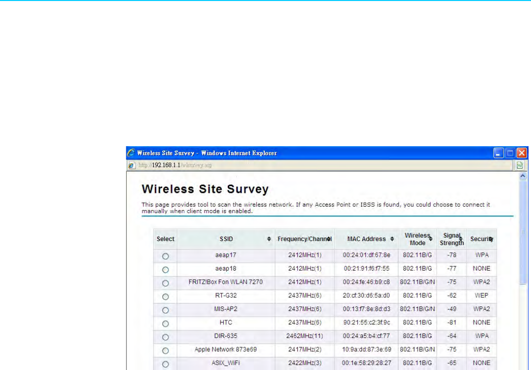
3.9 Site Survey
Under wireless client mode, EKI-6332GN-AE/EKI-6331AN-BE is able to perform site
survey, through which, information on the available Access Points will be detected.
Open “Basic Settings” in “Wireless”, by clicking the “Site Survey” button beside “Wire-
less Mode” option, the wireless site survey window will pop up with a list of available
AP in the vicinity. Select the AP you would like to connect and click “Selected” to
establish connection.
Figure 3.9 Site Survey
29 EKI-6331AN-BE/EKI-6332GN-AE User Manual
Chapter 3 Basic Settings
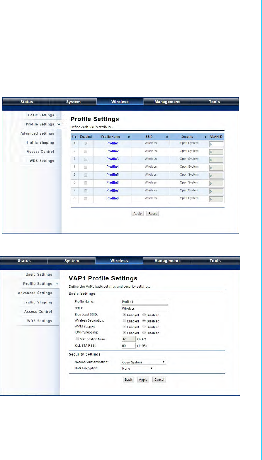
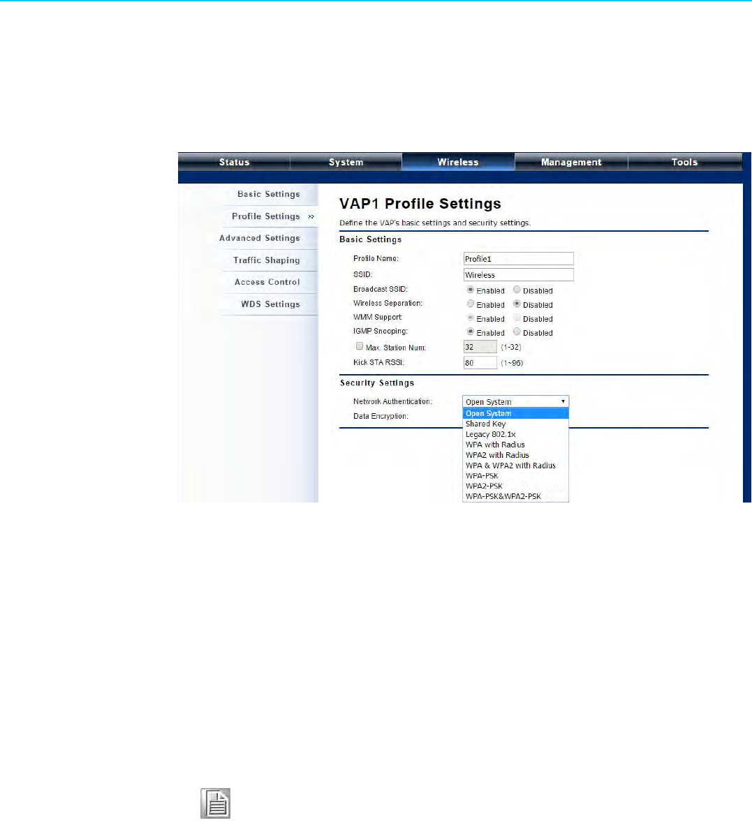
3.10 VAP Profile Settings
Available in AP mode, EKI-6332GN-AE/EKI-6331AN-BE allows up to 8 virtual SSIDs
on a single BSSID and to configure different profile settings such as security and
VLAN ID to each SSID. To create a virtual AP, you may check the Enabled box of the
profile and click on the profile (eg. Profile 2) to configure wireless and security set-
tings. Hit Apply to active the profile.
Figure 3.10 VAP Profile Settings
Figure 3.11 VAP Profile Settings
Profile Name:
Name of the VAP profile
SSID:
Assign a network name for the VAP
Broadcast SSID:
In AP mode, hiding network name is necessary when you are in a wireless envi-

EKI-6331AN-BE/EKI-6332GN-AE User Manual 30
ronment that may have potential risk. By disabling broadcast SSID, the STA
cannot scan and find EKI-6332GN-AE/EKI-6331AN-BE, so that malicious attack
by some illegal STA could be avoided.
Wireless Separation:
Wireless separation is an ideal way to enhance the security of network transmis-
sion. Under the mode except wireless client mode, enable “Wireless Separa-
tion” can prevent the communication among associated wireless clients.
WMM Support:
WMM (Wi-Fi Multimedia) is a subset of 802.11e. It allows wireless communica-
tion to define a priority limit on the basis of data type under AP mode only, thus
those time-sensitive data, like video/audio data, may own a higher priority than
common one. To enable WMM, the wireless client should also support it
Max. Station Number:
By checking the “Max. Station Num” the Access Point will only allow up to 32
wireless clients to associate with for better bandwidth for each client. By dis-
abling the checkbox the Access Point will allow up to 128 clients to connect, but
it is likely to cause network congestion or poor performance.
IGMP Snooping:
Available in AP/Router mode, IGMP snooping is the process of listening to
IGMP network traffic. By enabling IGMP snooping, the AP will listen to IGMP
membership reports, queries and leave messages to identify the ports that are
members of multicast groups. Multicast traffic will only be forwarded to ports
identified as members of the specific multicast group or groups.
Security Setting:|
To prevent unauthorized radios from accessing data transmitting over the con-
nectivity, EKI-6332GN-AE/EKI-6331AN-BE provides you with rock solid security
settings. For detailed information please go to Chapter 4 Wireless Security Set-
ting.

Chapter 4
4Advanced Settings
EKI-6331AN-BE/EKI-6332GN-AE User Manual 32
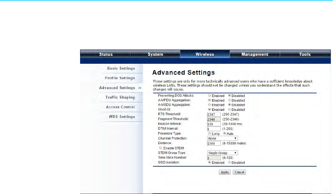
4.1 Advanced Wireless Set tings
Open “Advanced Settings” in “Wireless” to make advanced wireless settings.
Figure 4.1 Advanced Wireless Settings
MPDU/A-MSDU Aggregation:
The data rate of your AP except wireless client mode could be enhanced greatly
with this option enabled; however, if your wireless clients don’t support A-
MPDU/A-MSDU aggregation, it is not recommended to enable it.
Short GI:
Under 802.11n mode, enable it to obtain better data rate if there is no negative
compatibility issue.
RTS Threshold:
EKI-6332GN-AE/EKI-6331AN-BE sends RTS (Request to Send) frames to cer-
tain receiving station and negotiates the sending of a data frame. After receiving
an RTS, that STA responds with a CTS (Clear to Send) frame to acknowledge
the right to start transmission. The setting range is 0 to 2346 in byte. Setting it
too low may result in poor network performance. Leave it at its default of 2346 is
recommended.
Fragmentation Length:
Specify the maximum size in byte for a packet before data is fragmented into
multiple packets. Setting it too low may result in poor network performance.
Leave it at its default of 2346 is recommended.
Beacon Interval:
Specify the frequency interval to broadcast packets. Enter a value between 20
and 1024.
DTIM Interval:
DTIM, which stands for Delivery Traffic Indication Message, is contained in the
data packets. It is for enhancing the wireless transmission efficiency. The default
is set to 1. Enter a value between 1 and 255.
Preamble Type:
It defines some details on the 802.11 physical layer. “Long” and “Auto” are
available.
Distance
To decrease the chances of data retransmission at long distance, EKI-6332GN-

33 EKI-6331AN-BE/EKI-6332GN-AE User Manual
Chapter 4 Advanced Settings
AE/EKI-6331AN-BE can automatically adjust proper ACK timeout value by
specifying distance of the two nodes.
4.2 Traffic Shaping
It allows the administrator to manage the traffic flow to ensure optimal performance.
Figure 4.2 Traffic Shaping
Enable Traffic Shaping:
Check this box to control the overall bandwidth for a specific VAP network.
Interface Selection:
Select the VAP network you would like to enable traffic shaping.
Outgoing Traffic Rate:
To specify maximum outgoing bandwidth to a certain rate in kbit/s.
Outgoing Traffic Burst:
To specify the buffer size for outgoing traffic that can be sent within a given unit
of time. The suggested value is 20KBytes. You may just leave the default value
there, and then the connection will be bound to the traffic shaping rule at all
times. You may decrease it to smaller value if the incoming traffic limit is smaller.
EKI-6331AN-BE/EKI-6332GN-AE User Manual 34
4.3 Wireless Security Settings
To prevent unauthorized radios from accessing data transmitting over the connectiv-
ity, EKI-6332GN-AE/EKI-6331AN-BE provides you with rock solid security settings.
Open “Profile Setting” in “Wireless” and enter “VAP Profile 1 Settings” as below.
Figure 4.3 Security Settings
Network Authentication
–Open System: It allows any device to join the network without performing
any security check.
–Shared Key: Data encryption and key are required for wireless authentica-
tion (Not available in Bridge/AP Repeater mode).
–Legacy 802.1x: Available in AP/Wireless Client mode, it provides the rights
to access the wireless network and wired Ethernet. With User and PC iden-
tity, centralized authentication as well as dynamic key management, it con-
trols the security risk of wireless network to the lowest. To serve the 802.1x,
at least one EAP type should be supported by the RADIUS Server, AP and
wireless client.
–WPA with RADIUS: Available in AP/Wireless Client mode, with warrant
(username, password and etc.) offered by user, this kind of authentication
can be realized with specific RADIUS server. This is the common way to be
adopted in large enterprise network.
–WPA2 with RADIUS: Available in AP/Wireless Client mode, as a new ver-
sion of WPA, only all the clients support WPA2, can it be available. If it is
selected, AES encryption and RADIUS server is required. It is only available
in AP/Wireless Client mode.
Note! For first time users, if EAP type “TLS” is selected, you need to import
valid user certificate given by CA in prior. To import user certificates,
please refer to Chapter 5 Management/Certificate Settings for more
details.

35 EKI-6331AN-BE/EKI-6332GN-AE User Manual
Chapter 4 Advanced Settings
–WPA&WPA2 with RADIUS: Available in AP mode, it provides options of
WPA (TKIP) or WPA2 (AES) for the client. If it is selected, the data encryption
type must be TKIP + AES and the RADIUS server must be set.
–WPA-PSK: It is a simplified WPA mode with no need for specific authentica-
tion server. In this so-called WPA Pre-Shared Key, all you have to do is just
pre-enter a key in each WLAN node and this is the common way to be
adopted in large and middle enterprise as well as residential network.
–WPA2-PSK: As a new version of WPA, only all the clients support WPA2, can
it be available. If it is selected, the data encryption can only be AES and the
passphrase is required.
–WPA-PSK&WPA2-PSK: Available in AP mode, it provides options of WPA
(TKIP) or WPA2 (AES) encryption for the client. If it is selected, the data
encryption can only be TKIP + AES and the passphrase is required.
Data Encryption
If data encryption is enabled, the key is required and only sharing the same key
with other wireless devices can the communication be established.
–None: Available only when the authentication type is open system.
–64 bits WEP: It is made up of 10 hexadecimal numbers.
–128 bits WEP: It is made up of 26 hexadecimal numbers.
–152 bits WEP: It is made up of 32 hexadecimal numbers.
–TKIP: Temporal Key Integrity Protocol, which is a kind of dynamic encryption,
is co-used with WPA-PSK, etc.
–AES: Advanced Encryption Standard, it is usually co-used with WPA2-PSK,
WPA, WPA2, etc.
–TKIP + AES: It allows for backwards compatibility with devices using TKIP.
Note! We strongly recommend you enable wireless security on your network!
Only setting the same Authentication, Data Encryption and Key in EKI-
6332GN-AE/EKI-6331AN-BE and other associated wireless devices,
can the communication be established!
EKI-6331AN-BE/EKI-6332GN-AE User Manual 36
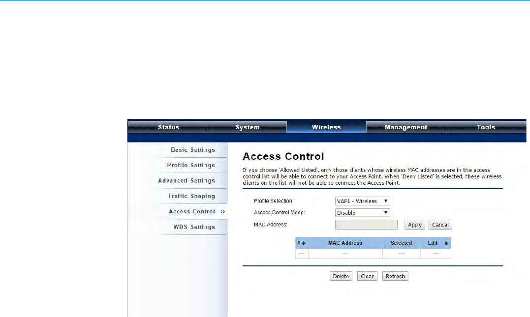
4.4 Access Control
The Access Control appoints the authority to wireless client on accessing EKI-
6332GN-AE/EKI-6331AN-BE, thus a further security mechanism is provided. This
function is available only under AP mode.
Open “Access Control” in “Wireless” as below.
Figure 4.4 Access Control
Profile Selection
Select the VAP profile you would like to enable Access Control
Access Control Mode
If you select “Allow Listed”, only those clients whose wireless MAC addresses
are in the access control list will be able to connect to your AP. While when
“Deny Listed” is selected, those wireless clients on the list will not be able to
connect the AP.
MAC Address
Enter the MAC address of the wireless client that you would like to list into the
access control list, click “Apply” then it will be added into the table at the bottom.
Delete/Clear
Check the box before one or more MAC addresses of wireless client(s) that you
would like to cancel, and click “Delete” or “Clear” to cancel that access control
rule.

37 EKI-6331AN-BE/EKI-6332GN-AE User Manual
Chapter 4 Advanced Settings
4.5 WDS Settings
Bridge mode extends the range of your network without having to use cables to link
the Access Points by using the Wireless Distribution System (WDS): Simply put, you
can link the Access Points wirelessly. To enable Bridge mode, please go to Wireless
> Basic Settings and choose “Bridge” in Operation Mode. Then go to “WDS Settings”
in “Wireless” as below:
Figure 4.5 WDS Settings
Enter the MAC address of another AP you wirelessly want to connect to into the
appropriate field and click “Apply” to save settings.
Note!
WDS Settings is available only under Bridge and AP Repeater
Mode.
Bridge uses the WDS protocol that is not defined as the standard
thus compatibility issues between equipment from different ven-
dors may arise. Moreover, Tree or Star shape network topology
should be used in all WDS use-cases (i.e. if AP2 and AP3 are
specified as the WDS peers of AP1, AP2 should not be specified
as the WDS peer of AP3 and AP3 should not be specified as the
WDS peer of AP2 in any case). Mesh and Ring network topologies
are not supported by WDS and should be avoided in all the use
cases.

EKI-6331AN-BE/EKI-6332GN-AE User Manual 38

Chapter 5
5Management
EKI-6331AN-BE/EKI-6332GN-AE User Manual 40
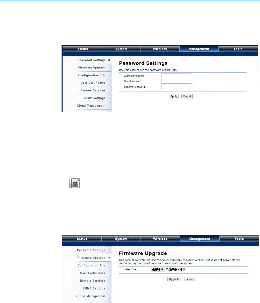
5.1 Password
From “Password Settings” in “Management”, you can change the password to man-
age your IEEE 802.11n VAC Access Point.
Figure 5.1 Password Settings
Current Password:
Enter the current password.
New Password:
Enter the new password.
Confirm Password:
Enter the new password again for confirmation.
5.2 Upgrade Firmware
Open “Firmware Upload” in “Management” and follow the steps below to upgrade
firmware locally or remotely through IEEE 802.11n VAC Access Point’s Web:
Figure 5.2 Firmware Upgrade
Click “Browse” to select the firmware file you would like to load;
Click “Upload” to start the upload process;
Wait a few minutes, the VAC Access Point will reboot after successful upgrade.
Note! The password is case-sensitive and its length cannot exceed 19 charac-
ters!
41 EKI-6331AN-BE/EKI-6332GN-AE User Manual
Chapter 5 Management
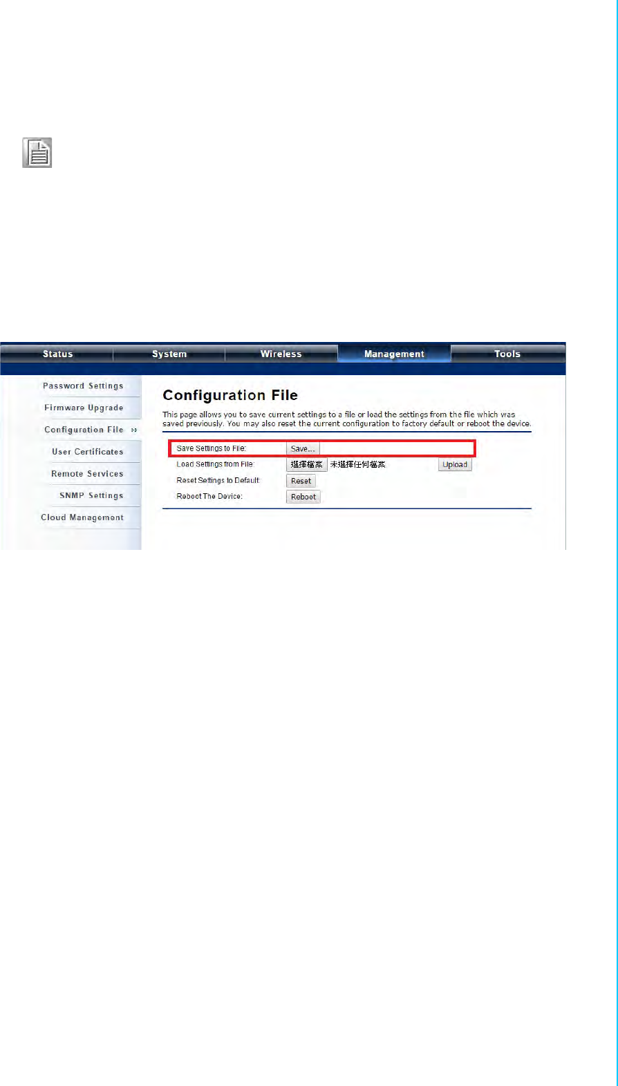
5.3 Backup/ Retrieve Settings
It is strongly recommended you back up configuration information in case of some-
thing unexpected. If tragedy hits your device, you may have an access to restore the
important files by the backup. All these can be done by the local or remote computer.
Open “Configuration File” in “Management” as below:
Figure 5.3 Backup/Retrieve Settings
Save Setting to File:
By clicking “Save”, a dialog box will pop up. Save it, then the configuration file
ap.cfg will be generated and saved to your local computer.
Load Settings from File:
By clicking “Browse”, a file selection menu will appear, select the file you want to
load, like ap.cfg; Click “Upload” to load the file. After automatically rebooting,
new settings are applied.
Note! Do NOT cut the power off during upgrade, otherwise the system may
crash!
EKI-6331AN-BE/EKI-6332GN-AE User Manual 42
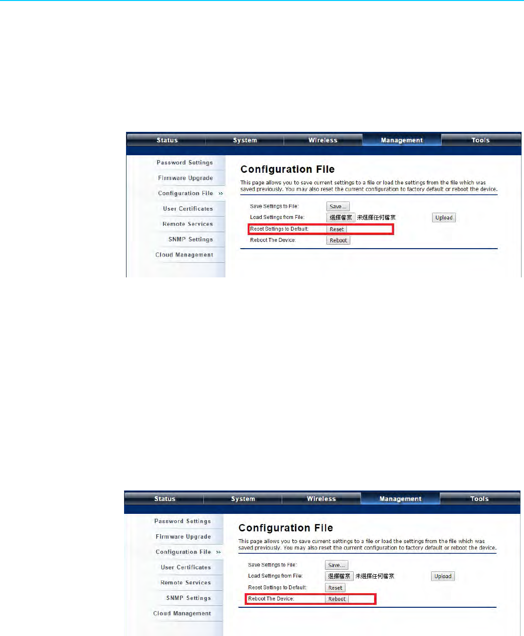
5.4 Restore Factory Default Settings
The IEEE 802.11n VAC Access Point provides two ways to restore the factory default
settings:
Restore factory default settings via Web
From “Configuration File”, clicking “Reset” will eliminate all current settings and
reboot your device, then default settings are applied.
Figure 5.4 Restore to Default Settings
Restore factory default settings via Reset Button
If software in IEEE 802.11n VAC Access Point is unexpectedly crashed and no
longer reset the unit via Web, you may do hardware reset via the reset button.
Press and hold the button for at least 5 seconds and then release it until the
PWR LED gives a blink.
5.5 Reboot
You can reboot your IEEE 802.11n VAC Access Point from “Configuration File” in
“Management” as below:
Click “Reboot” and hit “Yes” upon the appeared prompt to start reboot process. This
takes a few minutes.
Figure 5.5 Reboot
43 EKI-6331AN-BE/EKI-6332GN-AE User Manual
Chapter 5 Management
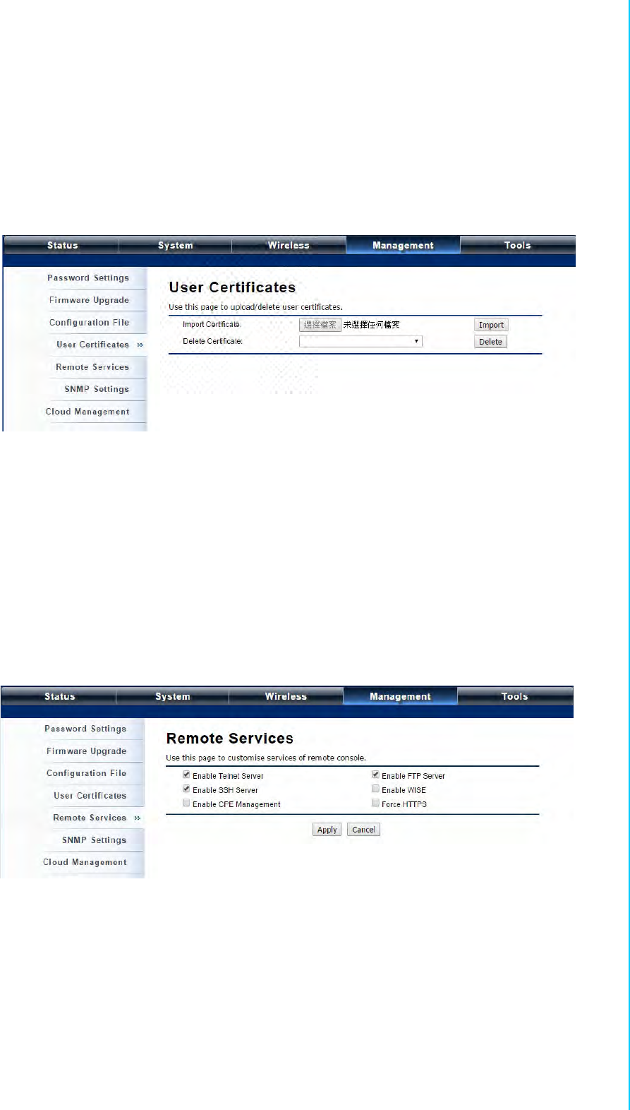
5.6 User Certificate
Under Wireless Client mode, when EAP-TLS is used, the RADIUS server must know
which user certificates to trust. The Server can trust all certificates issued by a given
CA.
To import a user certificate, from Import User Certificates, click “Browse” and specify
the location where the user certificate is placed. Click “Import”.
Figure 5.6 User Certificate
Delete User Certificate:
Delete the selected user certificate.
Import User Certificates:
Imported the user certificate
5.7 Remote Management
The IEEE 802.11n VAC Access Point provides a variety of remotes managements
including Telnet, SNMP, FTP, SSH, HTTPS and exclusive WISE tool, making configu-
ration more convenient and secure.
Figure 5.7 Remote Management
EKI-6331AN-BE/EKI-6332GN-AE User Manual 44
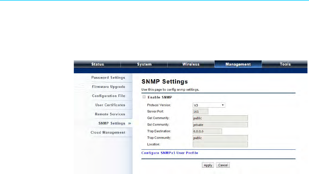
5.8 SNMP Management
The IEEE 802.11n VAC Access Point supports SNMP for convenient remote man-
agement. Open “SNMP Settings” in “Management” shown below. Set the SNMP
parameters and obtain MIB file before remote management.
Figure 5.8 SNMP Management
Protocol Version:
Select the SNMP version, and keep it identical on the IEEE 802.11n VAC
Access Point and the SNMP manager. The IEEE 802.11n VAC Access Point
supports SNMP v2/v3.
Server Port:
Change the server port for a service if needed; however you have to use the
same port to use that service for remote management.
Get Community:
Specify the password for the incoming Get and GetNext requests from the man-
agement station. By default, it is set to public and allows all requests.
Set Community:
Specify the password for the incoming Set requests from the management sta-
tion. By default, it is set to private.
Trap Destination:
Specify the IP address of the station to send the SNMP traps to.
Trap Community:
Specify the password sent with each trap to the manager. By default, it is set to
public and allows all requests.
Configure SNMPv3 User Profile
For SNMP protocol version 3, you can click “Configure SNMPv3 User Profile” in
blue to set the details of SNMPv3 user. Check “Enable SNMPv3 Admin/User” in
advance and make further configuration.
–User Name: Specify a user name for the SNMPv3 administrator or user. Only
the SNMP commands carrying this user name are allowed to access the
IEEE 802.11n VAC Access Point.
–Password: Specify a password for the SNMPv3 administrator or user. Only
the SNMP commands carrying this password are allowed to access the IEEE
802.11n Wireless VAC Access Point.
–Confirm Password: Input that password again to make sure it is your
desired one.

45 EKI-6331AN-BE/EKI-6332GN-AE User Manual
Chapter 5 Management
–Access Type: Select “Read Only” or “Read and Write” accordingly.
–Authentication Protocol: Select an authentication algorithm. SHA authenti-
cation is stronger than MD5 but is slower.
–Privacy Protocol: Specify the encryption method for SNMP communication.
None and DES are available. None means no encryption is applied. DES is
a Data Encryption Standard that applies a 58-bit key to each 64-bit block of
data.

EKI-6331AN-BE/EKI-6332GN-AE User Manual 46

Chapter 6
6Monitoring Tools
EKI-6331AN-BE/EKI-6332GN-AE User Manual 48
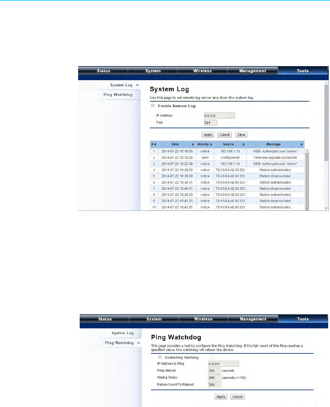
6.1 System Log
System log is used for recording events occurred on the IEEE 802.11n VAC Access
Point, including station connection, disconnection, system reboot and etc.
Open “System Log” in “Tools” as below.
Figure 6.1 Syslog
Remote Syslog Server:
Enable System log to alert remote server.
–IP Address: Specify the IP address of the remote server.
–Port: Specify the port number of the remote server.
6.2 Ping Watch Dog
If you mess your connection up and cut off your ability the log in to the unit, the ping
watchdog has a chance to reboot due to loss of connectivity.
Figure 6.2 Ping Watchdog
Enable Ping Watchdog:
To activate ping watchdog, check this checkbox.
IP Address to Ping:
Specify the IP address of the remote unit to ping.

49 EKI-6331AN-BE/EKI-6332GN-AE User Manual
Chapter 6 Monitoring Tools
Ping Interval:
Specify the interval time to ping the remote unit.
Startup Delay:
Specify the startup delay time to prevent reboot before the IEEE 802.11n VAC
Access Point is fully initialized.
Failure Count To Reboot:
If the ping timeout packets reached the value, the IEEE 802.11n VAC Access
Point will reboot automatically.

EKI-6331AN-BE/EKI-6332GN-AE User Manual 50

Chapter 7
7Status
EKI-6331AN-BE/EKI-6332GN-AE User Manual 52
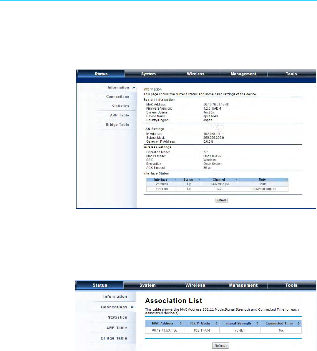
7.1 View Basic Information
Open "Information" in "Status" to check the basic information of the Access Point,
which is read only. Information includes system information, LAN settings, wireless
setting and interface status. Click "Refresh" at the bottom to have the real-time infor-
mation.
Figure 7.1 Basic Information
7.2 View Association List
Open "Connections" in "Status" to check the information of associated wireless
devices such as MAC address, signal strength, connection time, IP address, etc. All
is read only. Click "Refresh" at the bottom to update the current association list.
Figure 7.2 Connection
53 EKI-6331AN-BE/EKI-6332GN-AE User Manual
Chapter 7 Status
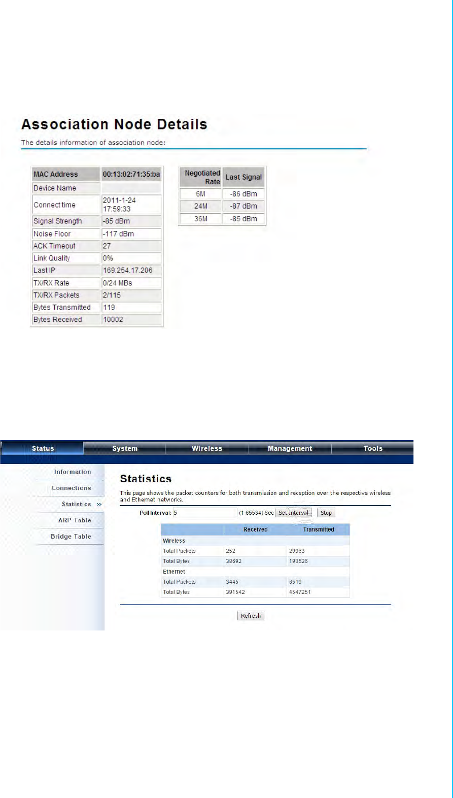
By clicking on the MAC address of the selected device on the web you may see more
details including device name, connection time, signal strength, noise floor, ACK
timeout, link quality, IP information, current data rate, current TX/RX packets.
Figure 7.3 Association Node Details
7.3 View Network Flow Statistics
Open "Statistics" in "Status" to check the data packets received on and transmitted
from the wireless and Ethernet ports. Click "Refresh" to view current statistics.
Figure 7.4 Network Flow Statistics
Poll Interval
Specify the refresh time interval in the box beside "Poll Interval" and click "Set
Interval" to save settings. "Stop" helps to stop the auto refresh of network flow
statistics.
EKI-6331AN-BE/EKI-6332GN-AE User Manual 54
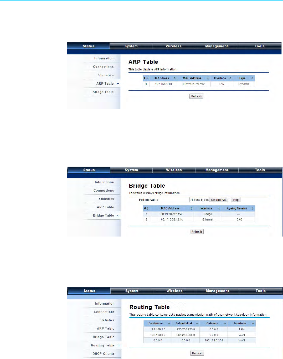
7.4 View ARP Table
Open "ARP Table" in "Status" as below. Click "Refresh" to view current table.
Figure 7.5 ARP Table
7.5 View Bridge Table
Open "Bridge Table" in "Status" as below. Click "Refresh" to view current connected
status..
Figure 7.6 Bridge Table
7.6 View Routing Table
Available in Router mode, the routing table shows the current route information.
Figure 7.7 Routing Table

55 EKI-6331AN-BE/EKI-6332GN-AE User Manual
Chapter 7 Status
7.7 View Active DHCP Client Table
Available in Router mode, the DHCP allows to check the assigned IP address, MAC
address and time expired for each DHCP leased client. Click "Refresh" to view cur-
rent table.
Figure 7.8 DHCP Client Table

EKI-6331AN-BE/EKI-6332GN-AE User Manual 56

Chapter 8
8Troubleshooting

EKI-6331AN-BE/EKI-6332GN-AE User Manual 58
This chapter provides troubleshooting procedures for basic problems with EKI-
6332GN-AE/EKI-6331AN-BE. For warranty assistance, contact your service provider
or distributor for the process.
Q1. How to know the MAC address of EKI-6332GN-AE/EKI-6331AN-BE?
MAC Address distinguishes itself by the unique identity among network devices.
There are two ways available to know it.
• Each device has a label posted with the MAC address. Please refer below.
Figure 8.1 MAC Address
• On EKI-6332GN-AE/EKI-6331AN-BE Web-based management interface, you
can view the MAC Address from “View Basic Information”.
Q2. What if I would like to reset the unit to default settings?
You may restore factory default settings in “Configuration File” from “Manage-
ment”.
Q3. What if I would like to backup and retrieve my configuration settings?
You may do the backup by generating a configuration file or retrieve the settings
you have backed up previously in “Configuration File” from “Management”.
Q4. What if I can not access the Web-based management interface?
Please check the followings:
• Check whether the power supply is OK; Try to power on the unit again.
• Check whether the IP address of PC is correct (in the same network segment
as the unit);
• Login the unit via other browsers such as Firefox.
• Hardware reset the unit.
Q 5. What if the wireless connection is not stable after associating with an AP
under wireless client mode?
• Since EKI-6332GN-AE/EKI-6331AN-BE comes with a built-in directional
antenna, it is recommended make EKI-6332GN-AE/EKI-6331AN-BE face to
the direction where the AP is to get the best connection quality.
• In addition, you can start “Site Survey” in “Wireless Basic Settings” to check
the signal strength. If it is weak or unstable (The smaller the number is, the
weaker the signal strength is.), please join other available AP for better con-
nection.

Appendix A
AASCII

EKI-6331AN-BE/EKI-6332GN-AE User Manual 60
A.1 ASCII
WEP can be configured with a 64-bit, 128-bit or 152-bit Shared Key (hexadecimal
number or ACSII). As defined, hexadecimal number is represented by 0-9, A-F or a-f;
ACSII is represented by 0-9, A-F, a-f or punctuation. Each one consists of two-digit
hexadecimal.
Table A.1: ASCII
ASCII
Character Hex
Equivalent ASCII
Character Hex
Equivalent ASCII
Character Hex
Equivalent ASCII
Character Hex
Equivalent
!21939Q51i 69
"22:3AR52j 6A
#23; 3BS53k 6B
$24<3CT54l 6C
%25= 3DU 55m 6D
&26>3EV 56n 6E
‘27?3FW57o6F
(28@40X58p70
)29A41Y59q71
*2AB42Z5Ar 72
+2BC43[ 5Bs 73
,2CD44\ 5Ct 74
-2DE45] 5Du75
.2EF46^5Ev76
/2FG47_5Fw77
030H48` 60x 78
131I 49a 61y 79
232J4Ab 62z 7A
333K4Bc 63{ 7B
434L4Cd 64| 7C
535M4De 65} 7D
636N4Ef 66~ 7E
737O4Fg 67
838P50h 68

61 EKI-6331AN-BE/EKI-6332GN-AE User Manual
Appendix A ASCII

www.advantech.com
Please verify specifications before quoting. This guide is intended for reference
purposes only.
All product specifications are subject to change without notice.
No part of this publication may be reproduced in any form or by any means,
electronic, photocopying, recording or otherwise, without prior written permis-
sion of the publisher.
All brand and product names are trademarks or registered trademarks of their
respective companies.
© Advantech Co., Ltd. 2016