Advantech Co IVU4000 Computer User Manual Manual
Advantech Co Ltd Computer Manual
UserManual.wiki
>
Advantech Co
>
IVU4000 User Manual
>
Manual
Contents
1.
User Manual
2.
Users Manual
3.
Manual
Manual
Navigation menu
Upload a User Manual
Namespaces
Wiki Guide
HTML
PDF
Info
Views
User Manual
Discussion / Help
Navigation
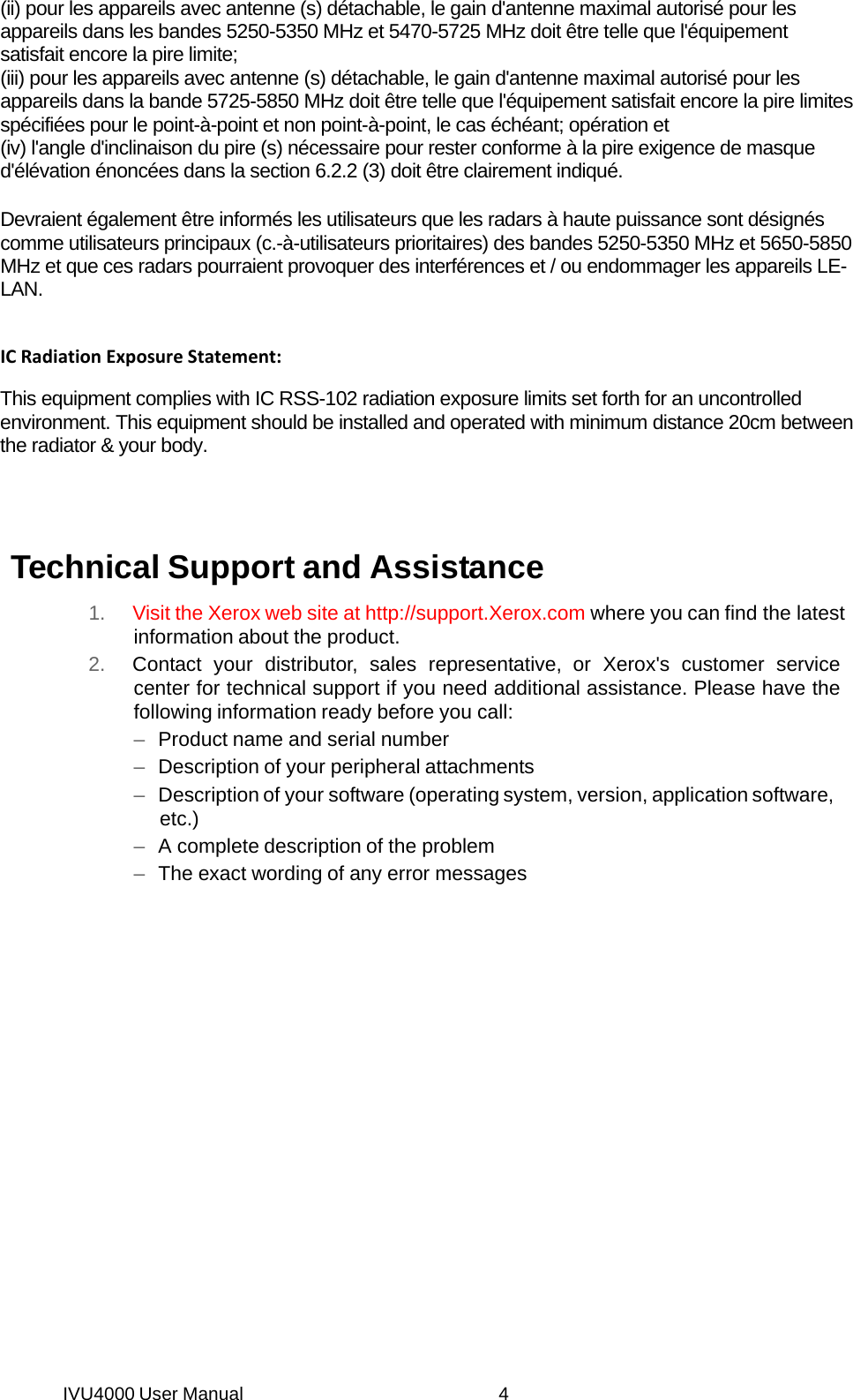
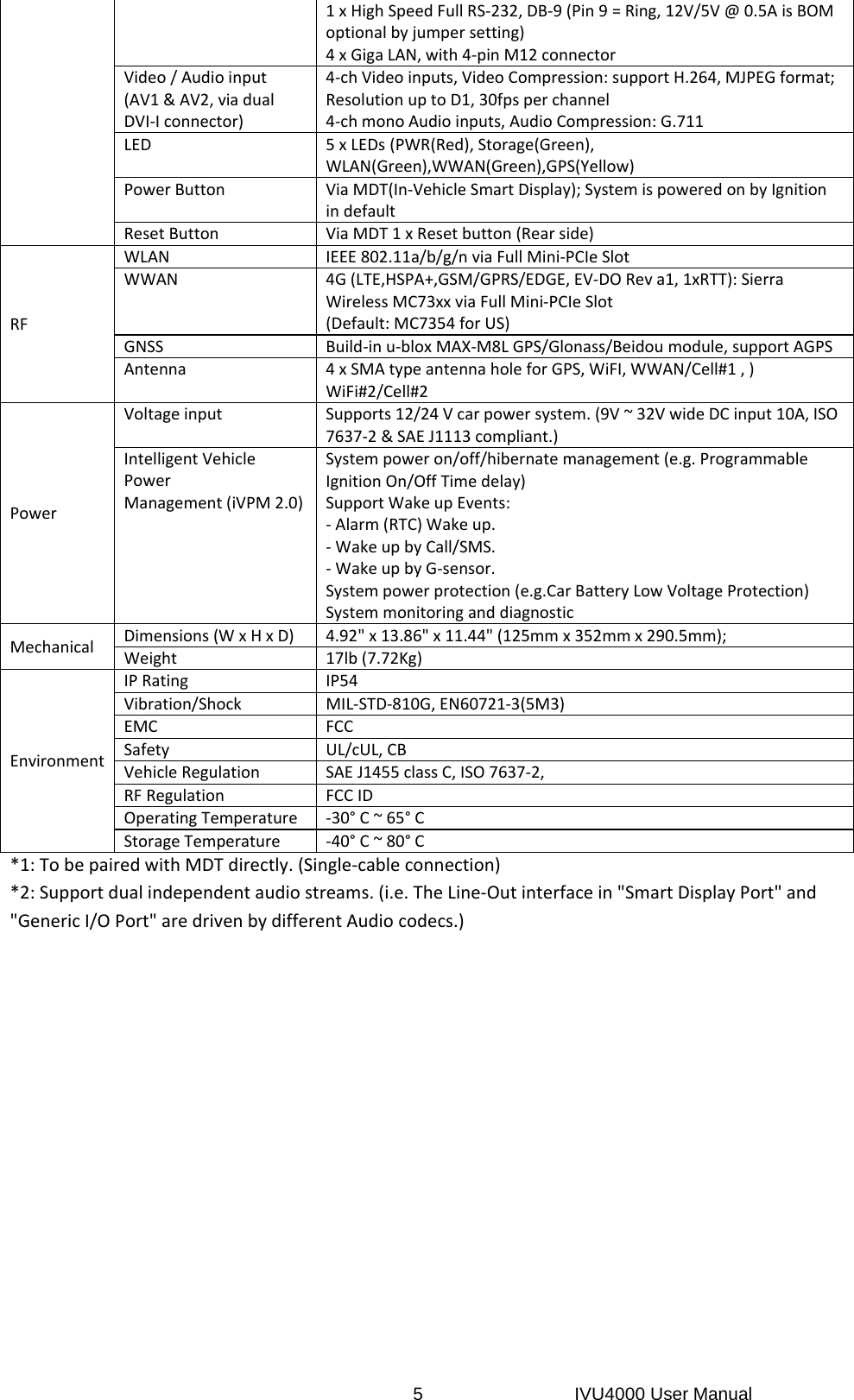
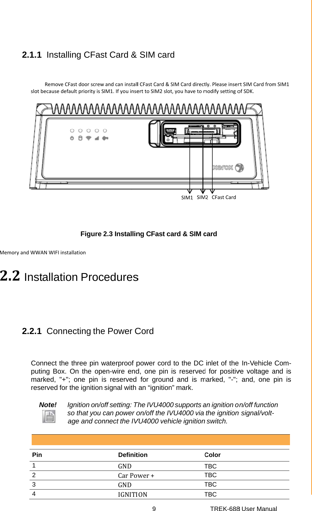
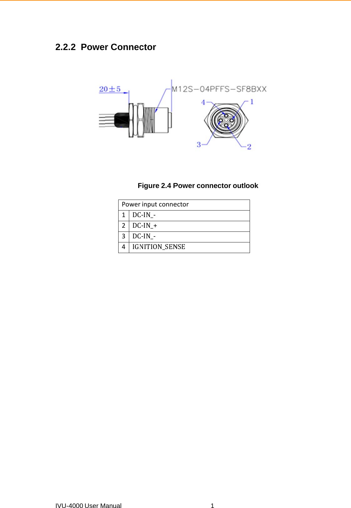

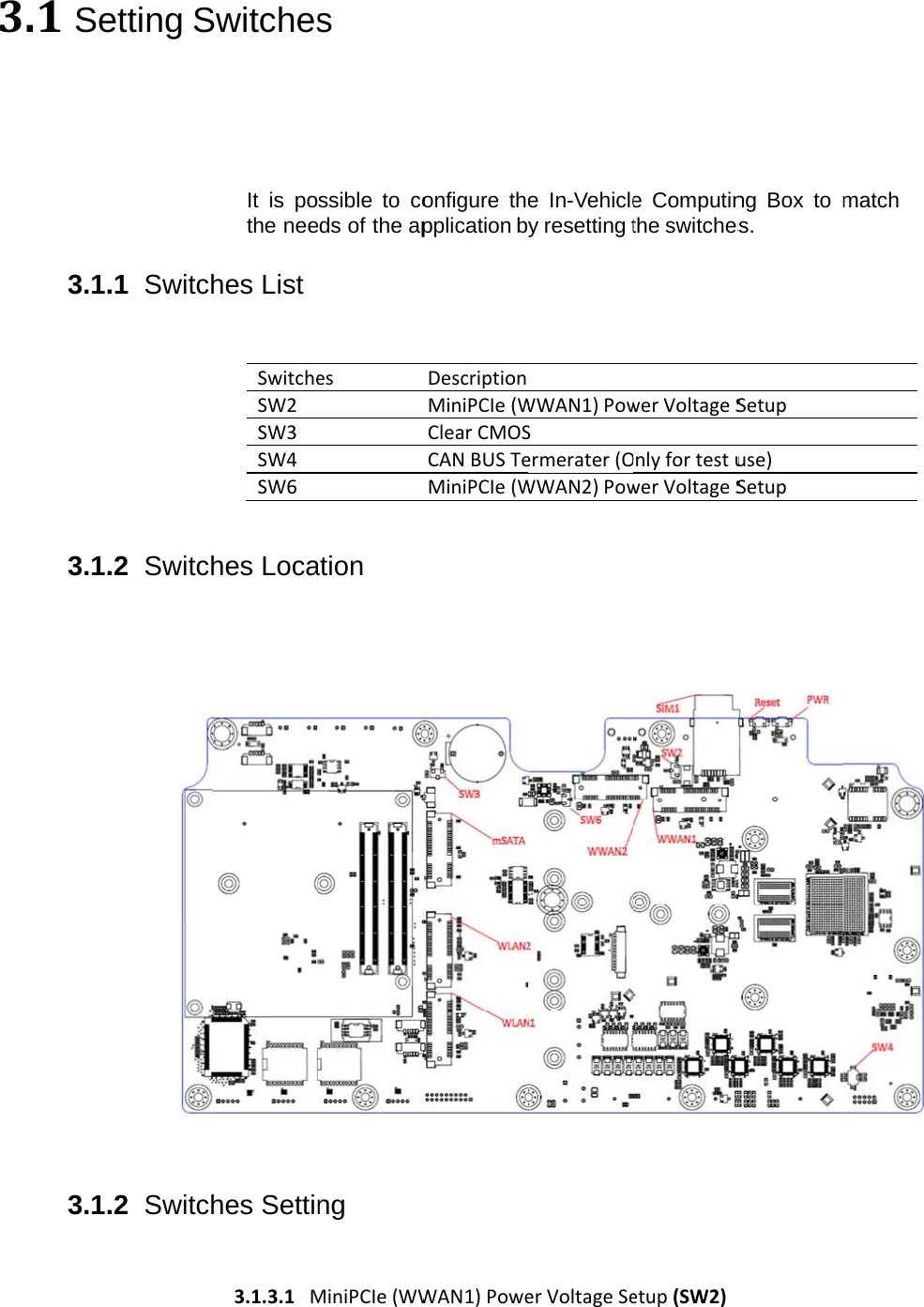
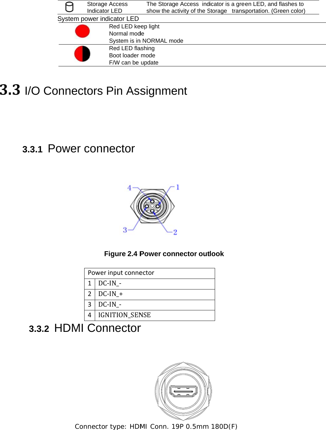
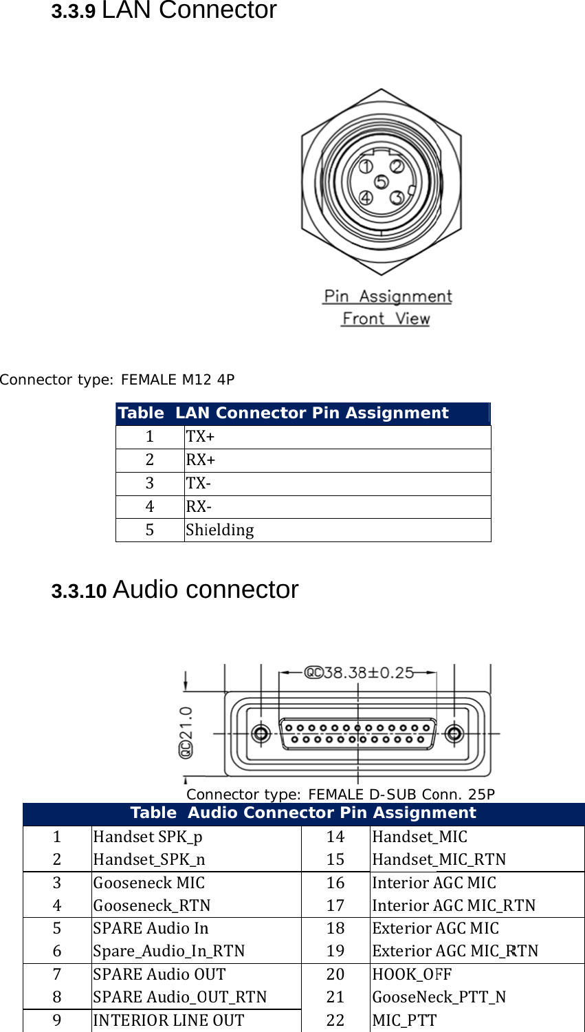
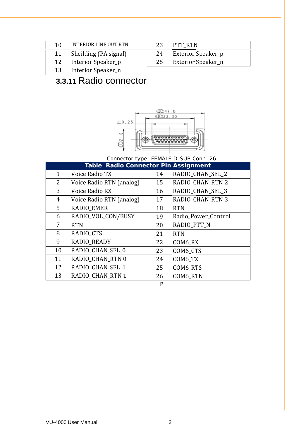
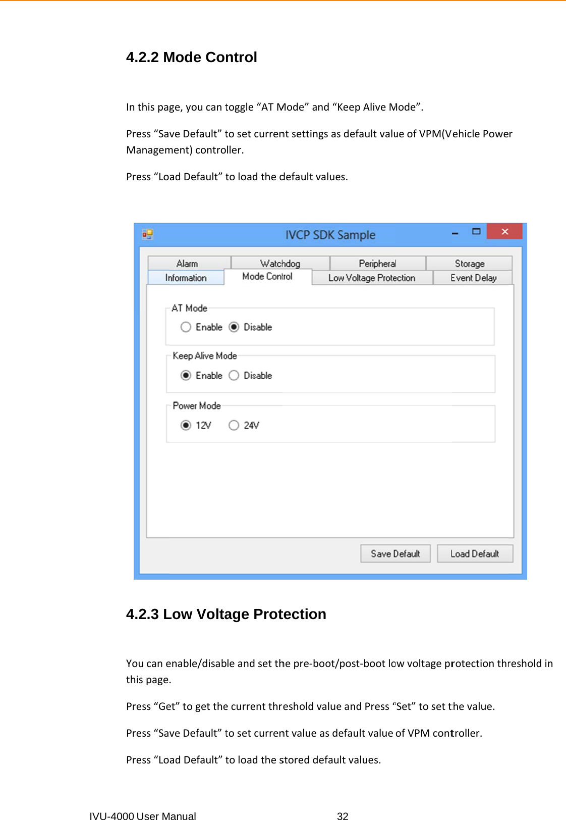
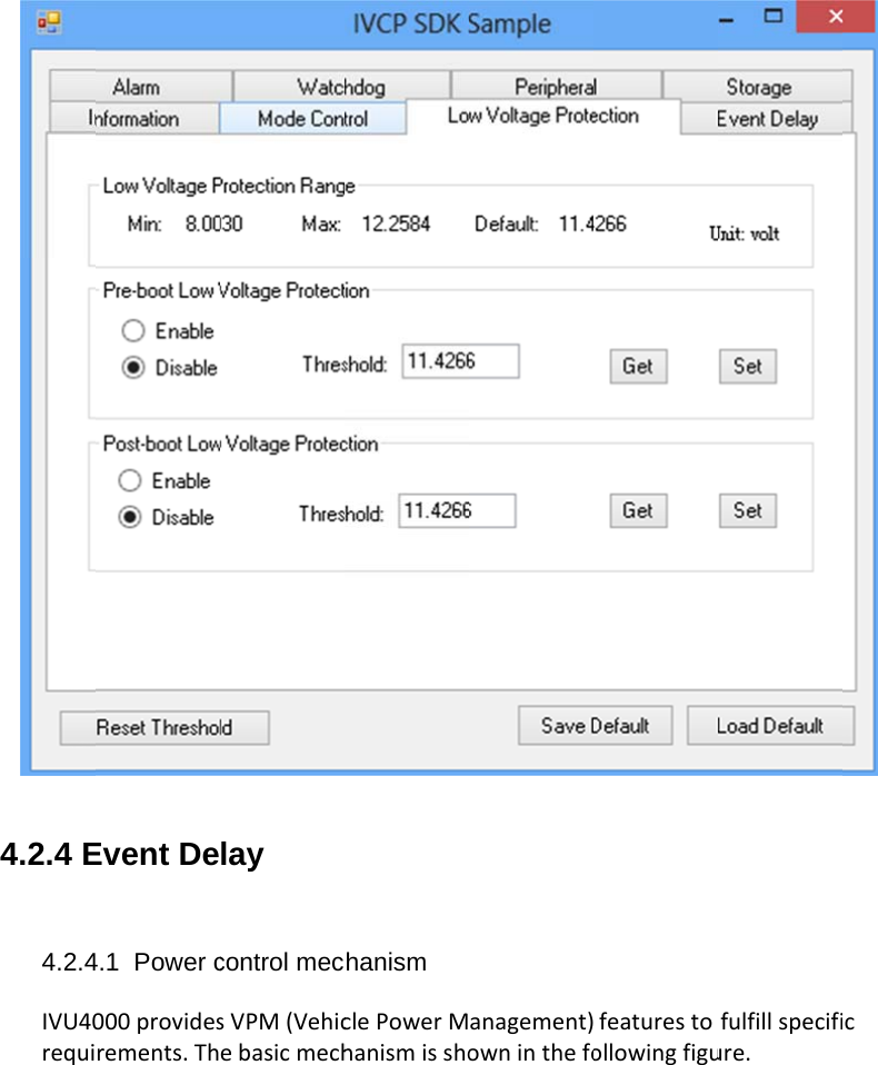
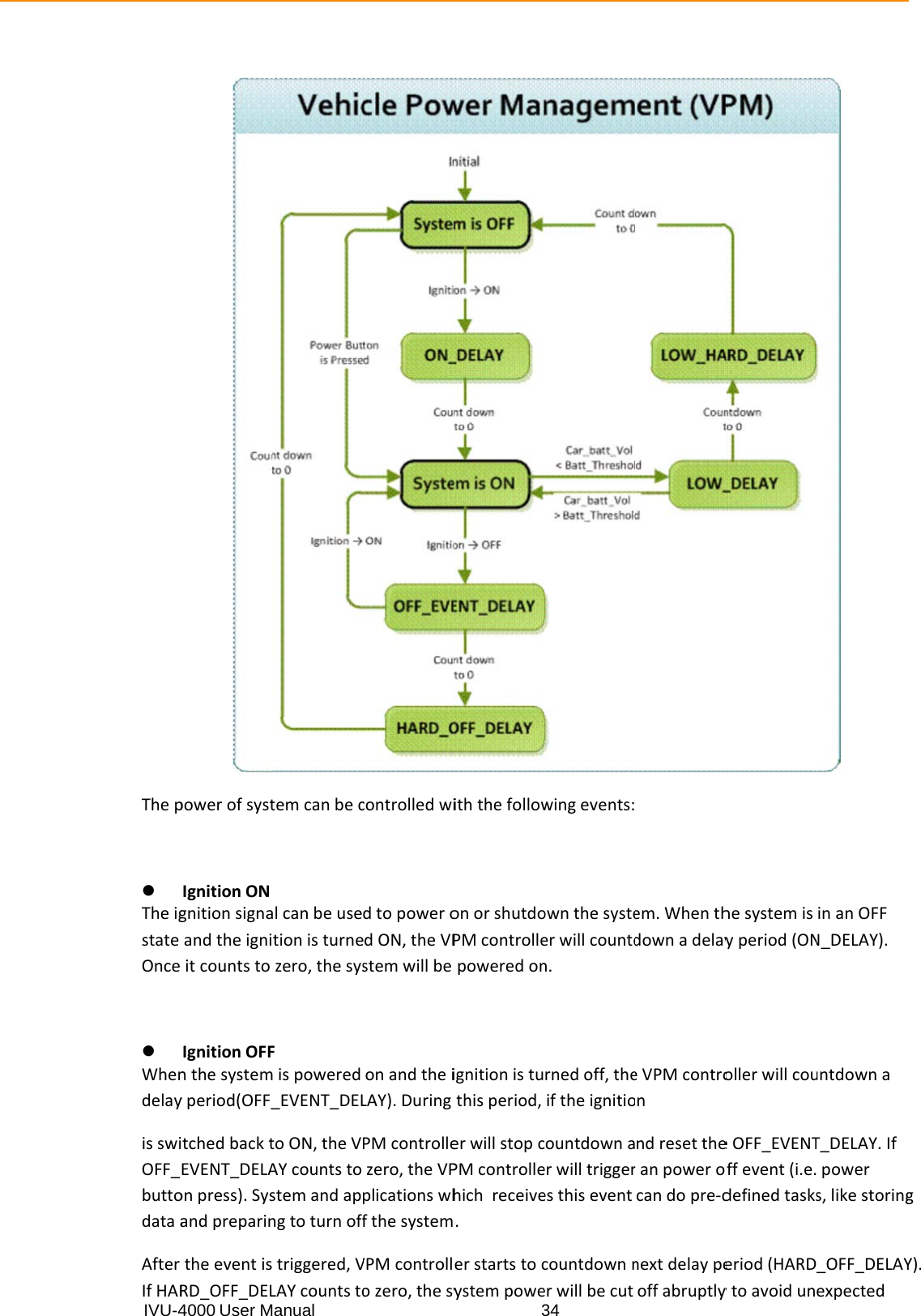
![IVU-4Pin 1 2 3 4 5 6 7 8 9 10 4000 User MSignal DepTTMDTTTMDTTTMDT3.3.3 MDPin 1 3 5 7 9 11 13 15 17 19 21 23 Manual Tablepiction TMDS_DATADS_DATA2+ TMDS_DATATMDS_DATADS_DATA1 STMDS_DATATMDS_DATADS_DATA0 sTMDS_DATATMDS ClocDT ConSignaLVDSLVDSLVDSVdd_eLVDSLVDSLVDSBTN_RUSB_PUSB_RAUD_SPK HDMI ConA2+ Shield A2- A1+ Shield A1- A0+ shield A0- ck nnectoral S1_p/[D0] S1_RTN S1_n en S3_p/[D3] S3_RTN S4_n RST P RTN _RTN nector Pin APin Si111213141516171819 r (DVI-I1Assignmentgnal DepictiTMDTHDMH) Pin 2 4 6 8 10 12 14 16 18 20 22 24 t ion S_Clock ShiMDS Clock- CEC Reserved SCL SDAA GND MI_Power(5VHDMI_HPD Signal LVDS1_nLVDS2_pMDT_DETVBL_en LVDS3_nLVDS4_pLVDS4_RRTN USB_N RTN Cover_MAUD_RTNield V) n p/[D1] T# n p/[CLK] RTN IC N](https://usermanual.wiki/Advantech-Co/IVU4000.Manual/User-Guide-3072225-Page-28.png)