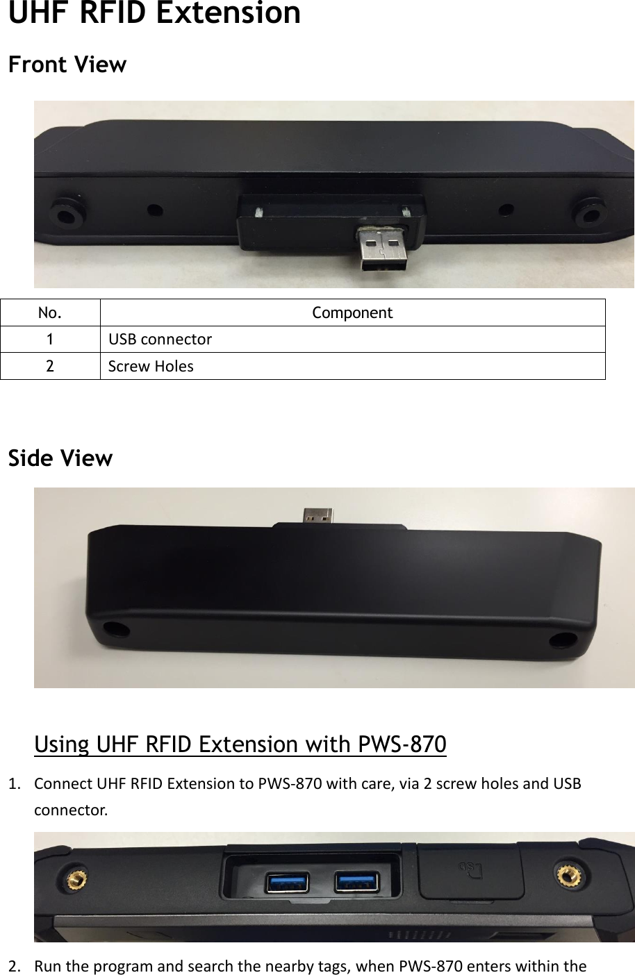
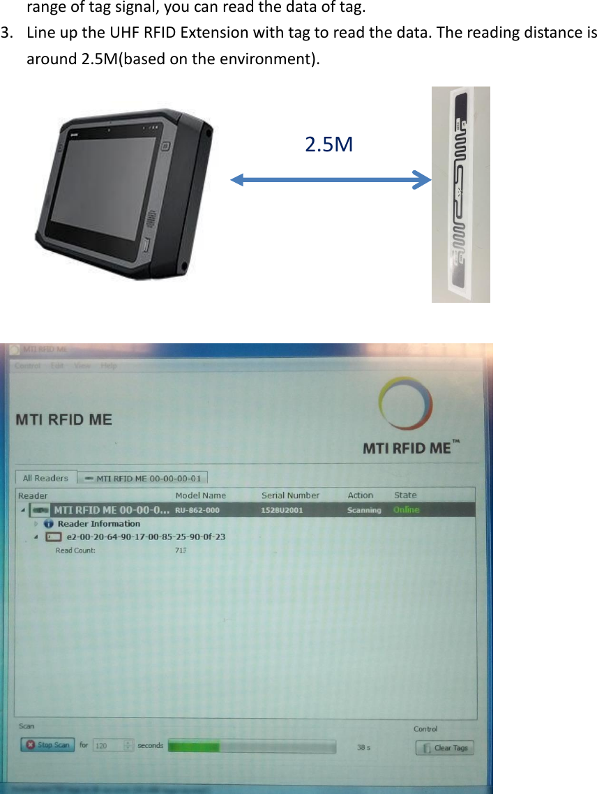
Advantech Co TPC130UHFRFID UHF RFID User Manual
Advantech Co Ltd UHF RFID
UserManual.wiki
>
Advantech Co
>
TPC130UHFRFID User Manual
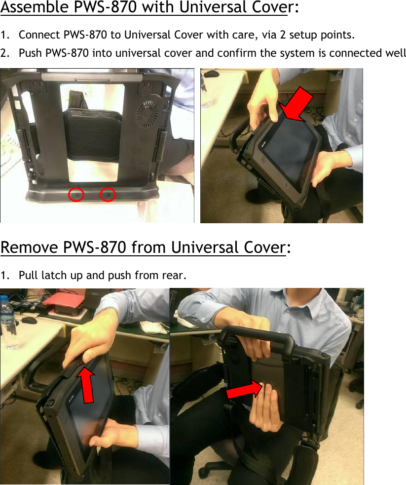
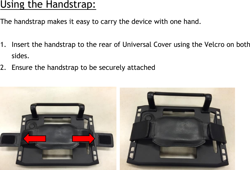
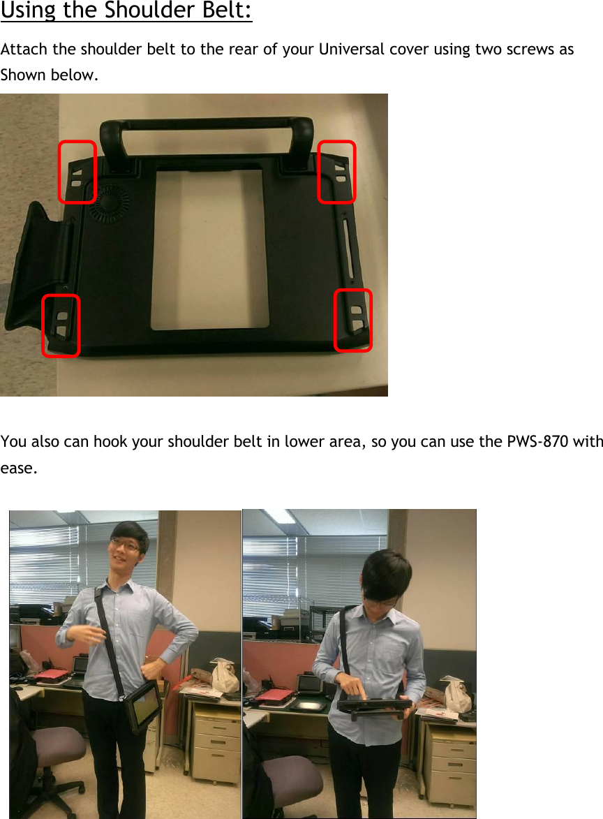
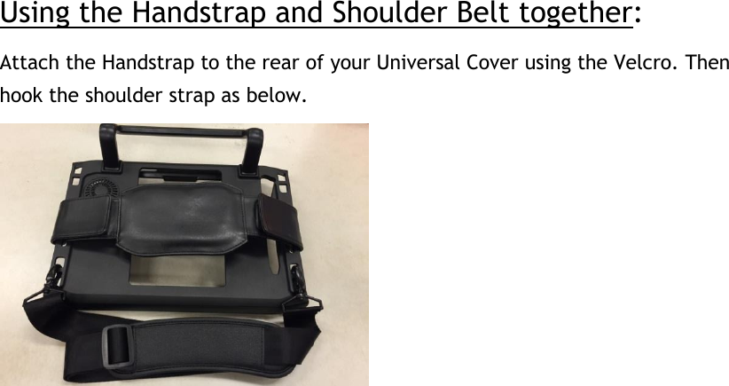
User Manual
Navigation menu
Upload a User Manual
Namespaces
Wiki Guide
HTML
PDF
Info
Views
User Manual
Discussion / Help
Navigation