Advantech Co TPC130UHFRFID UHF RFID User Manual
Advantech Co Ltd UHF RFID
User Manual
User Manual
PWS-870
Fully-Rugged Tablet PC
Optional Accessories
Copyright
The documentation and the software included with this product are copyrighted 2012
by Advantech Co., Ltd. All rights are reserved. Advantech Co., Ltd. reserves the right
to make improvements in the products described in this manual at any time without
notice. No part of this manual may be reproduced, copied, translated or transmitted
in any form or by any means without the prior written permission of Advantech Co.,
Ltd. Information provided in this manual is intended to be accurate and reliable.
However,
Advantech Co., Ltd. assumes no responsibility for its use, nor for any infringements
of the rights of third parties, which may result from its use.
Acknowledgements
All other product names or trademarks are properties of their respective owners.

Declaration of Conformity
CE Conformity Statement
Radio products with the CE alert marking comply with the R&TTE Directive (1999/5/
EC) issued by the Commission of the European Community. Compliance with this
directive implies conformity to the following European Norms (in brackets are the
equivalent international standards)
EN 60950-1 (IEC60950-1) - Product Safety
Products that contain the radio transmitter are labeled with CE alert marking and may
also carry the CE logo.
FCC Compliance Statement
This device complies with part 15 of the FCC Rules. Operation is subject to the
following
two conditions:
1. This device may not cause harmful interference;
2. This device must accept any interference received, including interference that may
cause undesired operation.
Caution! Exposure to Radio Frequency Radiation.
The radiated output of this device is far below the FCC radio frequency
exposure limits. Nevertheless, the device shall be used in such a manner
that the potential for human contact during normal operation is minimized.
When connecting an external antenna to the device, the antenna
shall be placed in such a manner to minimize the potential for human
contact during normal operation. In order to avoid the possibility of
exceeding the FCC radio frequency exposure limits, human proximity to
the antenna shall not be less than 20cm (8inches) during normal operation.
This equipment has been tested and found to comply with the limits for a Class B
digital device, pursuant to part 15 of the FCC Rules. These limits are designed to
provide reasonable protection against harmful interference in a residential installation.
This equipment generates, uses and can radiate radio frequency energy. If this
equipment does cause harmful interference to radio or television reception, which
can be determined by turning the equipment off and on, the user is encouraged to try
and correct the interference by one or more of the following measures:
However, there is no guarantee that interference will not occur in a particular
installation. If this equipment does cause harmful interference to radio or television

reception, which can be determined by turning the equipment off and on, the user is
encouraged to try to correct the interference by one or more of the following
measures:
Reorient or relocate the receiving antenna
Increase the separation between the equipment and receiver
Connect the equipment into an outlet on a circuit different from that to which
the receiver is connected
Consult the dealer or an experienced computer technician for help
Technical Support and Assistance
1. Visit the Advantech website at http://support.advantech.com where you can find
the latest information about the product.
2. Contact your distributor, sales representative, or Advantech's customer service
center for technical support if you need additional assistance. Please have the
following information ready before you call:
– Product name and serial number
– Description of your peripheral attachments
– Description of your software (operating system, version, application software,
etc.)
– A complete description of the problem
– The exact wording of any error messages
Safety Instructions
Use the following safety guidelines to help protect yourself and PWS-870
Do not attempt to service the PWS-870 yourself. Always follow installation
instructions closely.
Be sure that nothing rests on the AC adapter's power cable and that the cable is
not located where it can be tripped over or stepped on.
Do not cover the AC adaptor with papers or other items that will reduce cooling;
also, do not use the AC adapter while it is inside a carrying case.
Use only the AC adapter, power cord, and batteries that are approved for use
with this PWS-870. Use of another type of battery or AC adapter may cause risk
of fire or explosion.
If you use an extension cable with the AC adapter, ensure that the total ampere
rating of the products plugged in to the extension cable does not exceed the
ampere rating of the extension cable.
When you move the PWS-870 between environments with very different
temperature and/ore humidity ranges, condensation may form on or within the
PWS-870. To avoid damaging the PWS-870, allow sufficient time for the
moisture to evaporate before using the PWS-870.
When you disconnect a cable, pull on its connector or on its strain relief loop, not
on the cable itself. As you pull out the connector, keep it evenly aligned to avoid
bending any connector pins. Also, before you connect a cable make sure both
connectors are correctly oriented and aligned.
Chapter 1
Universal Cover, Handstrap and
Shoulder Belt
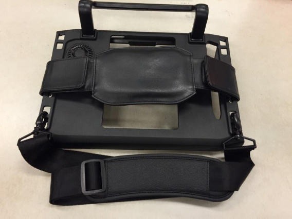
Universal Cover, Handstrap and Shoulder Belt are provided to carry your Tablet PC
securely and safely. You can use the Handstrap and Shoulder Strap we provide
separately or together to carry the PWS-870 either indoors and outdoors.
Exploring the Universal Cover, Handstrap and
Shoulder Belt
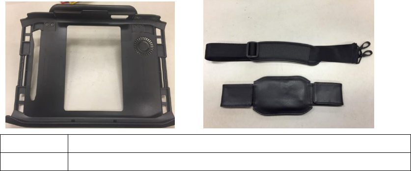
Front View
No.
Component
1
Hook Point
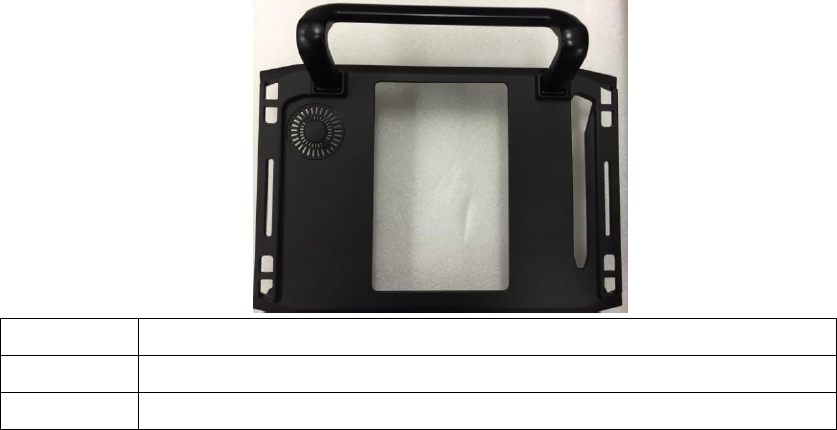
Rear View
No.
Component
2
HANDGRIP
3
Hook Point
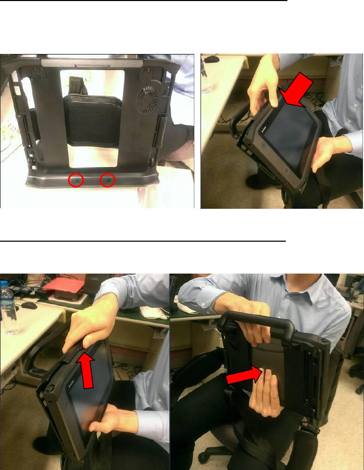
Assemble PWS-870 with Universal Cover:
1. Connect PWS-870 to Universal Cover with care, via 2 setup points.
2. Push PWS-870 into universal cover and confirm the system is connected well
Remove PWS-870 from Universal Cover:
1. Pull latch up and push from rear.
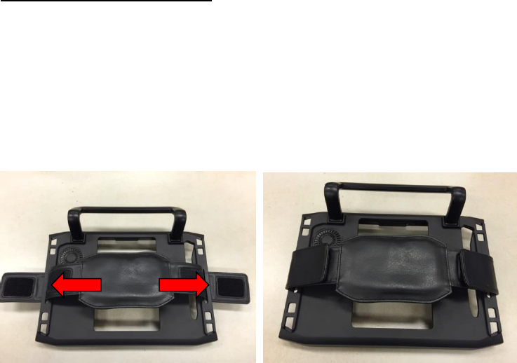
Using the Handstrap:
The handstrap makes it easy to carry the device with one hand.
1. Insert the handstrap to the rear of Universal Cover using the Velcro on both
sides.
2. Ensure the handstrap to be securely attached
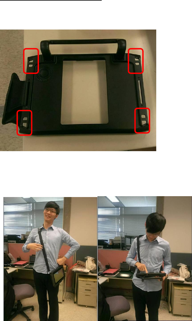
Using the Shoulder Belt:
Attach the shoulder belt to the rear of your Universal cover using two screws as
Shown below.
You also can hook your shoulder belt in lower area, so you can use the PWS-870 with
ease.
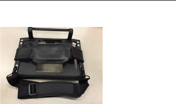
Using the Handstrap and Shoulder Belt together:
Attach the Handstrap to the rear of your Universal Cover using the Velcro. Then
hook the shoulder strap as below.
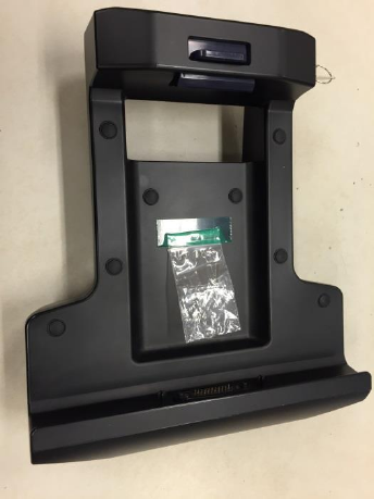
Chapter 2
Vehicle Docking
Vehicle docking could be mounted with the PWS-870 onto any vehicles with
applicable RAM Mount kits. The docking station comes with a lock for theft
deterrence. It offers complete port replication for users to access audio jacks, USB,
RS-232/RS-485, and LAN ports.
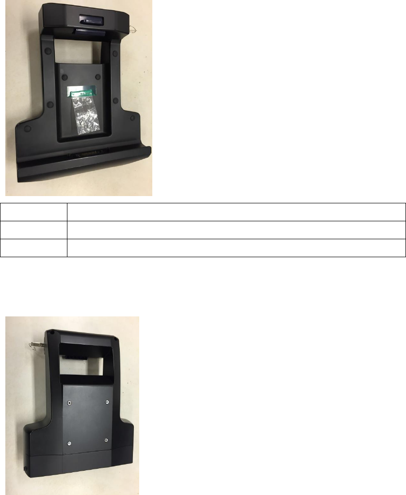
Exploring the Vehicle Docking
Front View
No.
Component
1
Release latch
2
Poco Pin
Rear View
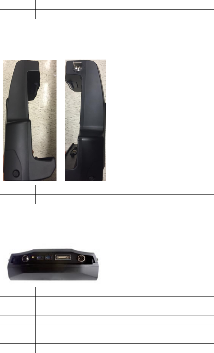
No.
Component
3
Ram Mount Screw hole
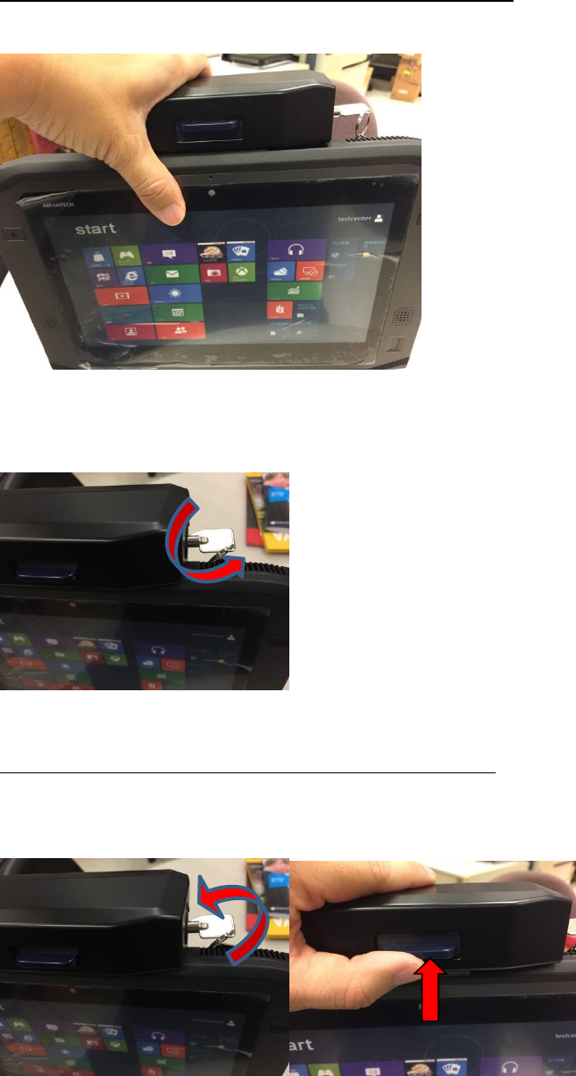
Side View
No.
Component
4
Keyhole
Bottom View
No.
Component
5
Lan 100/100
6
GPS SMA
7
2 x USB Connector (USB 3.0)
8
HDC Connector: RS-232 x1; CAN2.0 x1; DIx2; DOx2; Line-in x1;
Line-out x1
9
DC-in (M12)
Assemble PWS-870 with Vehicle Docking
1. Attach the PWS-870 to the vehicle docking as below.
2. Use the key on the top of the vehicle docking to lock the PWS-870 to avoid theft.
Remove PWS-870 with Vehicle Docking
1. Remove the PWS-870, unlock with key and push the blue latch upward.
The vehicle docking fits many types of RAM Mount kits for installing in different
kinds of vehicles
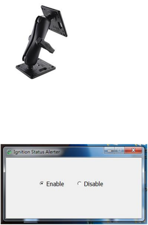
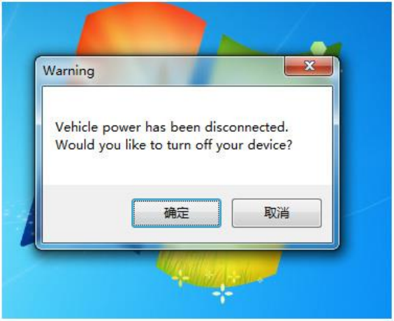
PWS-870 uses a pre-installed “Ignition Status Alert” application. When the vehicle
ignition is turned off, a warning message will pop up to ask the user to turn
off PWS-870. (Some users might continue to use the PWS-870 when the vehicle
is off and this can drain the car battery if the PWS-870 remains connected to the car
battery.)
Chapter 3
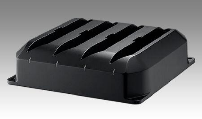
Multiple Battery Charger
Multiple Battery Charger can charge at most 4 batteries, which will provide PWS-870
longer operation time. When the batteries complete charging, Multiple Battery
Charger will stop charging automatically to protect your batteries
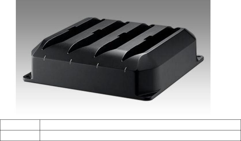
Exploring the Vehicle Docking
Front View
No.
Component
1
Charging status indicator
Side View
No.
Component
2
DC-in
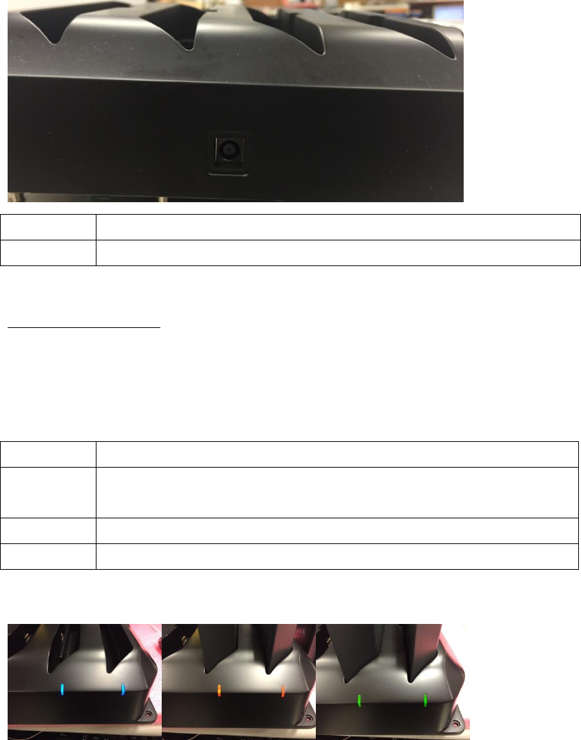
Charging status
Multiple Battery charger can fully charge the battery in around 5 hrs, where the
charging slot can be used individually.
There are 3 kinds of color of indicator
Indicator
Status
Blue
No charging(in case where the battery is placed, please check
whether the battery is connected properly)
Orange
Charging
Green
Charging Completed
Blue Orange Green
Chapter 4
I/O extension, MSR & Smart Card Reader
Extension and UHF RFID Extension
I/O extension provides various I/O ports to connect your devices more conveniently,
which brings out the best performance from PWS-870.
MSR & smart card reader can help user log in easily, or provide limited data access
based on different authorities.
UHF RFID is a wireless data access solution, you just setup the related tag first, then
the device receive the data when PWS-870 approach it.
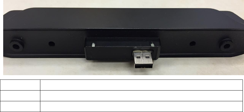
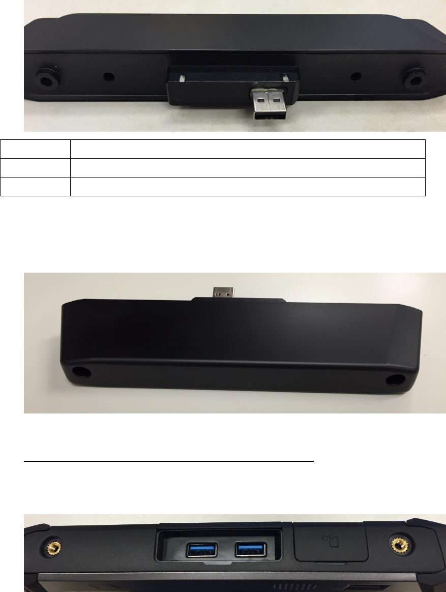
I/O extension
Front View
No.
Component
1
USB connector
2
Screw Holes
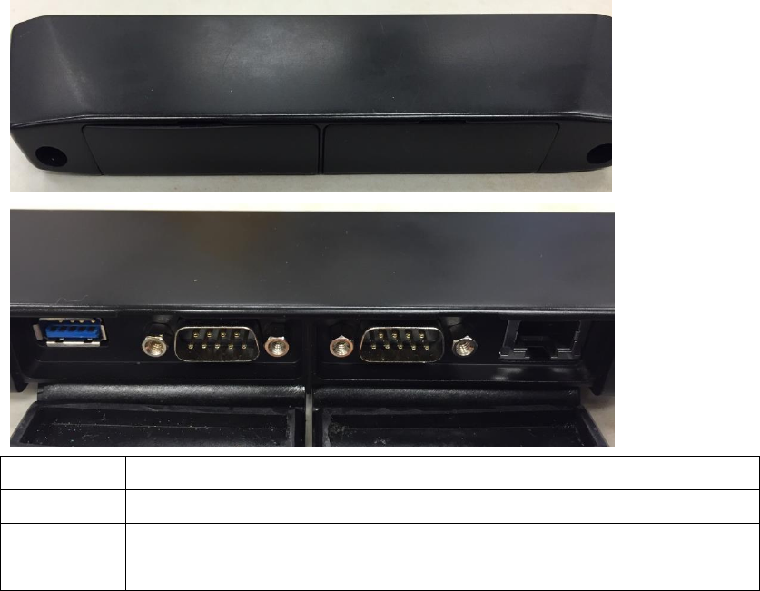
Side View
No.
Component
4
USB Connector (USB 3.0)
5
RS-232(D-Sub 9)
6
Ethernet(RJ45)
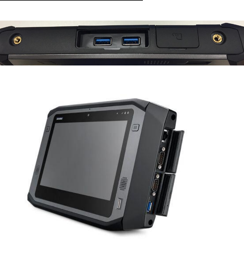
Using I/O Extension with PWS-870
Connect I/O Extension to PWS-870 with care, via 2 screw holes and USB connector.
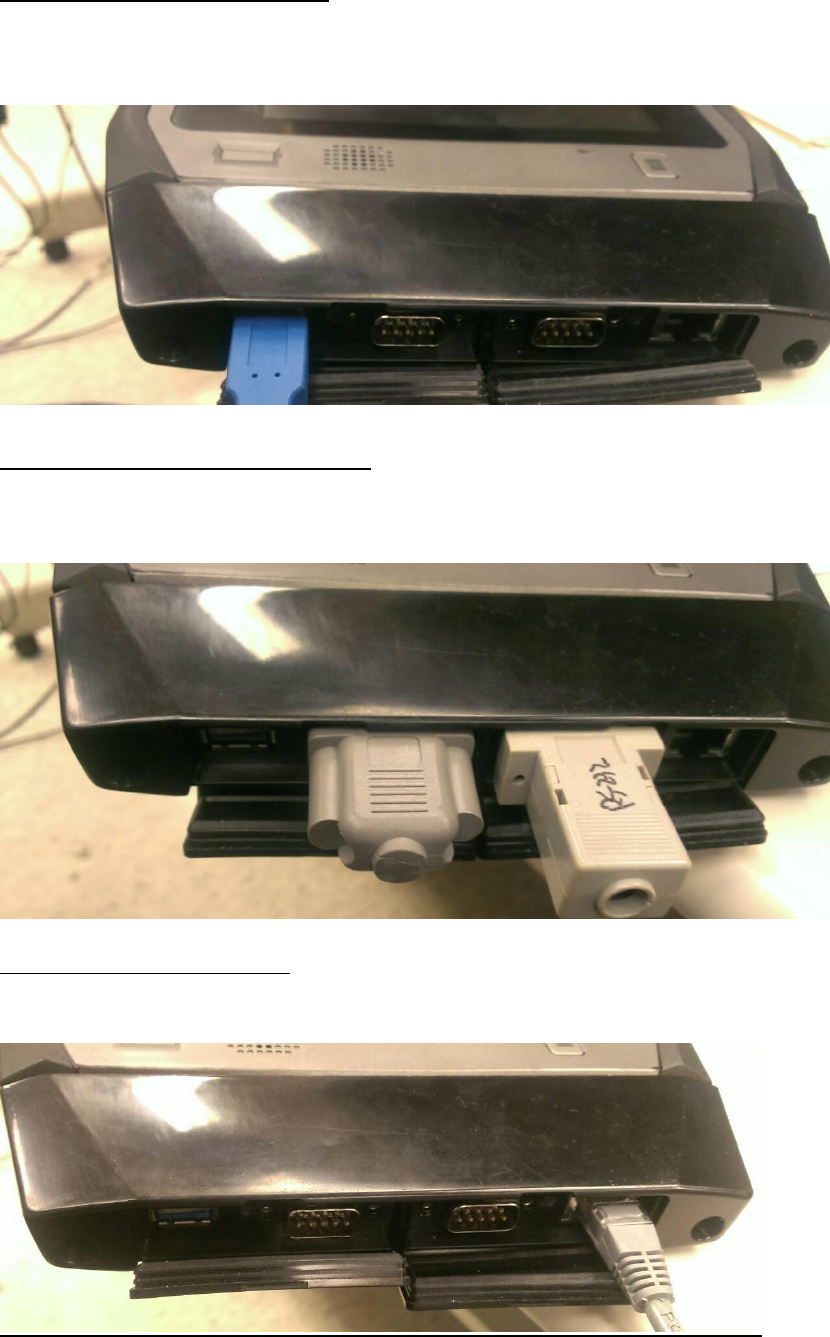
Connecting USB Device
You can connect to various USB devices, such as USB Keyboard and Mouse, besides
you can connect with USB 3.0 device to reach the faster transmission speed as well.
Connecting RS-232 Device
There are 2 sets of RS-232 to connect with CAN box and other device which use
RS-232.
Connecting Network
You can use Lan to connect with network
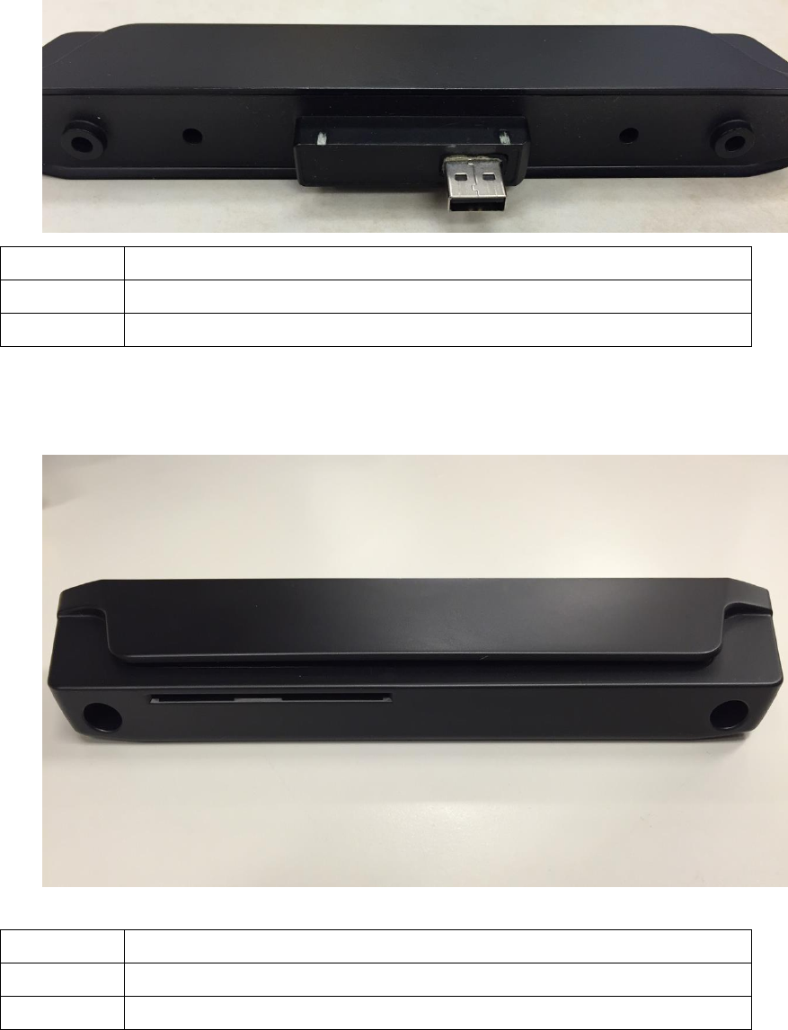
MSR & Smart Card Reader Extension
Front View
No.
Component
1
USB connector
2
Screw Holes
Side View
No.
Component
3
MSR Slot
4
Smart Card Reader Slot
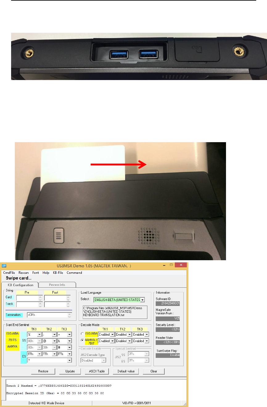
Using MSR & Smart Card Reader Extension with PWS-870
1. Connect MSR & Smart Card Reader Extension to PWS-870 with care, via 2 screw
holes and USB connector.
2. Whether through inserting or swiping the card, user can receive the data in the
card or using it for identification or authorization for further action approved.
MSR
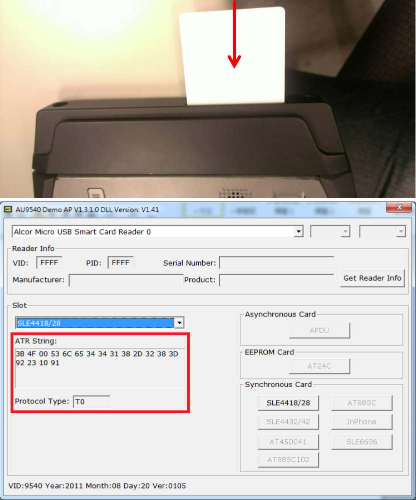
Smart Card Reader
UHF RFID Extension
Front View
No.
Component
1
USB connector
2
Screw Holes
Side View
Using UHF RFID Extension with PWS-870
1. Connect UHF RFID Extension to PWS-870 with care, via 2 screw holes and USB
connector.
2. Run the program and search the nearby tags, when PWS-870 enters within the
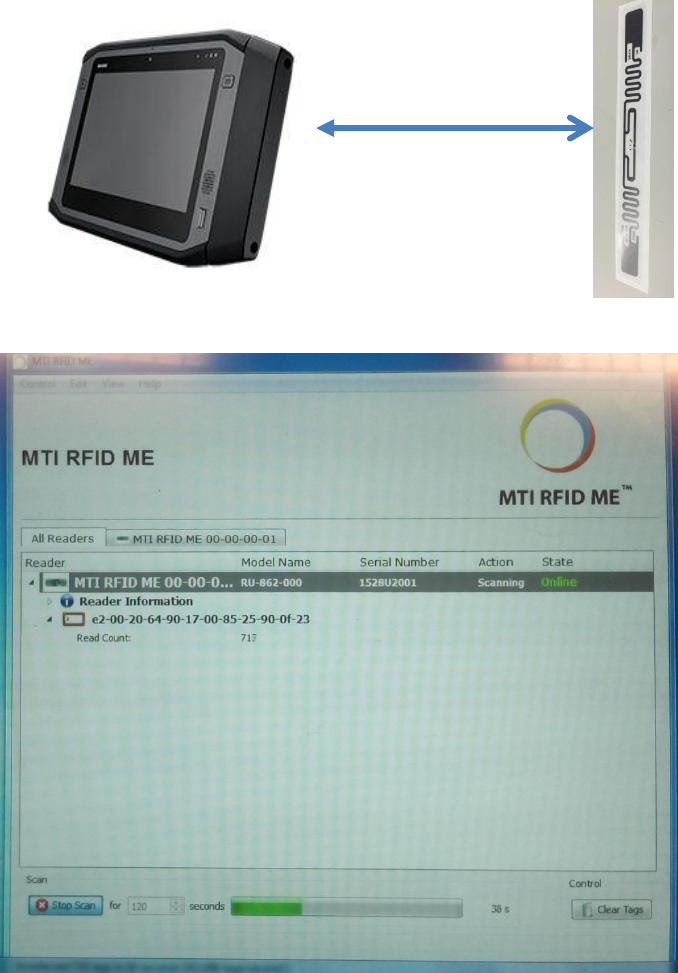
range of tag signal, you can read the data of tag.
3. Line up the UHF RFID Extension with tag to read the data. The reading distance is
around 2.5M(based on the environment).
2.5M