Advantech Co TREK-753 Mobile Data Terminal User Manual V4 12 EV User Manual
Advantech Co Ltd Mobile Data Terminal V4 12 EV User Manual
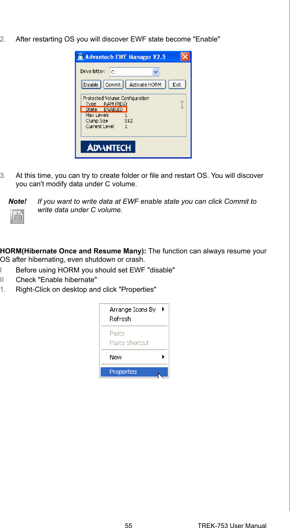
UserManual.wiki
>
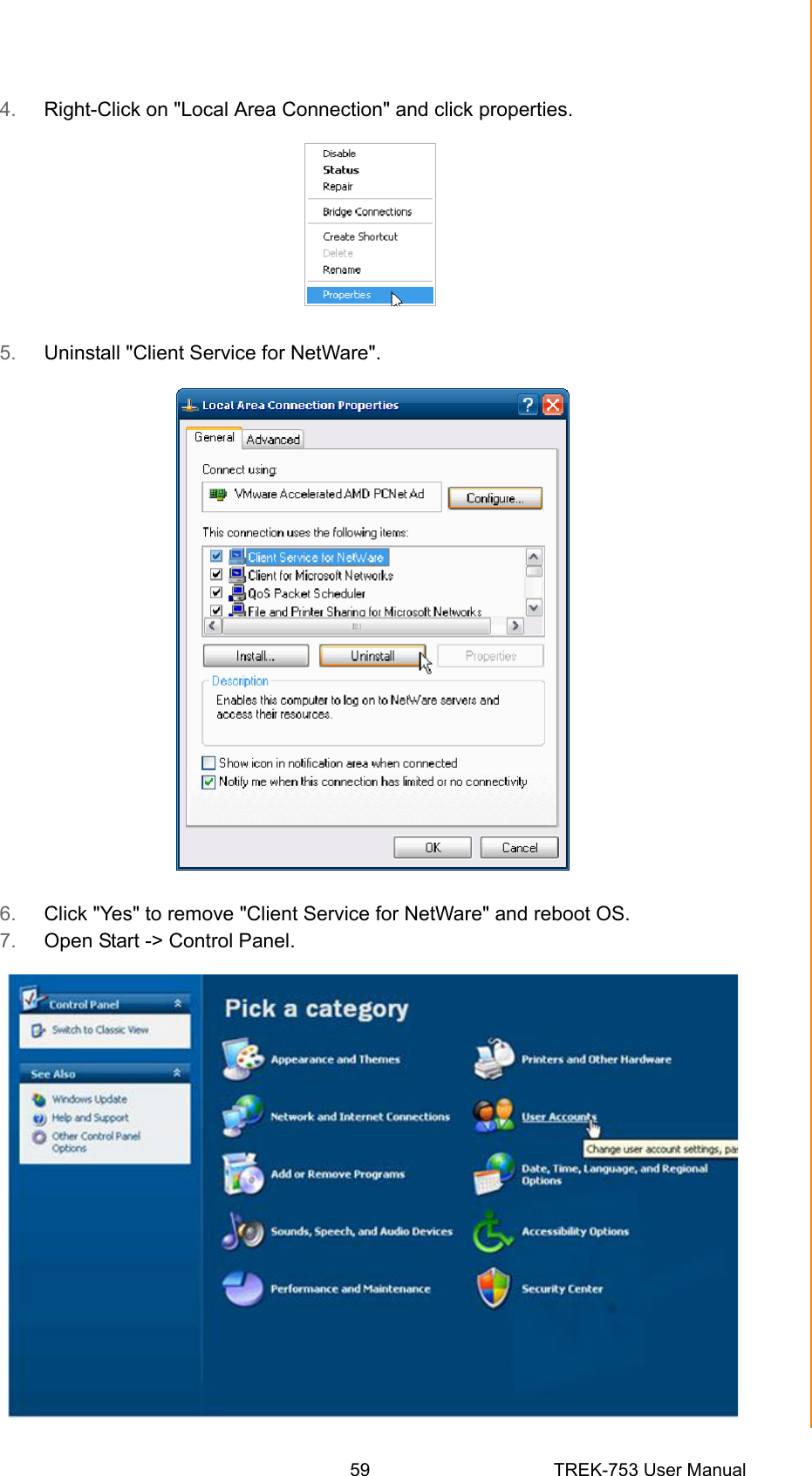
Advantech Co
>
TREK 753 User Manual
User Manual
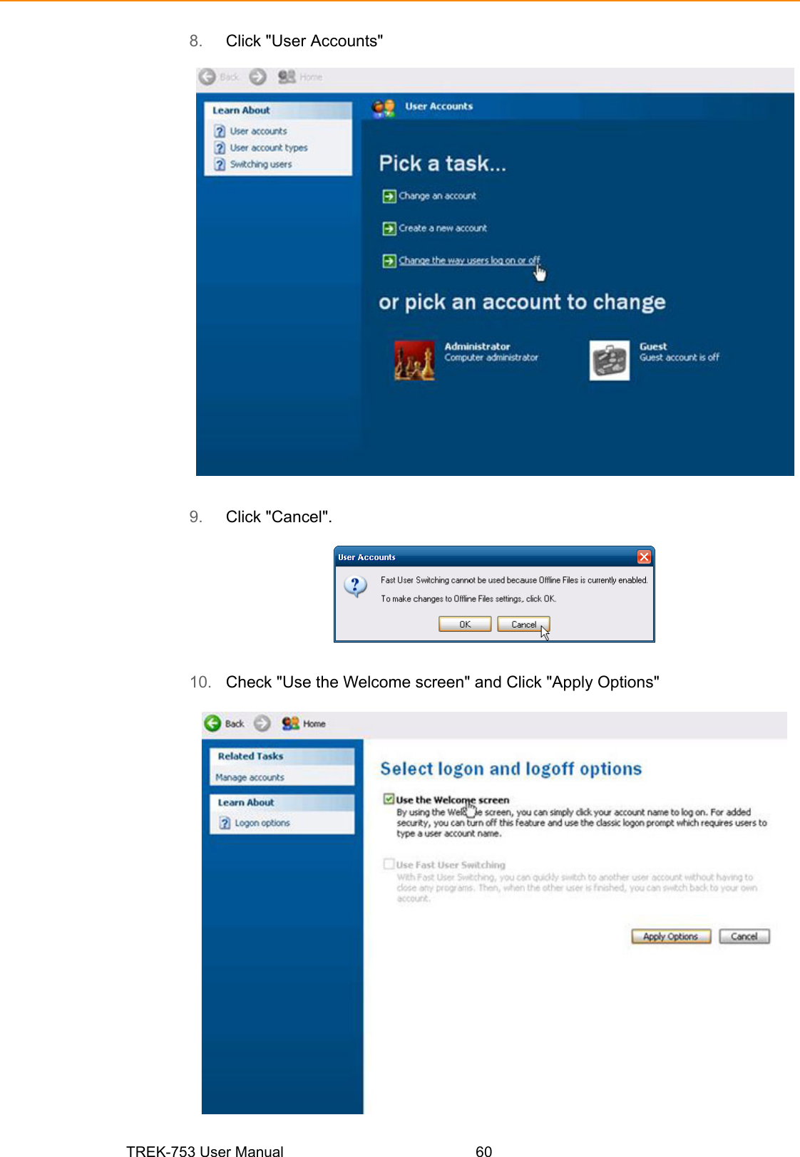
Navigation menu
Upload a User Manual
Namespaces
Wiki Guide
HTML
PDF
Info
Views
User Manual
Discussion / Help
Navigation
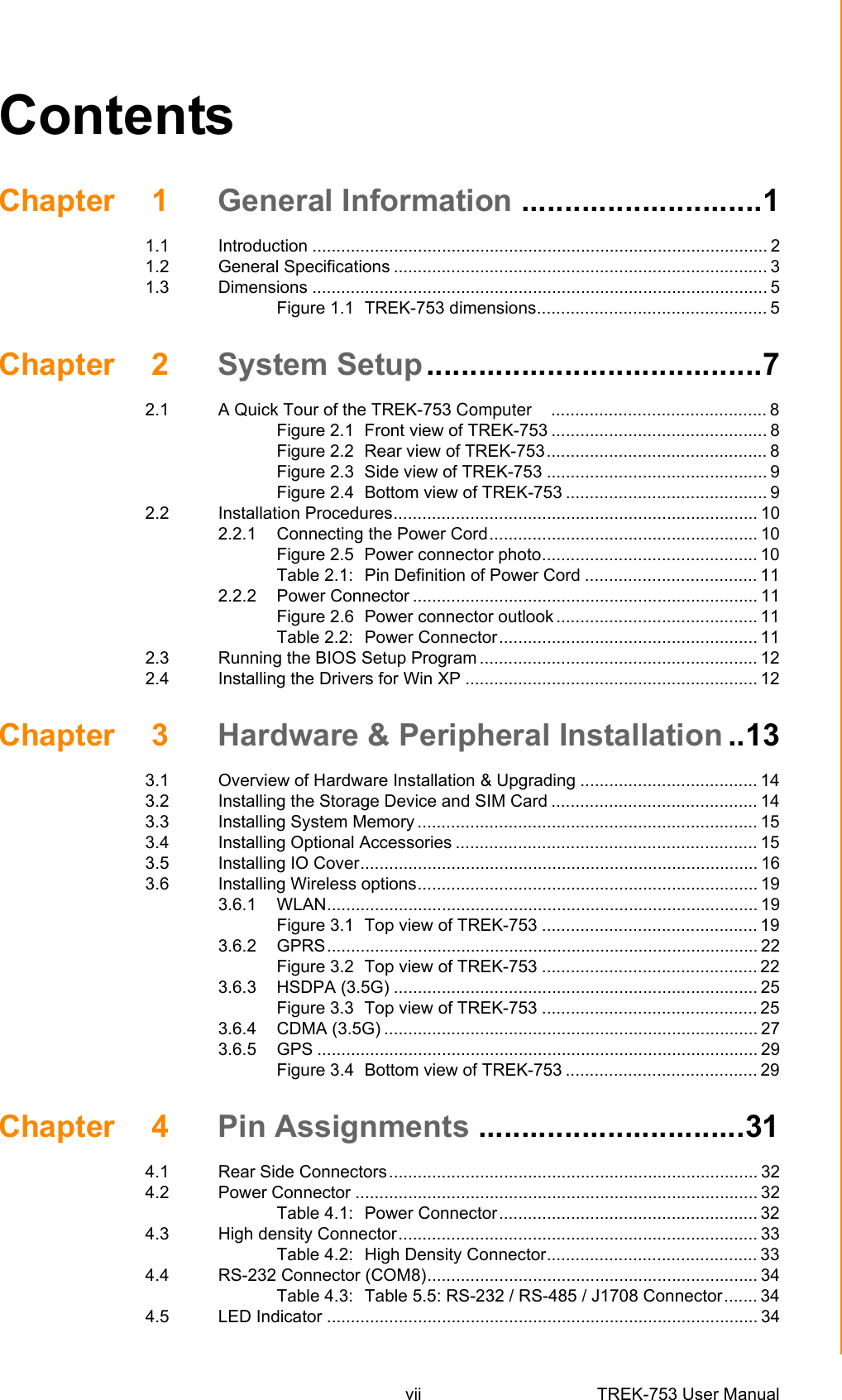

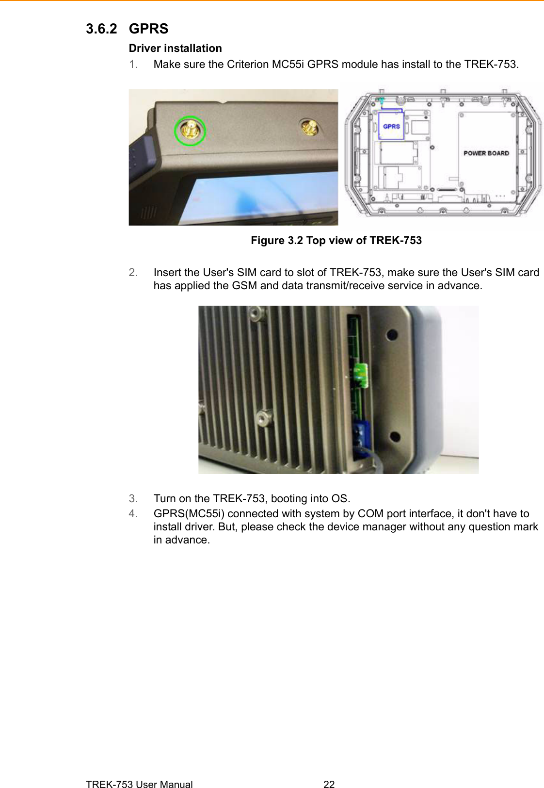
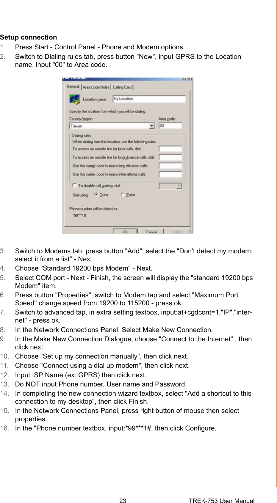
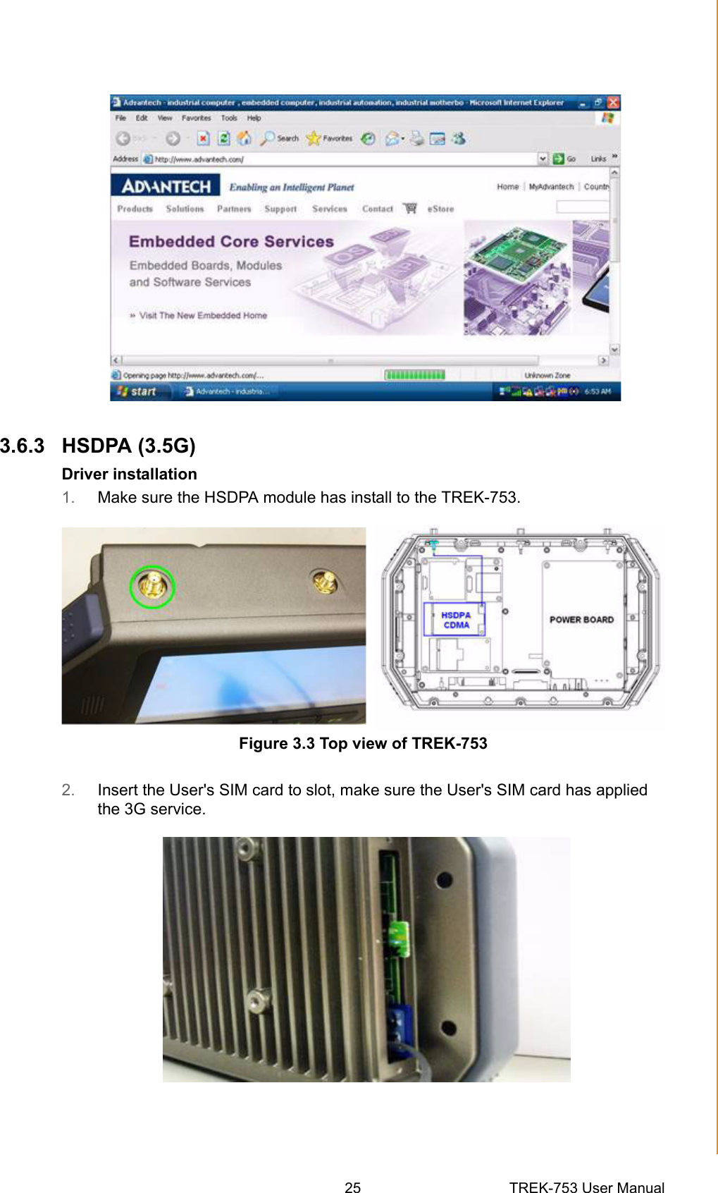

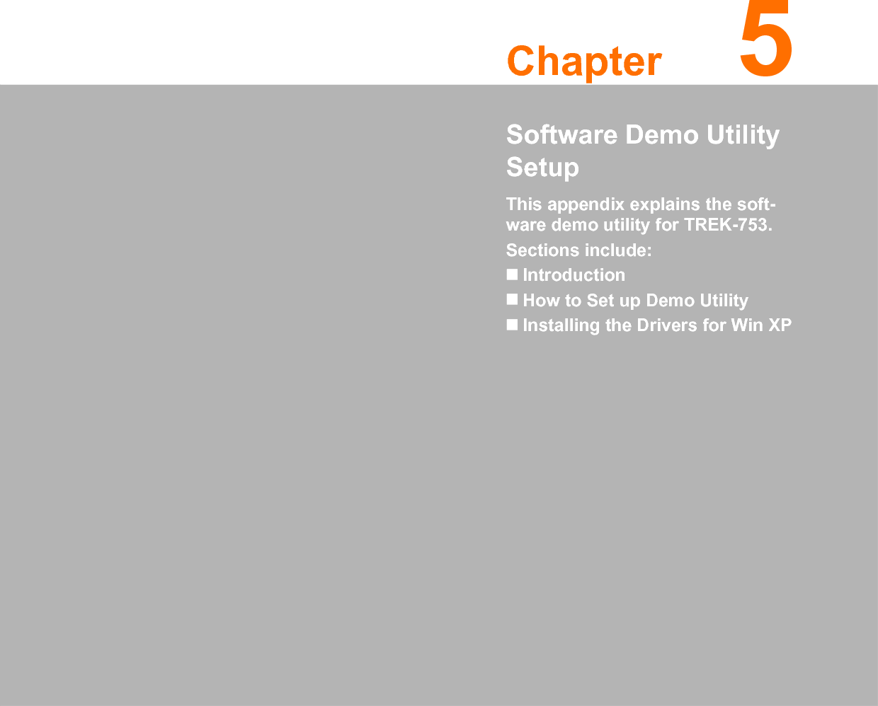
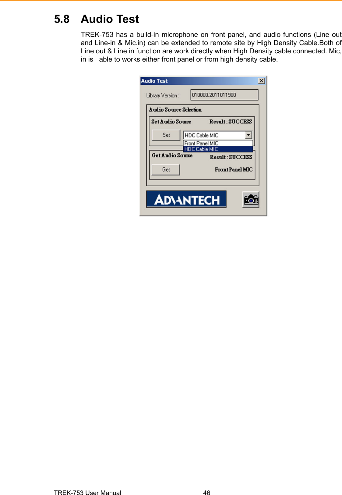
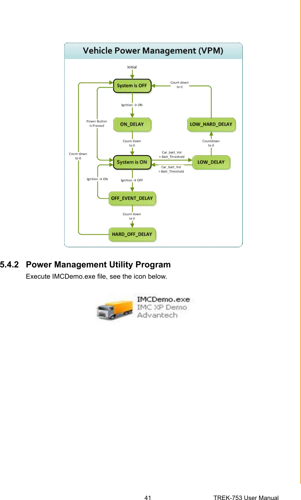
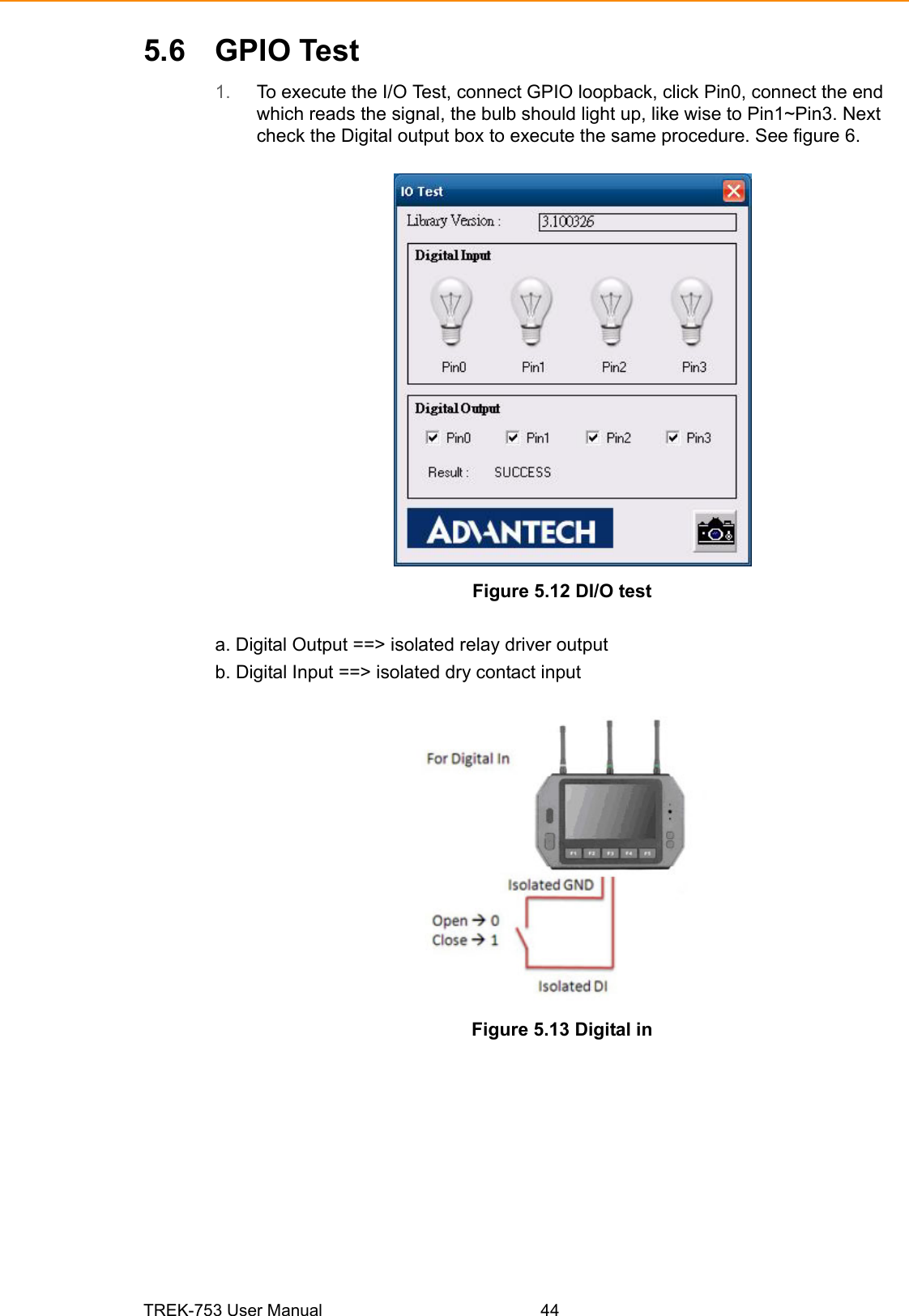
![TREK-753 User Manual 365.1 IntroductionTo make the hardware easier to access for programmers, Advantech has developeda demo utility in order to let customer test the functions on TREK-753. This documentdescribes detailed information for each Advantech demo utility so that applicationdevelopers can become more familiar with using them.For technical support, contact Advantech application engineers worldwide. For newsupdates, visit our website: www.advantech.com5.1.1 Execute J1939 Demo UtilityThis section explains how to install the Advantech demo utility in Windows XP Pro /Embedded.1. Execute the test program called “IMC_Demo”Figure 5.1 IMC demo utility2. Click J1939: customer may connect directly to the truck; we use a car simulator board below to explain how J1939 protocol can be executed. First, connect to the simulator board to TREK-753 CAN port and console PC, once the simulator is powered on (connect to the truck), you can start getting the data, just click [Read], you may get the data you need from the car simulator, click [Read], you may transfer the data to Console.](https://usermanual.wiki/Advantech-Co/TREK-753/User-Guide-1671861-Page-44.png)
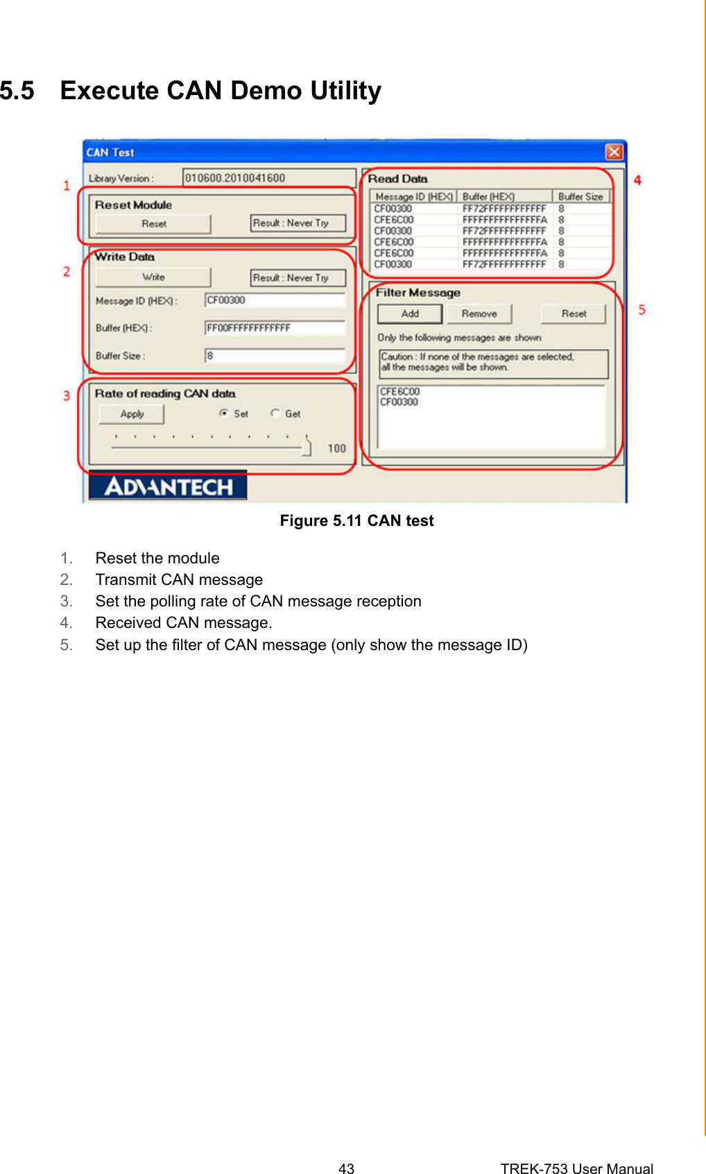
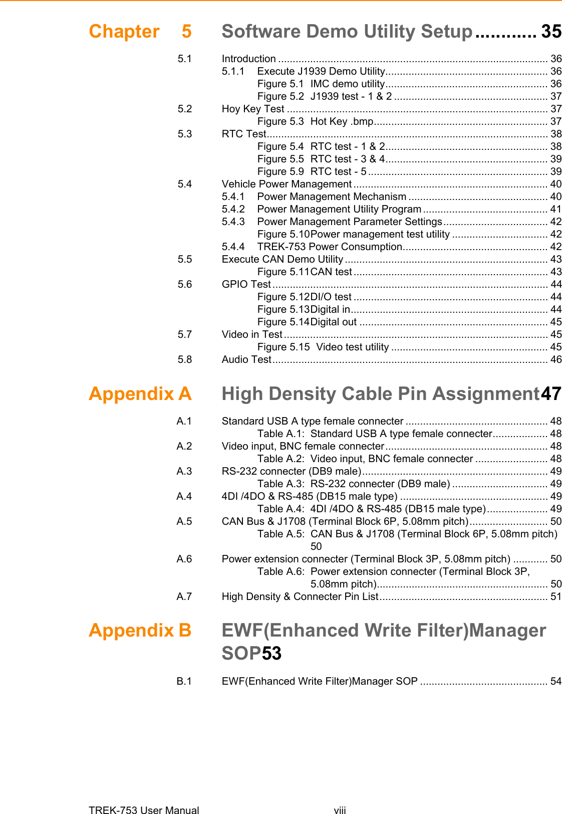
![45 TREK-753 User ManualChapter 5 Software Demo Utility SetupFigure 5.14 Digital out5.7 Video in TestThere are one video input, please connect camera to the port, CAM1. Choose Chan-nel 1 on [Switch to], then the panel will show the image which camera1 has taken,and it will recover to the same status after 10 sec. Figure 5.15 Video test utility](https://usermanual.wiki/Advantech-Co/TREK-753/User-Guide-1671861-Page-53.png)