Advantech Co TREK-753 Mobile Data Terminal User Manual V4 12 EV User Manual
Advantech Co Ltd Mobile Data Terminal V4 12 EV User Manual
User Manual

User Manual
TREK-753
Computer

TREK-753 User Manual ii
Copyright
The documentation and the software included with this product are copyrighted 2010
by Advantech Co., Ltd. All rights are reserved. Advantech Co., Ltd. reserves the right
to make improvements in the products described in this manual at any time without
notice. No part of this manual may be reproduced, copied, translated or transmitted
in any form or by any means without the prior written permission of Advantech Co.,
Ltd. Information provided in this manual is intended to be accurate and reliable. How-
ever, Advantech Co., Ltd. assumes no responsibility for its use, nor for any infringe-
ments of the rights of third parties, which may result from its use.
Acknowledgements
Intel and Atom are trademarks of Intel Corporation.
Microsoft Windows and MS-DOS are registered trademarks of Microsoft Corp.
All other product names or trademarks are properties of their respective owners.
Product Warranty (2 years)
Advantech warrants to you, the original purchaser, that each of its products will be
free from defects in materials and workmanship for two years from the date of pur-
chase.
This warranty does not apply to any products which have been repaired or altered by
persons other than repair personnel authorized by Advantech, or which have been
subject to misuse, abuse, accident or improper installation. Advantech assumes no
liability under the terms of this warranty as a consequence of such events.
Because of Advantech’s high quality-control standards and rigorous testing, most of
our customers never need to use our repair service. If an Advantech product is defec-
tive, it will be repaired or replaced at no charge during the warranty period. For out-
of-warranty repairs, you will be billed according to the cost of replacement materials,
service time and freight. Please consult your dealer for more details.
If you think you have a defective product, follow these steps:
1. Collect all the information about the problem encountered. (For example, CPU
speed, Advantech products used, other hardware and software used, etc.) Note
anything abnormal and list any onscreen messages you get when the problem
occurs.
2. Call your dealer and describe the problem. Please have your manual, product,
and any helpful information readily available.
3. If your product is diagnosed as defective, obtain an RMA (return merchandize
authorization) number from your dealer. This allows us to process your return
more quickly.
4. Carefully pack the defective product, a fully-completed Repair and Replacement
Order Card and a photocopy proof of purchase date (such as your sales receipt)
in a shippable container. A product returned without proof of the purchase date
is not eligible for warranty service.
5. Write the RMA number visibly on the outside of the package and ship it prepaid
to your dealer.
Part No. Edition 1
Printed in Taiwan August 2011

iii TREK-753 User Manual
Declaration of Conformity
CE
This product has passed the CE test for environmental specifications. Test conditions
for passing included the equipment being operated within an industrial enclosure. In
order to protect the product from being damaged by ESD (Electrostatic Discharge)
and EMI leakage, we strongly recommend the use of CE-compliant industrial enclo-
sure products.
FCC Class B
Note: This equipment has been tested and found to comply with the limits for a Class
B digital device, pursuant to part 15 of the FCC Rules. These limits are designed to
provide reasonable protection against harmful interference in a residential installa-
tion. This equipment generates, uses and can radiate radio frequency energy and, if
not installed and used in accordance with the instructions, may cause harmful inter-
ference to radio communications. However, there is no guarantee that interference
will not occur in a particular installation. If this equipment does cause harmful interfer-
ence to radio or television reception, which can be determined by turning the equip-
ment off and on, the user is encouraged to try to correct the interference by one or
more of the following measures:
Reorient or relocate the receiving antenna.
Increase the separation between the equipment and receiver.
Connect the equipment into an outlet on a circuit different from that to which the
receiver is connected.
Consult the dealer or an experienced radio/TV technician for help.
Technical Support and Assistance
1. Visit the Advantech web site at http://support.advantech.com where you can find
the latest information about the product.
2. Contact your distributor, sales representative, or Advantech's customer service
center for technical support if you need additional assistance. Please have the
following information ready before you call:
–Product name and serial number
–Description of your peripheral attachments
–Description of your software (operating system, version, application software,
etc.)
–A complete description of the problem
–The exact wording of any error messages

TREK-753 User Manual iv
Warnings, Cautions and Notes
Document Feedback
To assist us in making improvements to this manual, we would welcome comments
and constructive criticism. Please send all such - in writing to: support@advan-
tech.com
Packing List
Before setting up the system, check that the items listed below are included and in
good condition. If any item does not accord with the table, please contact your dealer
immediately.
TREK-753 series Computer
USB/LAN cable clip
Warranty card
Power cord: DC power inlet cable (200 cm - for TREK-753 only)
WWAN or WLAN Antennas (by options)
“Drivers, Utilities and User Manual" CD-ROM
End User License Agreement (WES and WinCE model), please download driver
and related document from http://support.advantech.com
Warning! Warnings indicate conditions, which if not observed, can cause personal
injury!
Caution! Cautions are included to help you avoid damaging hardware or losing
data. e.g.
There is a danger of a new battery exploding if it is incorrectly installed.
Do not attempt to recharge, force open, or heat the battery. Replace the
battery only with the same or equivalent type recommended by the man-
ufacturer. Discard used batteries according to the manufacturer's
instructions.
Note! Notes provide optional additional information.

v TREK-753 User Manual
Ordering Information
Safety Instructions
1. Read these safety instructions carefully.
2. Keep this User Manual for later reference.
3. Disconnect this equipment from any AC outlet before cleaning. Use a damp
cloth. Do not use liquid or spray detergents for cleaning.
4. For plug-in equipment, the power outlet socket must be located near the equip-
ment and must be easily accessible.
5. Keep this equipment away from humidity.
6. Put this equipment on a reliable surface during installation. Dropping it or letting
it fall may cause damage.
7. Do not leave this equipment in an environment unconditioned where the storage
temperature under -30° C (-22° F) or above 60° C (140° F), it may damage the
equipment.
8. Do not operate this equipment in an environment temperature may over 50° C
(122° F). The surface temperature of metal chassis may be scorch and hot.
9. Make sure the voltage of the power source is correct before connecting the
equipment to the power outlet.
10. Position the power cord so that people cannot step on it. Do not place anything
over the power cord.The voltage and current rating of the cord should be greater
than the voltage and current rating marked on the product.
11. All cautions and warnings on the equipment should be noted.
12. If the equipment is not used for a long time, disconnect it from the power source
to avoid damage by transient overvoltage.
13. Never open the equipment. For safety reasons, the equipment should be
opened only by qualified service personnel.
14. If one of the following situations arises, get the equipment checked by service
personnel:
The power cord or plug is damaged.
Liquid has penetrated into the equipment.
The equipment has been exposed to moisture.
The equipment does not work well, or you cannot get it to work according to
the user's manual.
The equipment has been dropped and damaged.
The equipment has obvious signs of breakage.
15. This device complies with Part 15 of the FCC rules. Operation is subject to the
following two conditions:
(1) this device may not cause harmful interference, and
Part Number Description
TREK-753R-0A0E TREK-753R Bare bone with Z510PT 1.1GHz CPU
TREK-753R-1A0E TREK-753R Bare bone with Z520PT 1.3GHz CPU
TREK-753S-0A0E TREK-753R Bare bone with 1.1G CPU/Sunlight readable touch
screen
TREK-753R-CWBXPA0E TREK-753R w/CDMA/GPS/WLAN/BT/1GB RAM/4G CF/WES
TREK-753R-HWBXPA0E TREK-753R w/HSDPA/GPS/WLAN/BT/1GB RAM/4G CF/WES
TREK-753R-GWBXPA0E TREK-753R w/GPRS/GPS/WLAN/BT/1GB RAM/4G CF/WES

TREK-753 User Manual vi
(2) this device must accept any interference received, including interference that
may cause undesired operation.
16. CAUTION: Always completely disconnect the power cord from your chassis
whenever you work with the hardware. Do not make connections while the
power is on. Sensitive electronic components can be damaged by sudden
power surges.
17. CAUTION: Always ground yourself to remove any static charge before touching
the motherboard, backplane, or add-on cards. Modern electronic devices are
very sensitive to static electric charges. As a safety precaution, use a grounding
wrist strap at all times. Place all electronic components on a static-dissipative
surface or in a static-shielded bag when they are not in the chassis.
18. CAUTION: Any unverified component could cause unexpected damage. To
ensure the correct installation, please always use the components (ex. screws)
provided with the accessory box.
Safety Precaution - Static Electricity
Follow these simple precautions to protect yourself from harm and the products from
damage.
To avoid electrical shock, always disconnect the power from your system chas-
sis before you work on it. Don't touch any components on the main board or
other cards while the system is on.
Disconnect power before making any configuration changes. The sudden rush
of power as you connect a jumper or install a card may damage sensitive elec-
tronic components.
Warning! 1. Input voltage rated: 6 ~ 36 Vdc (12/24V power) or 18 ~ 58 Vdc
(48V power, option).
2. Transport: carry the unit with both hands and handle with care.
3. Maintenance: to properly maintain and clean the surfaces, use only
approved products or clean with a dry applicator.
4. CF/SD/SIM card: Turn off the power before inserting or removing
CompactFlash storage cards.

vii TREK-753 User Manual
Contents
Chapter 1 General Information ............................1
1.1 Introduction ............................................................................................... 2
1.2 General Specifications .............................................................................. 3
1.3 Dimensions ............................................................................................... 5
Figure 1.1 TREK-753 dimensions................................................ 5
Chapter 2 System Setup.......................................7
2.1 A Quick Tour of the TREK-753 Computer ............................................. 8
Figure 2.1 Front view of TREK-753 ............................................. 8
Figure 2.2 Rear view of TREK-753.............................................. 8
Figure 2.3 Side view of TREK-753 .............................................. 9
Figure 2.4 Bottom view of TREK-753 .......................................... 9
2.2 Installation Procedures............................................................................ 10
2.2.1 Connecting the Power Cord........................................................ 10
Figure 2.5 Power connector photo............................................. 10
Table 2.1: Pin Definition of Power Cord .................................... 11
2.2.2 Power Connector ........................................................................ 11
Figure 2.6 Power connector outlook .......................................... 11
Table 2.2: Power Connector...................................................... 11
2.3 Running the BIOS Setup Program .......................................................... 12
2.4 Installing the Drivers for Win XP ............................................................. 12
Chapter 3 Hardware & Peripheral Installation ..13
3.1 Overview of Hardware Installation & Upgrading ..................................... 14
3.2 Installing the Storage Device and SIM Card ........................................... 14
3.3 Installing System Memory ....................................................................... 15
3.4 Installing Optional Accessories ............................................................... 15
3.5 Installing IO Cover................................................................................... 16
3.6 Installing Wireless options....................................................................... 19
3.6.1 WLAN.......................................................................................... 19
Figure 3.1 Top view of TREK-753 ............................................. 19
3.6.2 GPRS.......................................................................................... 22
Figure 3.2 Top view of TREK-753 ............................................. 22
3.6.3 HSDPA (3.5G) ............................................................................ 25
Figure 3.3 Top view of TREK-753 ............................................. 25
3.6.4 CDMA (3.5G) .............................................................................. 27
3.6.5 GPS ............................................................................................ 29
Figure 3.4 Bottom view of TREK-753 ........................................ 29
Chapter 4 Pin Assignments ...............................31
4.1 Rear Side Connectors............................................................................. 32
4.2 Power Connector .................................................................................... 32
Table 4.1: Power Connector...................................................... 32
4.3 High density Connector........................................................................... 33
Table 4.2: High Density Connector............................................ 33
4.4 RS-232 Connector (COM8)..................................................................... 34
Table 4.3: Table 5.5: RS-232 / RS-485 / J1708 Connector....... 34
4.5 LED Indicator .......................................................................................... 34

TREK-753 User Manual viii
Chapter 5 Software Demo Utility Setup............ 35
5.1 Introduction ............................................................................................. 36
5.1.1 Execute J1939 Demo Utility........................................................ 36
Figure 5.1 IMC demo utility........................................................ 36
Figure 5.2 J1939 test - 1 & 2 ..................................................... 37
5.2 Hoy Key Test .......................................................................................... 37
Figure 5.3 Hot Key .bmp............................................................ 37
5.3 RTC Test................................................................................................. 38
Figure 5.4 RTC test - 1 & 2........................................................ 38
Figure 5.5 RTC test - 3 & 4........................................................ 39
Figure 5.9 RTC test - 5 .............................................................. 39
5.4 Vehicle Power Management ................................................................... 40
5.4.1 Power Management Mechanism ................................................ 40
5.4.2 Power Management Utility Program ........................................... 41
5.4.3 Power Management Parameter Settings.................................... 42
Figure 5.10Power management test utility ................................. 42
5.4.4 TREK-753 Power Consumption.................................................. 42
5.5 Execute CAN Demo Utility ...................................................................... 43
Figure 5.11CAN test ................................................................... 43
5.6 GPIO Test ............................................................................................... 44
Figure 5.12DI/O test ................................................................... 44
Figure 5.13Digital in.................................................................... 44
Figure 5.14Digital out ................................................................. 45
5.7 Video in Test ........................................................................................... 45
Figure 5.15 Video test utility ...................................................... 45
5.8 Audio Test............................................................................................... 46
Appendix A High Density Cable Pin Assignment47
A.1 Standard USB A type female connecter ................................................. 48
Table A.1: Standard USB A type female connecter................... 48
A.2 Video input, BNC female connecter........................................................ 48
Table A.2: Video input, BNC female connecter ......................... 48
A.3 RS-232 connecter (DB9 male)................................................................ 49
Table A.3: RS-232 connecter (DB9 male) ................................. 49
A.4 4DI /4DO & RS-485 (DB15 male type) ................................................... 49
Table A.4: 4DI /4DO & RS-485 (DB15 male type)..................... 49
A.5 CAN Bus & J1708 (Terminal Block 6P, 5.08mm pitch)........................... 50
Table A.5: CAN Bus & J1708 (Terminal Block 6P, 5.08mm pitch)
50
A.6 Power extension connecter (Terminal Block 3P, 5.08mm pitch) ............ 50
Table A.6: Power extension connecter (Terminal Block 3P,
5.08mm pitch)........................................................... 50
A.7 High Density & Connecter Pin List.......................................................... 51
Appendix B EWF(Enhanced Write Filter)Manager
SOP53
B.1 EWF(Enhanced Write Filter)Manager SOP ............................................ 54

Chapter 1
1General Information
This chapter gives background
information on the TREK-753
Computer
.Sections include:
Introduction
General Specifications
Dimensions
TREK-753 User Manual 2
1.1 Introduction
Advantech-DLoG’s TREK-753 is a new generation, all-in-one Computer
with touchscreen. Its compact and rugged industrial design is perfect for in-vehicle
use where space, vibration, transient power, and temperature fluctuations will dam-
age most computer equipment. TREK-753 is the higher performing cousin of the
award-winning TREK-743 with its Intel® Atom™ Z510PT/US15 processor, increased
memory, the addition of an analog video input port, GbE LAN, and a rich complement
of I/O ports (additional COM ports, audio, CAN bus, and J1708). TREK-753 has also
been re-engineered to optimize internal space, gained by its full-flat panel touch-
screen; and it has moved the CF/SD/SIM card slot to make it externally accessible,
allowing easy access without having to open the unit.
TREK-753 is built tough. It has an EN 60721-3-5 certification, and meets military
standards for vibration and shock. This ruggedness allows TREK to boldly go where
others dare not, opening a wide range of vertical market applications. TREK-753 is
suitable for taxi and bus transport, in vehicle fleets of all types, in long-haul trucking,
and as an affordable solution to heavy duty vehicle applications. TREK-753 is
designed to operate flawlessly in transient power conditions. It supports 12/24 V
options, operating from 6 ~ 36 volts, and it is ISO7637-2 and SAEJ1113 compliant.
With power-on/power-off delay features which are software configurable, TREK holds
its own in unstable power conditions. And TREK can operate in the temperature
extremes found in vehicle environments.
I/O Connectors

3 TREK-753 User Manual
Chapter 1 General Information
1.2 General Specifications
Key features
7" WVGA LCD with 5 programmable adjustable brightness hot key
Support Windows Embedded System(W.E.S.) & WinCE6.0 & Linux Ubuntu
Analog video input, J1708 & CAN2.0b with J1939 protocol supported
Support CDMA/HSDPA/GPRS, GPS, WLAN, BT wireless communications
12V/24V option: 6~36V input range compliant to IOS7637-2 & SAE J1113
48V option: 18~58V input range for specific applications
Fan-less and ruggedized chassis with aluminum able to work under -30° C ~
60° C
IP54 rating with whole system protection in harsh environment under shock &
vibration (Passed EN60721-3-5 5M3 Shock/vibration 100G/4G test.)
Specifications
Dimensions: (W x H x D) - 255.7 x 161 x 56 mm (10.04" x 6.30"x2.20")
Weight: 2.2 kg (max.)
Vehicle power feature:
–Input voltage: 6 ~ 36 Vdc, support ignition cold crank
–Supports Ignition on/off
–Supports low battery shut-down protection threshold (optional)
–Supports power off event delay
–Supports power on delay
–Supports power low delay
–Supports power low hard delay
–Supports hard off delay
CPU/Chipset: Intel industrial Atom (eMenlow) 1.1GHz /1.33GHz (optional)
Chipset: On board Intel LE82US15EE
OS: Windows Embedded System(W.E.S.) & WinCE6.0 & Linux Ubuntu
RAM: One 200-pin SODIMM socket, Supports up to 2 GB DDR2 400/533
Storage:
–1 x SD card with external access (not for boot device)
–1 x external accessible type ll Compact Flash memory card only (boot device)
–1 x SIM card socket for GPRS/HSDPA
LCD: Display Type 7" 16:9 industrial degree TFT LCD, 800x480 resolution LED
backlight.
Touch screen: Type 4 wires Analog resistive type, continuous resolution,
optional to support sunlight readable TS
IO Function:
–1 x video input port for rear view monitor (Note: bypass video to screen, not
support video recording)
–1 x RS-232 COM port from rear IO; 1 x RS-232 COM port & 1x RS-485 port
from high density connecter.
–1 x USB 2.0 port from front panel; 1 x USB 2.0 port from rear IO; 1x USB 2.0
from high density connecter
–1 x 100/1000-T Gb LAN by RJ45 connecter
–1 x CAN 2.0B with J1939 protocol by High density connector
–1 x J1708 by High density connector
–1 x built-in 2.0w speaker & 1 x built-in microphone in front panel

TREK-753 User Manual 4
–1 x Line-in/Line-out/Mic.in I/F by High density connector or switch to high
density connector (by software)
–5 x green lighted, programmable function keys, 2 x for LCD brightness control
–1x light sensor on front cover for auto LCD brightness control
–4 x isolated DI & 4 x isolated DO
RF Function:
GPS:Built-in uBlox LEA-5S GPS module with external antenna in IO plate
Bluetooth: Built-in Class 2 Bluetooth V2.0 + EDR module
WWAN:
–GPRS module by Cinterion MC55i with SMA type antenna
–HSDPA module by Sierra wireless MC8790V with SMA type connector
–CDMA module by Sierra wireless MC5728V with SMA type connector
WLAN: Built-in 802.11b/g/n module with SMA type connector
Power Supply:
–Input Voltage 12V/24V option support 6~36V car power design with
ISO7637-2 & SAE J1113 compliant
–48v option support 18~58V input for specific application (Option)
Mechanical Design:
–Aluminum chassis with Optional to support whole system IP54 by extended
IO cover
–Weight- under 2.2 kg (~4.85 lbs)
–Dimensions (W x H x D) - 255.7 x 161 x 56 mm (10.04" x 6.30" x2.20")
Environmental Specifications:
–Operating Temperature : -30° C ~ 60° C
–Relative Humidity 95% @ 40° C (No condensing)
–Vibration & Shock: MIL-STD-810G (US highway truck), Method 516.5,
–SAE J1455, Class 5M3 according DIN EN 60721-3-5 (Lv.2 100G, 6ms,
shock)
5 TREK-753 User Manual
Chapter 1 General Information
1.3 Dimensions
Figure 1.1 TREK-753 dimensions
30 161
255.7
75
56
54 75 4-M5

TREK-753 User Manual 6

Chapter 2
2System Setup
This chapter details system setup
on TREK-753.
Sections include:
A Quick Tour of the Computer
Installation Procedures
Running the BIOS Setup Pro-
gram
Installing the Drivers for Win XP

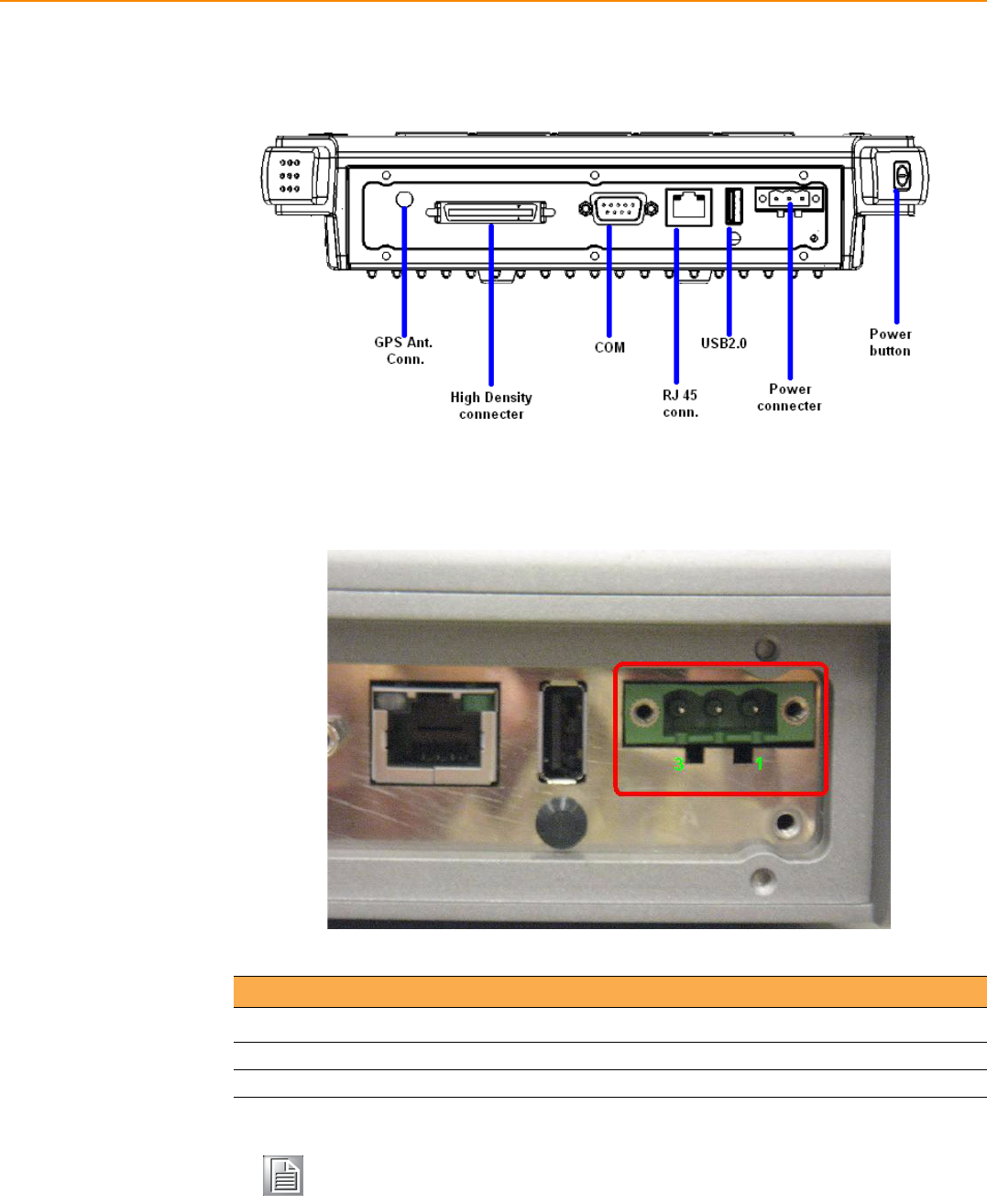
TREK-753 User Manual 8
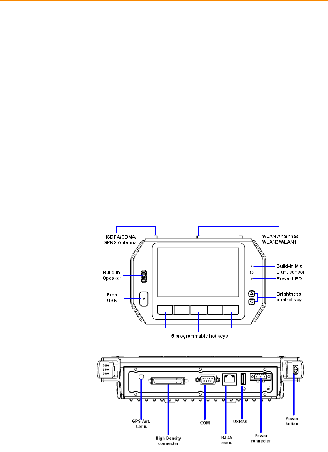
2.1 A Quick Tour of the TREK-753 Computer
Before starting to set up the Computer , take a moment to become familiar
with the locations and functions of the controls, drives, connectors and ports, which
are illustrated in the figures below. When the computer is placed inside
truck glove cabinet or under the passenger’s seat next to the driver, its front appears
as shown in Figure 2.1.
Figure 2.1 Front view of TREK-753
Figure 2.2 Rear view of TREK-753
9 TREK-753 User Manual
Chapter 2 System Setup
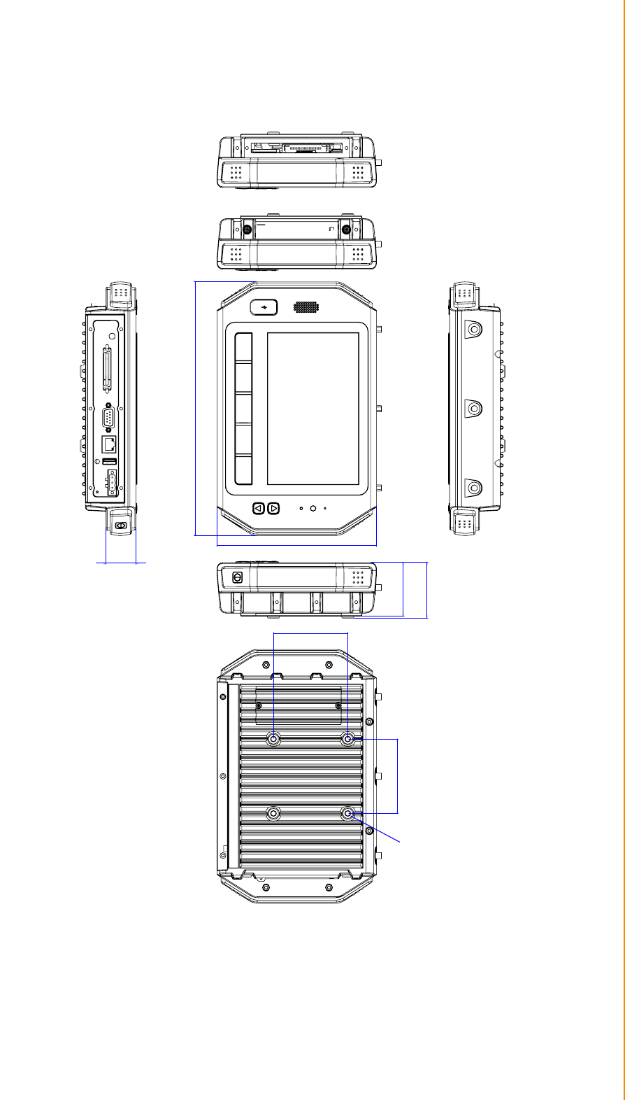
Figure 2.3 Side view of TREK-753
Figure 2.4 Bottom view of TREK-753
TREK-753 User Manual 10
2.2 Installation Procedures
When you installing TREK-753, the first step will be connect the car power and igni-
tion correctly. TREK-753 power cable is designed to connect car battery directly.
TREK-753 can be switched ON/OFF by the car ignition signal or its power button
both.
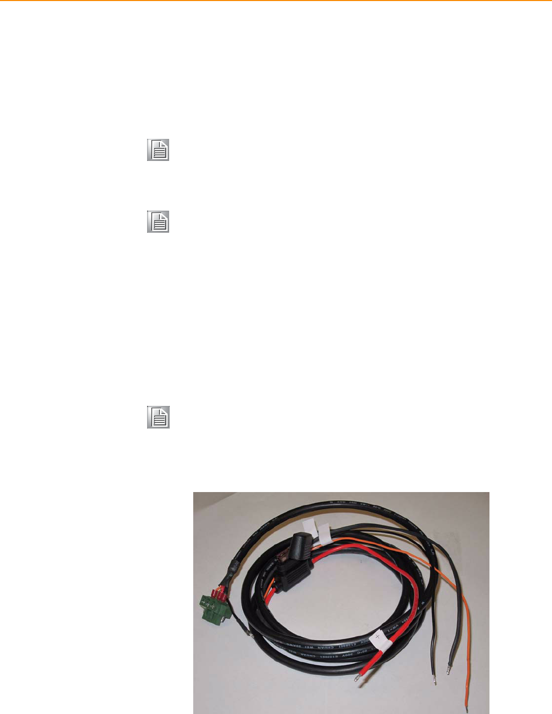
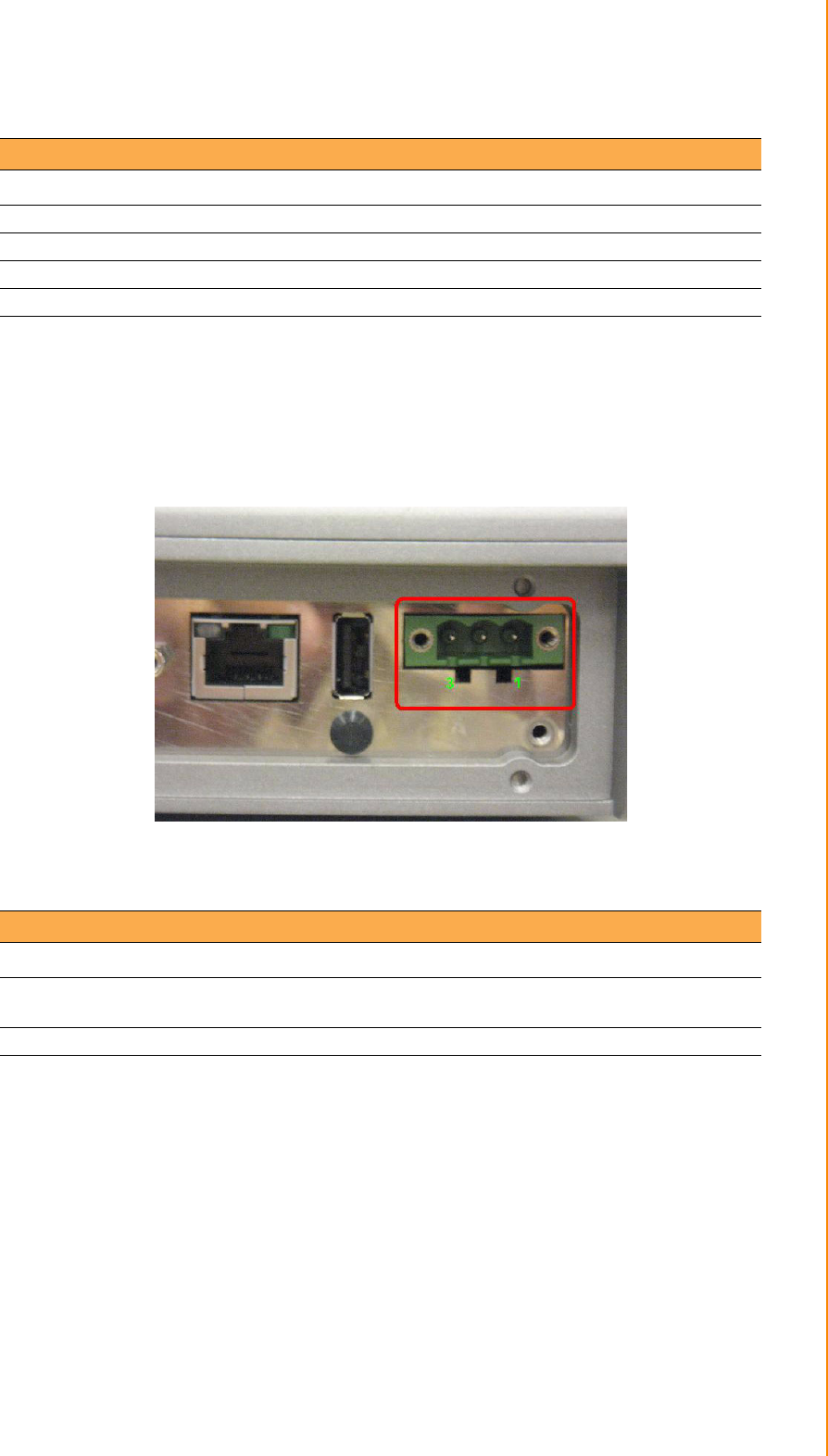
2.2.1 Connecting the Power Cord
Connect the three pin waterproof power cord to the DC inlet of TREK-753. On the
open-wire end, one pin is reserved for positive voltage and is marked "+" which
needs to be connected to the car power "+" side; one pin is reserved for ground and
is marked "-"; which needs to be connected to the car power "-" side. And, one pin is
reserved for the ignition signal with an “ignition” mark. There's independent "Shield"
pin in power cable, please fixed its O-ring which besides of power connecter of
TREK-753.
Connector : DECA Switchlab ME050-50803
Mating connector: MC101-50803-3Y
Figure 2.5 Power connector photo
Note! TREK-753 power input support 12V/24V & 48V DC input. The default
setting is for 12V or 48V (option board) only. If customer needs 24V DC
input, please contact regional sales or distributors to customized in
advance.
Note! The Fuse for 12V/24V (10A) system and for 48V (5A) in power cable are
different. Please check the fuse in your power cable before system
power on.
Note! Ignition on/off setting: The TREK-753 supports an ignition on/off function
so that you can power on/off the TREK-753 via the ignition signal/volt-
age and connect the TREK-753 vehicle ignition switch.
11 TREK-753 User Manual
Chapter 2 System Setup
2.2.2 Power Connector
TREK-753 can be powered on/off by power button or Acc ignition directly. Ignition on/
off will have 5sec (default) delay when power on/off. It can avoid the floating car
power supply impact or damage system operation. For more detail of power manage-
ment, please see Power mangement in Chapter 5.
Figure 2.6 Power connector outlook
Table 2.1: Pin Definition of Power Cord
Pin Definition Color
1+Red
2 Shield Black
3- Black
4 Ignition Orange
Table 2.2: Power Connector
Pin Signal Pin Signal
1Ground 2 Power input
(6~36VDC;18~58VDC)
3 Acc Ignition Input

TREK-753 User Manual 12
2.3 Running the BIOS Setup Program
In most cases, the computer will have been properly set up and configured by the
dealer or SI prior to delivery. However, it may still be necessary to adjust some of the
computer's BIOS (Basic Input-Output System) setup programs to change the system
configuration data, like the current date and time, or the specific type of hard drive
currently installed.
The setup program is stored in read-only memory (ROM). It can be accessed either
when turning on or resetting the computer, by pressing the “Del” key on the keyboard
immediately after powering up the computer.
The settings that are specified with the setup program are recorded in a special area
of the memory called CMOS RAM. This memory is backed up by a battery so that it
will not be erased when turning off or resetting the system. Whenever the power is
turned on, the system reads the settings stored in CMOS RAM and compares them
to the equipment check conducted during the power on self-test (POST). If an error
occurs, an error message is displayed on screen, and the user is prompted to run the
setup program.
2.4 Installing the Drivers for Win XP
After installing system software, the computer is ready to set up the Intel® chipset,
VGA, audio, LAN, and touch screen functions. All the pre-requisite drivers are stored
on a CD-ROM disc entitled “Drivers and Utilities” (Check the correct wording on the
CD, which can be found in the accessory box.)
The utility directory includes multimedia programs. Some drivers and utilities in the
CD-ROM disc have their own text files which help users install the drivers and under-
stand their functions.
These files are a very useful supplement to the information in this manual. For more
updated driver please refers to Advantech website, www.advantech.com/support
The drivers for TREK-753 are listed as below, please just execute the drivers for
installation.
Device Version
Intel SCH INF Update 8.8.0.1011
Intel US15 GMA500 Graphic Driver 6.14.11.1018
PenMount Universal Driver 2.1.1.0
Realtek RTL8111DL 10/100/1000 PCI-E NIC 5.728.604.2009
Realtek ALC892 High Definition Audio 5.10.0.5804
FTDI FT4232 BUS USB Driver 2.6.0.0
ublox LEA-5S Driver 1.2.0.5
Sierra Wireless MC5728V 5.1.2535.0
Sierra Wireless MC8790V 6.20.0.7
Ralink RT3091 Wireless LAN Card (AW-NE768) 1.4.2.1
BT-203B Utility BlueSoleil (Optional) 2.1.3.0
Note! The drivers and utilities used for the TREK-753 are subject to change
without notice. If you are in doubt, check Advantech's website or contact
our application engineers for the latest information regarding drivers and
utilities.

Chapter 3
3Hardware & Peripheral
Installation
This chapter details the installa-
tion of hardware for TREK-753.
Sections include:
Overview of Hardware Installa-
tion and Upgrading
Installing the Storage Device
and SIM Card
Installing System Memory
Installing the Drivers for Win XP
TREK-753 User Manual 14
3.1 Overview of Hardware Installation & Upgrading
The computer consists of a industrial computer that is housed in a rugge-
dized aluminum enclosure. Any memory module or storage maintenance or hard-
ware upgrades can be completed after removing the rear side RAM door/ Side cover,
or remove the front panel to install.
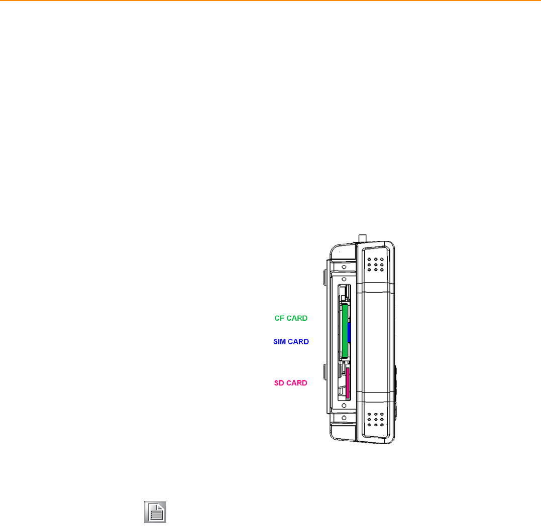
3.2 Installing the Storage Device and SIM Card
TREK-753 has a side door and user can install SIM card and storages (CF or SD
card) easily. CF card is the main bootable storage which has OS pre-installed from
Advantech. CF slot with a ejector (on the top side) then you can press and CF
ejected from socket. SD card as a secondary storage in TREK-753, system is NOT
allowed boot up from SD.
Note! Please do NOT paste any sticker or label on CF and SD , it might be
jammed and not able to ejected from slot/socket.
15 TREK-753 User Manual
Chapter 3 Hardware & Peripheral Installation
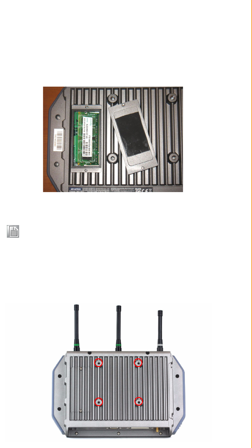
3.3 Installing System Memory
TREK-753 support 200-pin SO DIMM type DDRII DRAM. There's a door can be open
for RAM installation.It is very easy to open to install memory. But, we suggest this
change performed by our service center to avoid any possible damage (like ESD or
wrong position inserted).
3.4 Installing Optional Accessories
Optional accessories, like RAM mount kits or other functional modules are available
for purchase to complement TREK-753. All of standard 75mm type mounting with M5
type screws only.
Note! For system thermal design, please make sure the thermal pad on RAM
door (Block in black) is always needs to be assembled before the door
re-covered.(To bare bone system ,thermal pad will be placed in the
accessory box).
TREK-753 User Manual 16
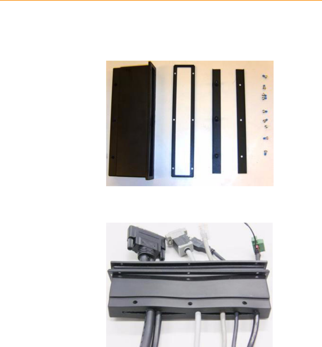
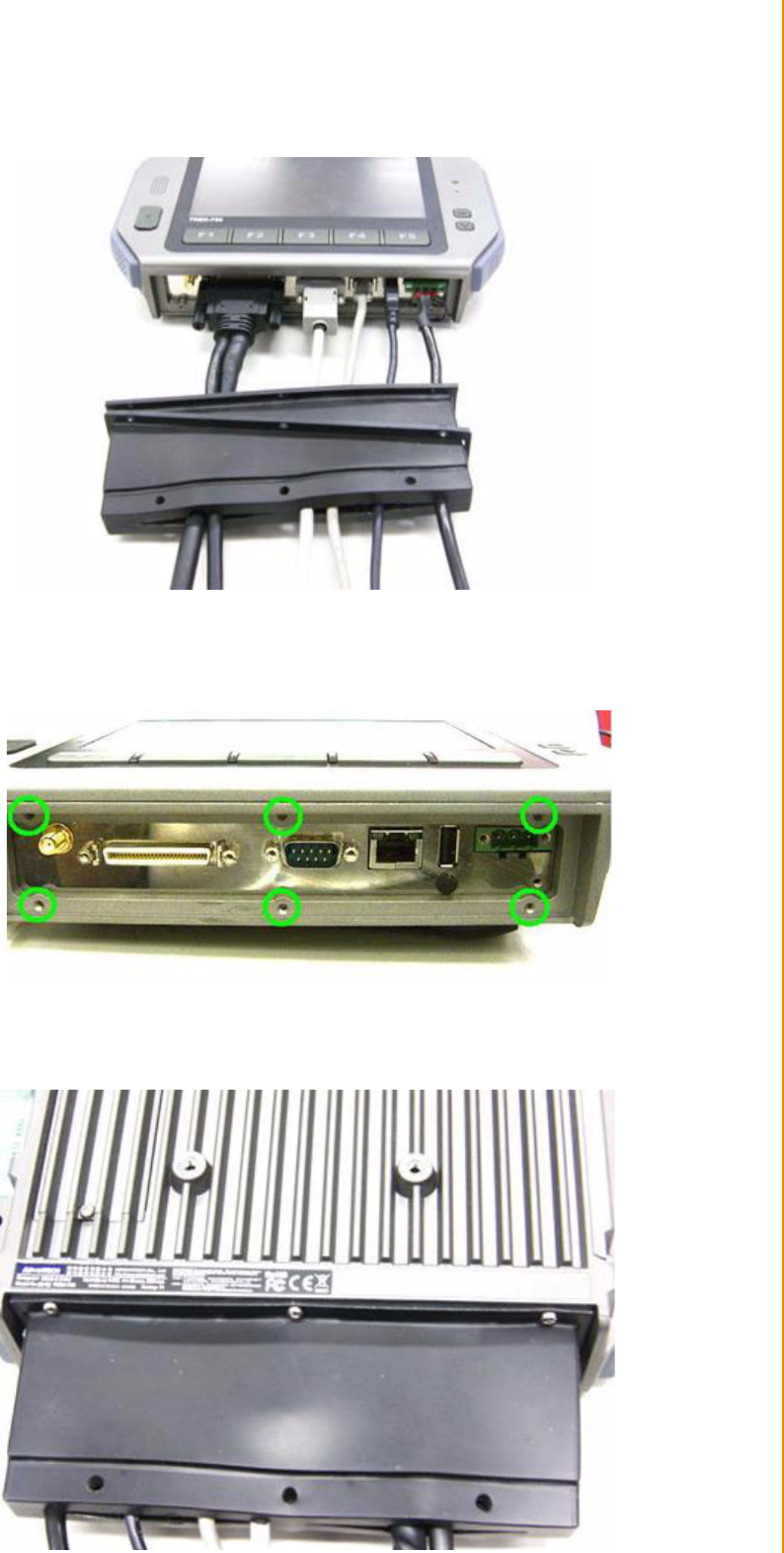
3.5 Installing IO Cover
For TREK-753 whole system IP54 ability, here is a IP54 IO cover kit to mask all the
connecters of bottom side. It's a rubber-metal kit includes a rubber cover, a screws
mounting frame, batten & batten with boss.
From left to right: Rubber cover; mounting frame, batten with boss & batten, screws.
Put the frame on the rubber cover, and lead all cables across the cover out side in.
17 TREK-753 User Manual
Chapter 3 Hardware & Peripheral Installation
Connect all cables to system and fix in tie before the cover installed.
There're 6 screws holes designed for extra mechanic part installation. The mounting
frame needs to be fixed with these holes.
Install the cover by 6 screws installed. It will be easy to install rear side first (3
screws) first.
TREK-753 User Manual 18
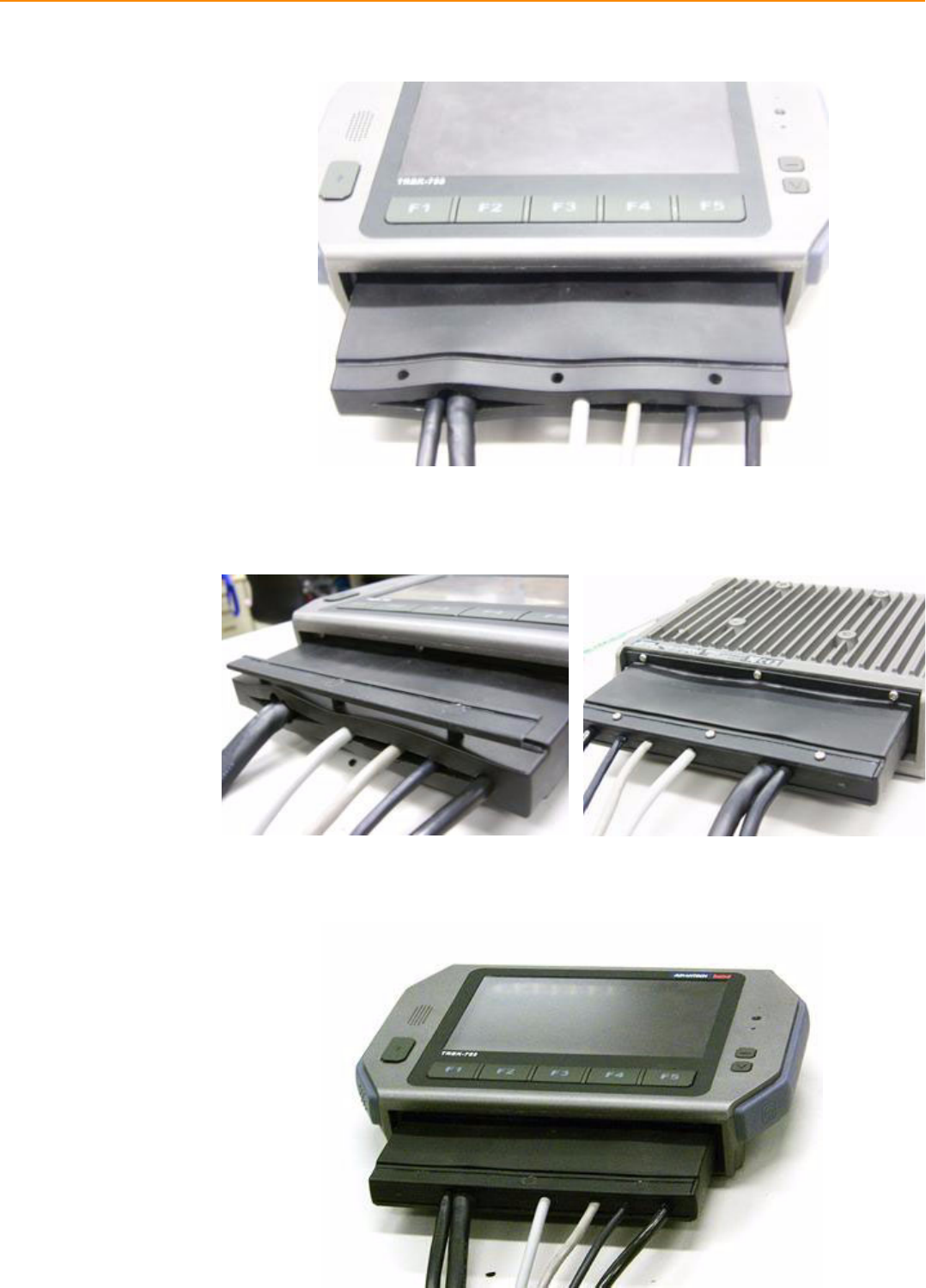
Then install frame with other 3 screws at top side.
Insert the batten with boss to the rubber cover. Please place all cables in the right
position before another batten fixed in tight.
Installation complete.
19 TREK-753 User Manual
Chapter 3 Hardware & Peripheral Installation
3.6 Installing Wireless options
TREK-753 is a highly integrated all-in-one terminal, all wireless options are able to
installed at once and works by independent connection. In the standard OS compan-
ioned with TREK-753, all the wireless connections have been setup in advance and
users will not have to setup again. These information provided for those who needs
to build new wireless connections if necessary. RF options include:
Bluetooth
Wireless LAN(WLAN)
WWAN (GPRS/CDMA/HSDPA)
GPS
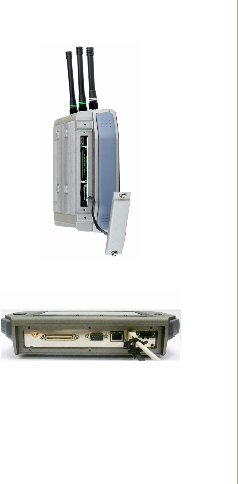
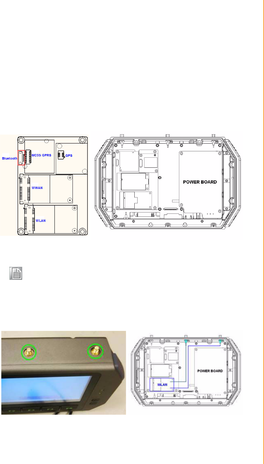
3.6.1 WLAN
Driver installation
1. Make sure the Wi-Fi module has install to the TREK-753.
Figure 3.1 Top view of TREK-753
Note! All of hardware or reconfiguration changes should be performed by ser-
vice center or authorized institutions of ADVANTECH.

TREK-753 User Manual 20
2. Make sure there is/are wireless router/AP working in same circumstance which
TREK-753 is able to connect with.
3. Turn on the TREK-753, booting into OS.
4. Double click the "Setup.exe" in driver CD (WLAN_AW-NE768_090714) to install
driver
Setup connection
1. Press Start - Control panel - Network connections - Press right button of mouse
and select properties in Wireless Network connection, then click "View Available
Wireless Networks".
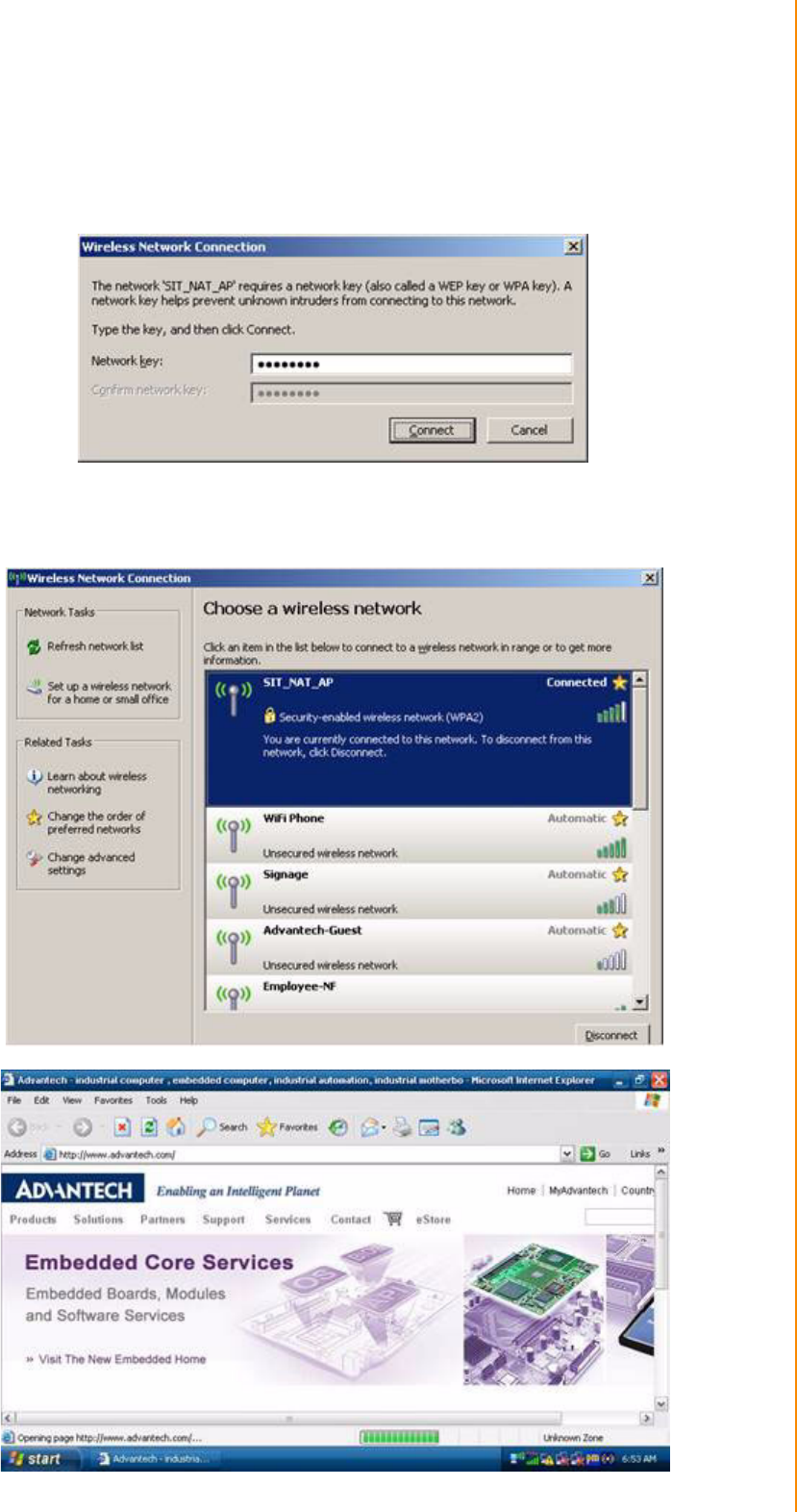
21 TREK-753 User Manual
Chapter 3 Hardware & Peripheral Installation
2. Double click the available wireless LAN icon on the down-right corner and
search for AP devices.
3. There might have some APs devices appear with different SSID, choice the
available one and connect with (might need to input user's ID & password)
4. Click "Connect" to connect with wireless AP. Open the web browser and TREK-
753 will connect to internet.
TREK-753 User Manual 22
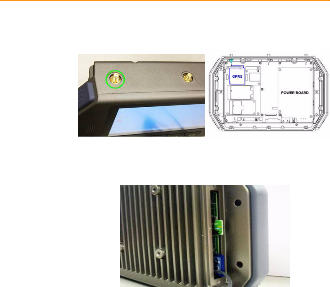
3.6.2 GPRS
Driver installation
1. Make sure the Criterion MC55i GPRS module has install to the TREK-753.
Figure 3.2 Top view of TREK-753
2. Insert the User's SIM card to slot of TREK-753, make sure the User's SIM card
has applied the GSM and data transmit/receive service in advance.
3. Turn on the TREK-753, booting into OS.
4. GPRS(MC55i) connected with system by COM port interface, it don't have to
install driver. But, please check the device manager without any question mark
in advance.

23 TREK-753 User Manual
Chapter 3 Hardware & Peripheral Installation
Setup connection
1. Press Start - Control Panel - Phone and Modem options.
2. Switch to Dialing rules tab, press button "New", input GPRS to the Location
name, input "00" to Area code.
3. Switch to Modems tab, press button "Add", select the "Don't detect my modem;
select it from a list" - Next.
4. Choose "Standard 19200 bps Modem" - Next.
5. Select COM port - Next - Finish, the screen will display the "standard 19200 bps
Modem" item.
6. Press button "Properties", switch to Modem tap and select "Maximum Port
Speed" change speed from 19200 to 115200 - press ok.
7. Switch to advanced tap, in extra setting textbox, input:at+cgdcont=1,"IP","inter-
net" - press ok.
8. In the Network Connections Panel, Select Make New Connection.
9. In the Make New Connection Dialogue, choose "Connect to the Internet" , then
click next.
10. Choose "Set up my connection manually", then click next.
11. Choose "Connect using a dial up modem", then click next.
12. Input ISP Name (ex: GPRS) then click next.
13. Do NOT input Phone number, User name and Password.
14. In completing the new connection wizard textbox, select "Add a shortcut to this
connection to my desktop", then click Finish.
15. In the Network Connections Panel, press right button of mouse then select
properties.
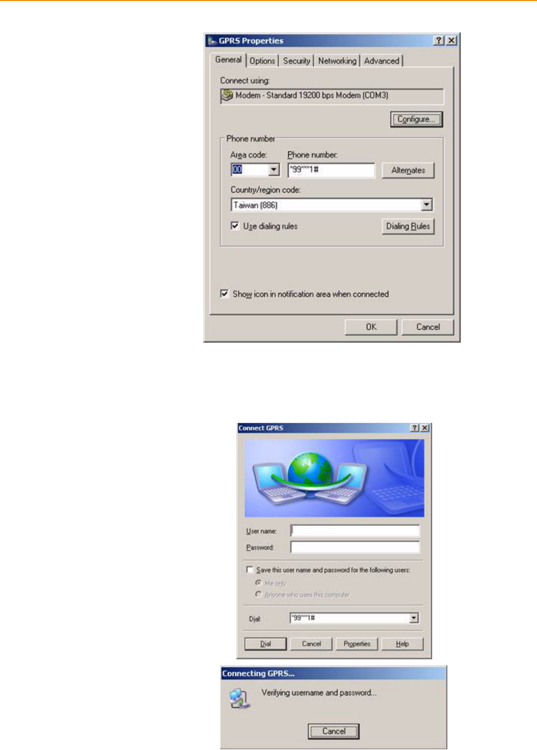
16. In the "Phone number textbox, input:*99***1#, then click Configure.
TREK-753 User Manual 24
17. Change "Maximum speed (bps) to 115200,then click OK.
18. Once complete previous steps, the new connection will be created.
19. Double Click the new connection and Click Button "Dial", then the TREK-753
will connect to the internet.
25 TREK-753 User Manual
Chapter 3 Hardware & Peripheral Installation
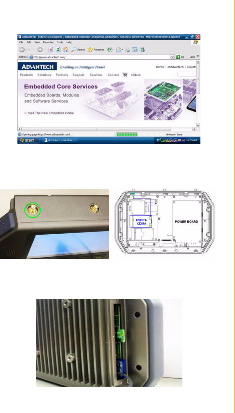
3.6.3 HSDPA (3.5G)
Driver installation
1. Make sure the HSDPA module has install to the TREK-753.
Figure 3.3 Top view of TREK-753
2. Insert the User's SIM card to slot, make sure the User's SIM card has applied
the 3G service.
TREK-753 User Manual 26
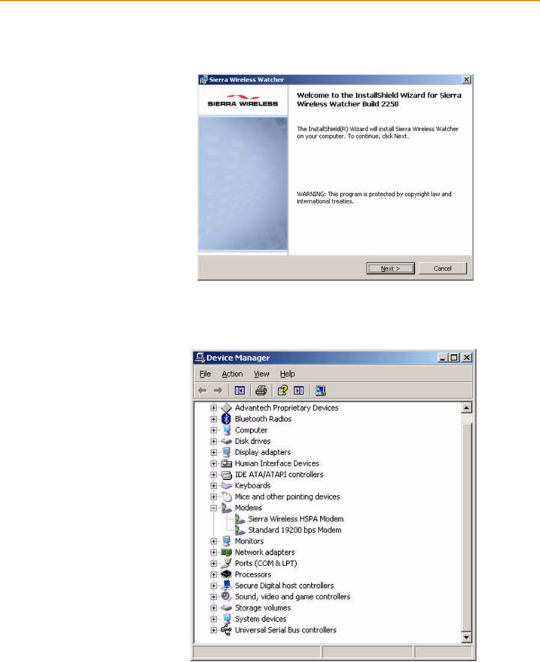
3. Turn on the TREK-753, then booting into OS.
4. Install the HSDPA USB module driver/AP "Watcher_Generic Build 2258.msi"
from driver CD into the Windows Embedded OS.
Setup connection
1. Check the device manager without any question mark.
2. In completing the new connection wizard textbox, select "Add a shortcut to this
connection to my desktop", then click Finish.
3. Once complete previous steps, the new connection will be created.
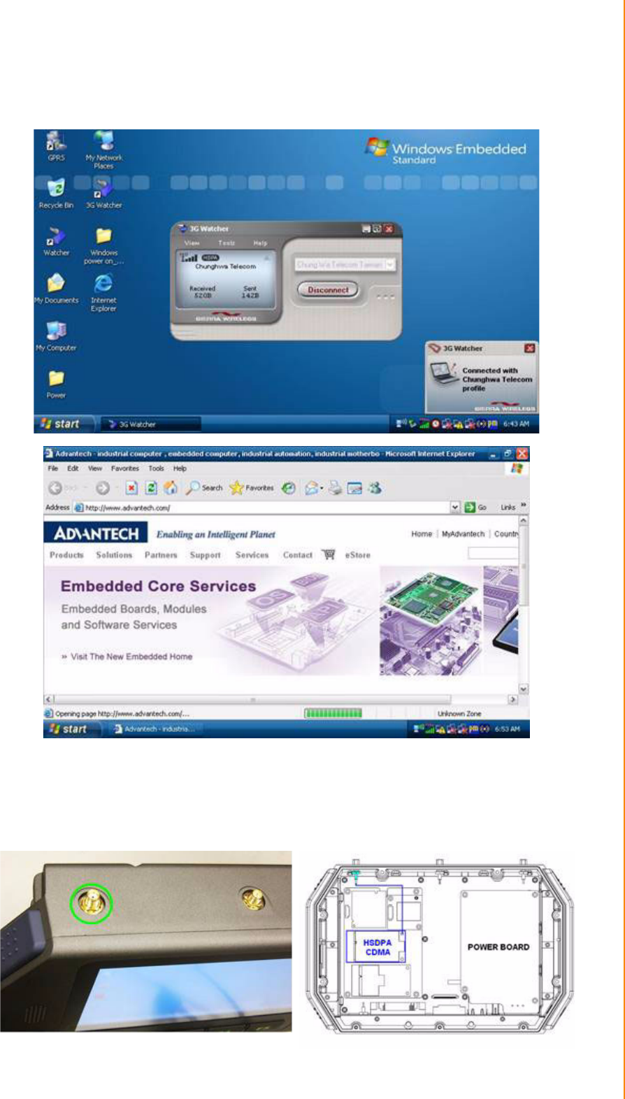
27 TREK-753 User Manual
Chapter 3 Hardware & Peripheral Installation
4. Double Click the "Sierra Wireless Watcher" and Click Button "Connect", then the
TREK-753 will connect to the internet.
3.6.4 CDMA (3.5G)
Driver installation
1. Make sure the CDMA module has install to the TREK-753.
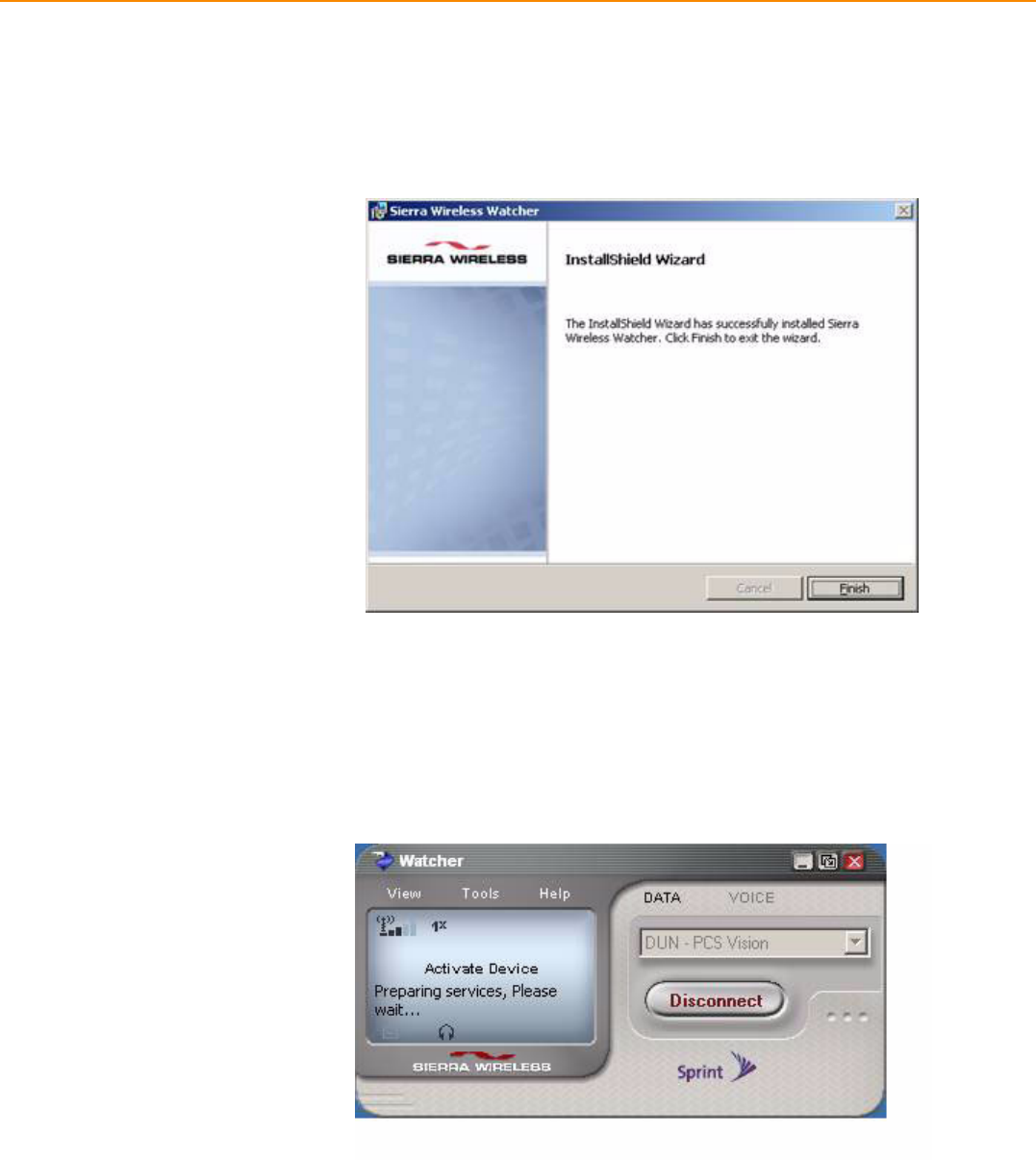
TREK-753 User Manual 28
2. Insert the User's SIM card to slot, make sure the User's SIM card has applied
the 3G service.
3. Turn on the TREK-753, then booting into OS.
4. Install the CDMA USB module driver "Watcher 7.11.msi" into the Windows
Embedded OS.
Setup connection
1. In completing the new connection wizard textbox, select "Add a shortcut to this
connection to my desktop", then click Finish.
2. Once complete previous steps, the new connection will be created.
3. Double Click the on desktop and Click Button "Connect", then the TREK-753 will
connect to the internet.
29 TREK-753 User Manual
Chapter 3 Hardware & Peripheral Installation
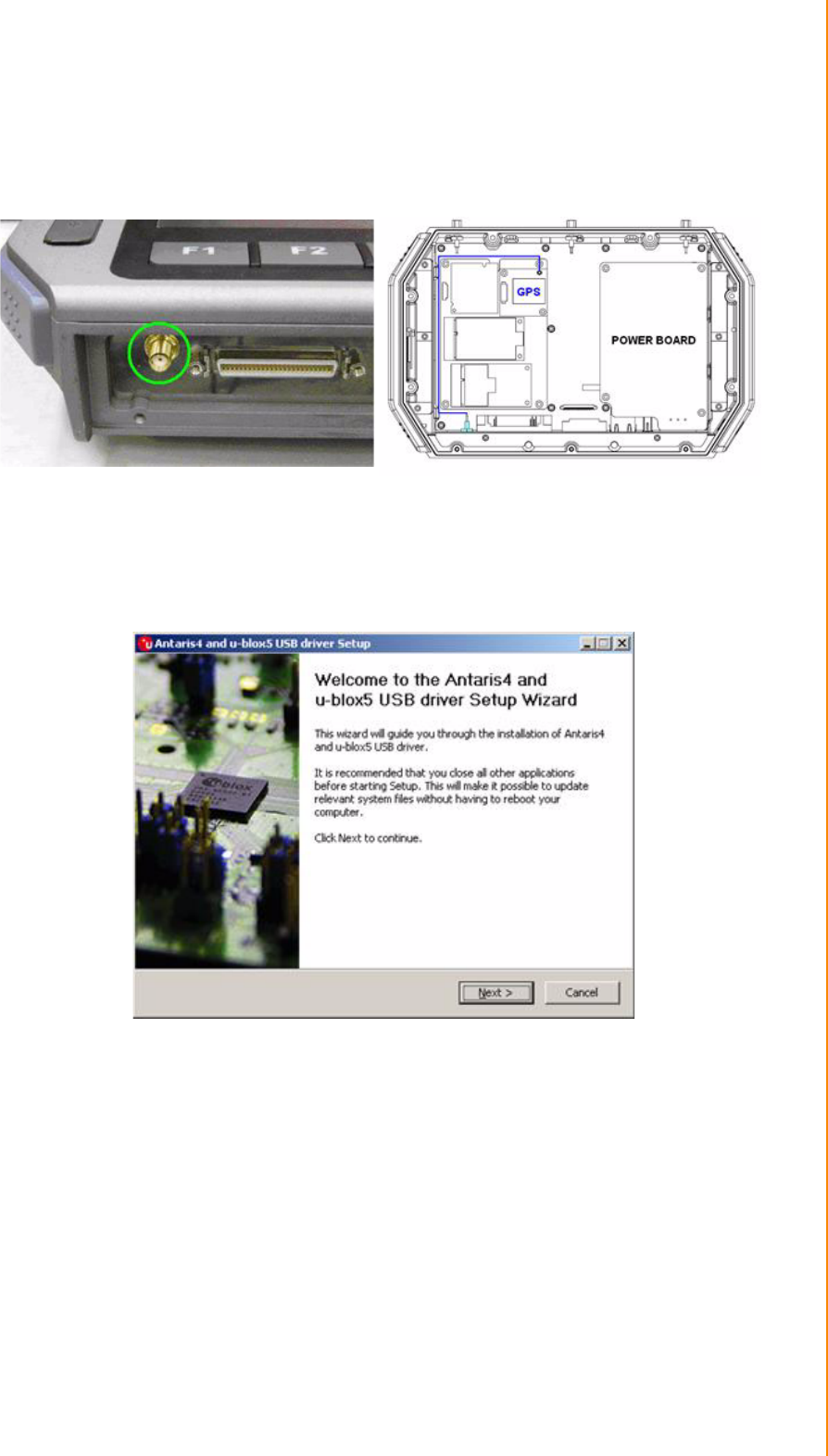
3.6.5 GPS
Installation
1. Make sure the GPS module & antenna has install to the TREK-753.
Figure 3.4 Bottom view of TREK-753
2. Turn on the TREK-753, booting into OS.
3. Double click the "ublox_A4_U5_USB_drv3264_install_UI.exe" application pro-
gram in driver CD and install to TREK-753 OS.
TREK-753 User Manual 30
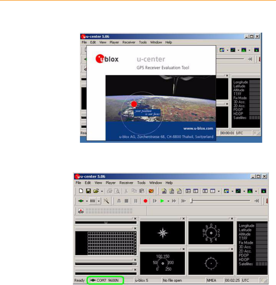
Setup connection
1. Install the "u-Center" for setup and test.
2. Start test in "u-Center", setting COM port (COM7) and baud rate (9600bps) use
for GPS module.
3. After start test, the NMEA output messages are display on the Development
Data View setup connection.

Chapter 4
4Pin Assignments
This chapter explains pin assign-
ments on the TREK-753.
TREK-753 User Manual 32
4.1 Rear Side Connectors
4.2 Power Connector
Table 4.1: Power Connector
Pin Signal Pin Signal
1 Ground 2 Power input
3 Acc Ignition Input
Note! TREK-753 has 2 power options for different vehicle:
Input Voltage 12 V/24 V option support 6~36 V car power design
with ISO7637-2 & SAE J1113 compliant (default)
48 V option support 18~58 V input for specific application (Option)

33 TREK-753 User Manual
Chapter 4 Pin Assignments
4.3 High density Connector
Table 4.2: High Density Connector
Pin Signal Pin Signal
1 +5VDC output (+/- 5%, max 0.5A) 2 +5VDC output (+/- 5%, max 0.5A)
3 USB Ground 4 USB D+
5USB D- 6 CVBS Ground
7CVBS IN 8 RSVD
9Audio Ground 10 LINE OUT L
11 LINE OUT R 12 LINE IN R
13 LINE IN L 14 MIC IN
15 RS-485 Ground 16 COM5 485-
17 COM5 485+ 18 J1708 Ground
19 COM6 J1708- 20 COM6 J1708+
21 Isolation CAN Ground 22 CAN L
23 CAN H 24 RSVD.
25 RSVD. 26 +12VDC output
27 +12VDC output 28 +12VDC output
29 Power Ground 30 Power Ground
31 Power Ground 32 COM9 RS232 RI#
33 COM9 RS232 CTS# 34 COM9 RS232 RTS#
35 COM9 RS232 DSR# 36 RS232 Ground
37 COM9 RS232 DTR# 38 COM9 RS232 TXD
39 COM9 RS232 RXD 40 COM9 RS232 DCD#
41 RSVD. 42 Isolated Relay Driver Output 4#
43 Isolated Relay Driver Output 3# 44 Isolated Relay Driver Output 2#
45 Isolated Relay Driver Output 1# 46 Isolated Dry Contact Input 4
47 Isolated Dry Contact Input 3 48 Isolated Dry Contact Input 2
49 Isolated Dry Contact Input 1 50 Isolation DIO Ground
TREK-753 User Manual 34
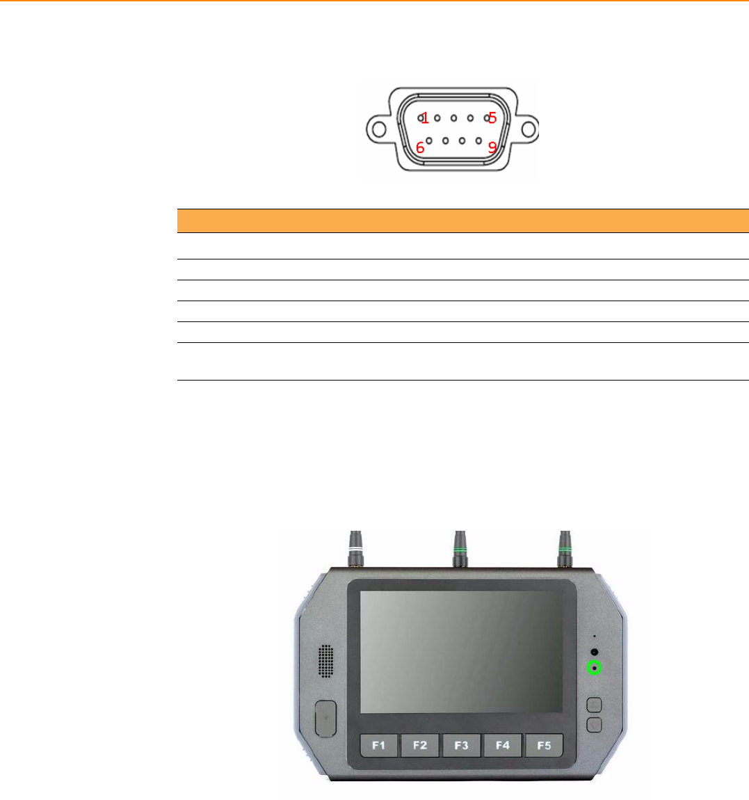
4.4 RS-232 Connector (COM8)
4.5 LED Indicator
This system power indicator is an orange LED,controlled by hadrware.
This LED will be lit on when the system is in NORMAL mode.
When system is off, this LED will be lit off.
Table 4.3: Table 5.5: RS-232 / RS-485 / J1708 Connector
Pin Signal Pin Signal
1 RS-232 DCD 2 RS-232 RXD
3 RS-232 TXD 4 RS-232 DTR
5 RS-232 Ground 6 RS-232 DSR
7 RS-232 RTS 8 RS-232 CTS
9RS-232 RI / +12 VDC (max. 2500
mA)

Chapter 5
5Software Demo Utility
Setup
This appendix explains the soft-
ware demo utility for TREK-753.
Sections include:
Introduction
How to Set up Demo Utility
Installing the Drivers for Win XP
TREK-753 User Manual 36
5.1 Introduction
To make the hardware easier to access for programmers, Advantech has developed
a demo utility in order to let customer test the functions on TREK-753. This document
describes detailed information for each Advantech demo utility so that application
developers can become more familiar with using them.
For technical support, contact Advantech application engineers worldwide. For news
updates, visit our website: www.advantech.com
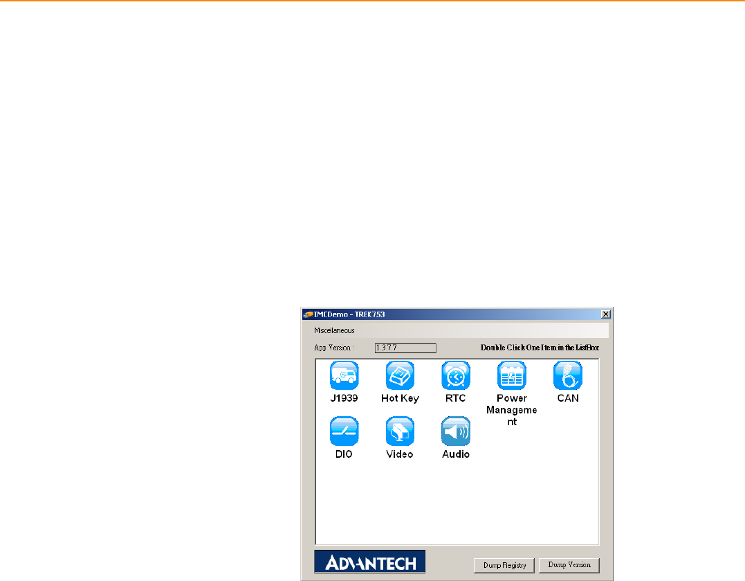
5.1.1 Execute J1939 Demo Utility
This section explains how to install the Advantech demo utility in Windows XP Pro /
Embedded.
1. Execute the test program called “IMC_Demo”
Figure 5.1 IMC demo utility
2. Click J1939: customer may connect directly to the truck; we use a car simulator
board below to explain how J1939 protocol can be executed.
First, connect to the simulator board to TREK-753 CAN port and console PC,
once the simulator is powered on (connect to the truck), you can start getting the
data, just click [Read], you may get the data you need from the car simulator,
click [Read], you may transfer the data to Console.
37 TREK-753 User Manual
Chapter 5 Software Demo Utility Setup
Figure 5.2 J1939 test - 1 & 2
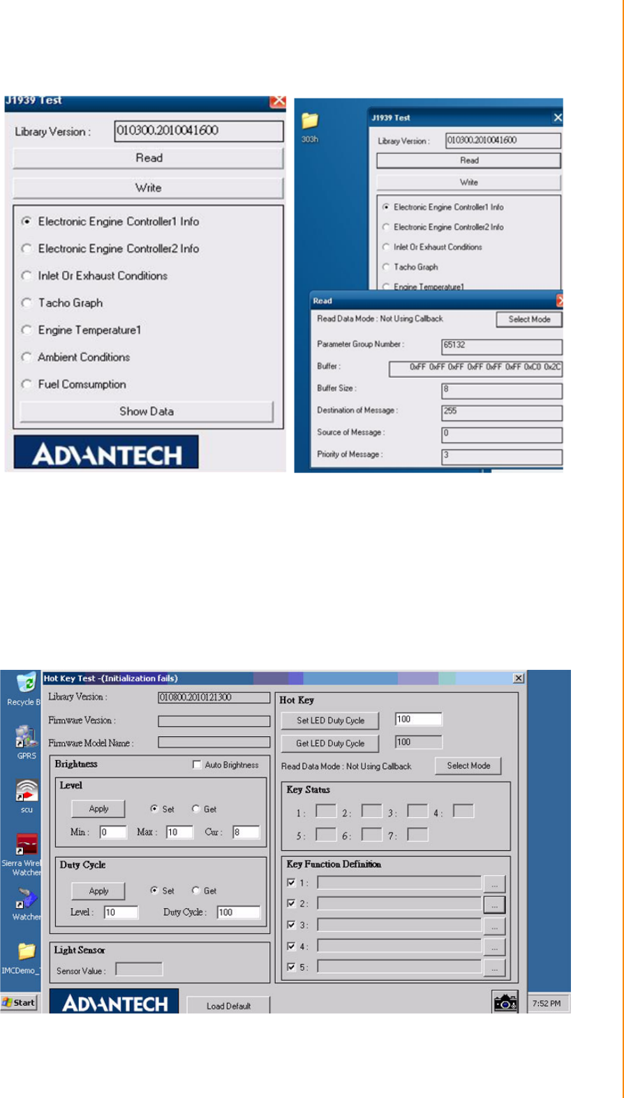
5.2 Hoy Key Test
Click "Hot Key test" program in IMC demo main menu.
If check "Auto Brightness"; TREK-753 will adjust the panel brightness automatically
by build in Light sensor input. Or user can set the brightness of panel and hot key
manually.
Figure 5.3 Hot Key .bmp
TREK-753 User Manual 38
Brightness level: Check "Set" option then key in brightness from level 0 ~10 in "Cur"
column.
The number bigger, the panel is brighter.
When you finish setting the brightness level you want, please click "Apply".
If you want to check the current brightness level, please click "Get".
Duty cycle: You may set every level's brightness strength, to every levels,
After you finish setting the "Level" and "Duty Cycle" vaule for each level, click "Apply".
If you want to check the current brightness strength on certain level, please click
"Get".
Light sensor: When the sensor has detected the change of the brightness in the
environment, the value will change. The lowest level of brightness, the lowest
value it is presented. On the contrary, the highest level of brightness, the highest
value it is presented.
Hotkey: the backlight brightness of hotkeys could be adjusted by setting the value
from 0 ~100.
Key Status: When you press Hot key, the status will change from 0 to 1.
Key function Definition: Set the parameters to connect to the application program
function of the hot key.
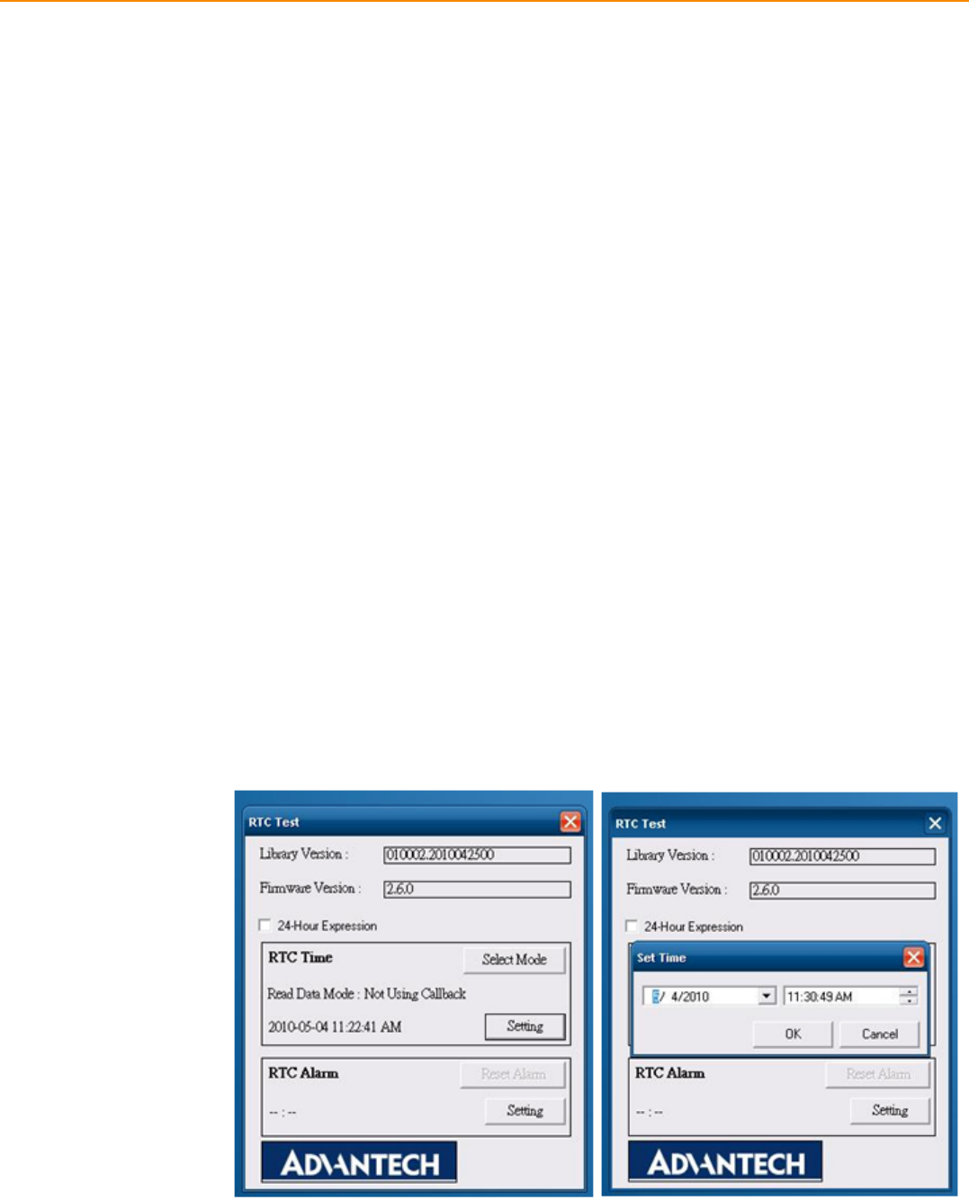
5.3 RTC Test
Execute “RTC test”
1. For RTC Time setting: You may set year, month, date, and time show as
below.
Figure 5.4 RTC test - 1 & 2
39 TREK-753 User Manual
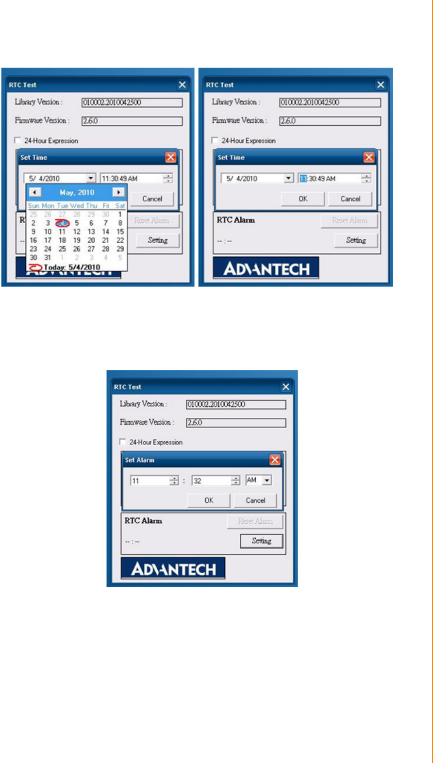
Chapter 5 Software Demo Utility Setup
Figure 5.5 RTC test - 3 & 4
2. RTC Alarm Setting: You may also set Alarm time; you may wake up the system
by the time you have set. Please refer to the below figure.
Figure 5.9 RTC test - 5

TREK-753 User Manual 40
5.4 Vehicle Power Management
5.4.1 Power Management Mechanism
The feature of Vehicle Power Management (VPM) is provided for users to fulfill the
special requirements on in-vehicle applications.
Ignition on/off
–Turn on the system by ignition
For the cases of in-vehicle applications, an ignition signal is often used to turn
on or shutdown the system. When the system is in an OFF state and ignition
is turn ON, the VPM controller will countdown ON_DELAY; once it counts to
zero, the system will be turned on.
–Shutdown the system by ignition
When the system is powered on and the ignition is turn off, the
OFF_EVENT_DELAY will start to count down. During this stage, if the igni-
tion is back to ON, the VPM controller will stop countdown and reset the
OFF_EVENT_DELAY value. If OFF_EVENT_DELAY counts to zero, the
VPM controller will send an event (power button press) to the system and
start to count HARD_OFF_DELAY. Application programs could watch this
event to do pre-defined tasks, like storing data and preparing to turn off the
system.
Once going into the HARD_OFF_DELAY stage, this process will be irrevers-
ible. And if HARD_OFF_DELAY counts to zero, the system power will be cut
off abruptly.
Low battery protection
To avoid draining out the car battery, low-battery protection is involved to ensure
the car battery is capable to start the vehicle. When the system is ON, the VPM
controller will monitor the car battery voltage. If the battery voltage is lower than
a programmable threshold (LOW_THRESHOLD), the VPM controller will go into
LOW_DELAY stage and start to count down. During the stage of LOW_DELAY
countdown, if battery voltage is back above LOW_THRESHOLD, the VPM con-
troller will stop counting down and exit. If LOW_DELAY counts to zero, the VPM
controller will send an event (power button press) to notify the system, go into
LOW_ HARD_DELAY stage and start to count down. Once LOW_
HARD_DELAY counts to zero, the VPM controller will cut off the system power
abruptly to avoid draining out the car battery.
The table below lists the user programmable parameters for VPM features:
Default value Acceptable range
ON_DELAY 2 seconds 1 ~ 18000 seconds
OFF_EVENT_DELAY 5 seconds 1 ~ 18000 seconds
HARD_OFF_DELAY 60 seconds 1 ~ 18000 seconds
LOW_THRESHOLD (12V mode) 11.42 V 10.09 ~ 12.25 V
LOW_THRESHOLD (24V mode) 22.44 V 21.11 ~ 23.28 V
LOW_DELAY 30 seconds 1 ~ 3600 seconds
LOW_ HARD_DELAY 60 seconds 1 ~ 3600 seconds

41 TREK-753 User Manual
Chapter 5 Software Demo Utility Setup
5.4.2 Power Management Utility Program
Execute IMCDemo.exe file, see the icon below.
TREK-753 User Manual 42
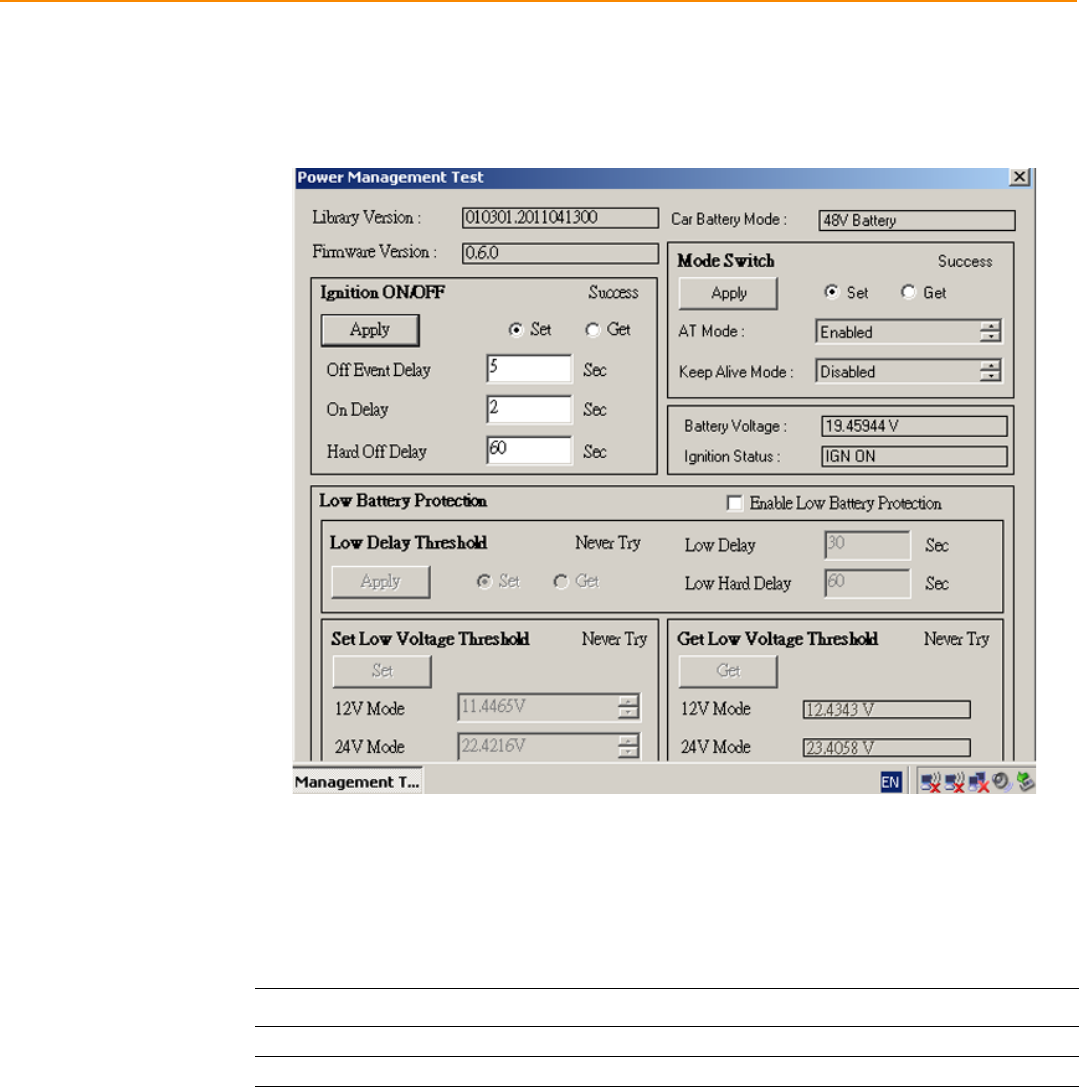
5.4.3 Power Management Parameter Settings
The parameters for power management on TREK-753 could be read or modified by
Demo utility (see the image below) or SDK/API.
Figure 5.10 Power management test utility
5.4.4 TREK-753 Power Consumption
OS: Windows Embedded Standard
Burn-in test V6.0
*Doesn’t support S1, S3, S4
Power mode Power input range Power consumption(Typical)
12V/24V 6V~36V/6A(max) 36 Watt
48V 18V~58V/2A(max) 36 Watt
43 TREK-753 User Manual
Chapter 5 Software Demo Utility Setup
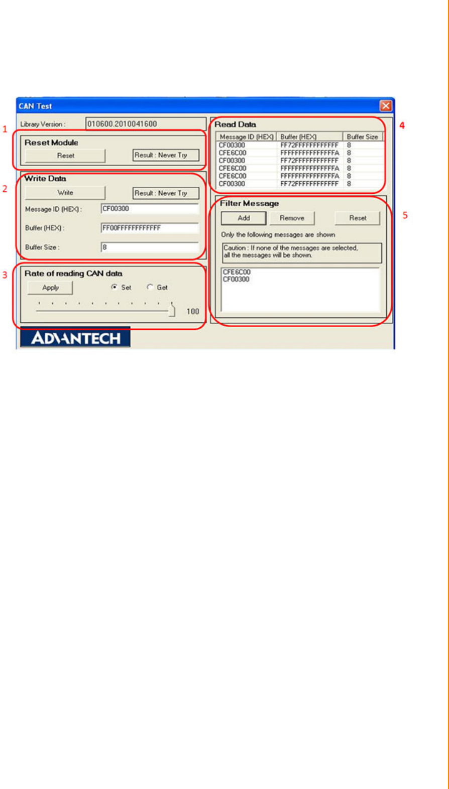
5.5 Execute CAN Demo Utility
Figure 5.11 CAN test
1. Reset the module
2. Transmit CAN message
3. Set the polling rate of CAN message reception
4. Received CAN message.
5. Set up the filter of CAN message (only show the message ID)
TREK-753 User Manual 44
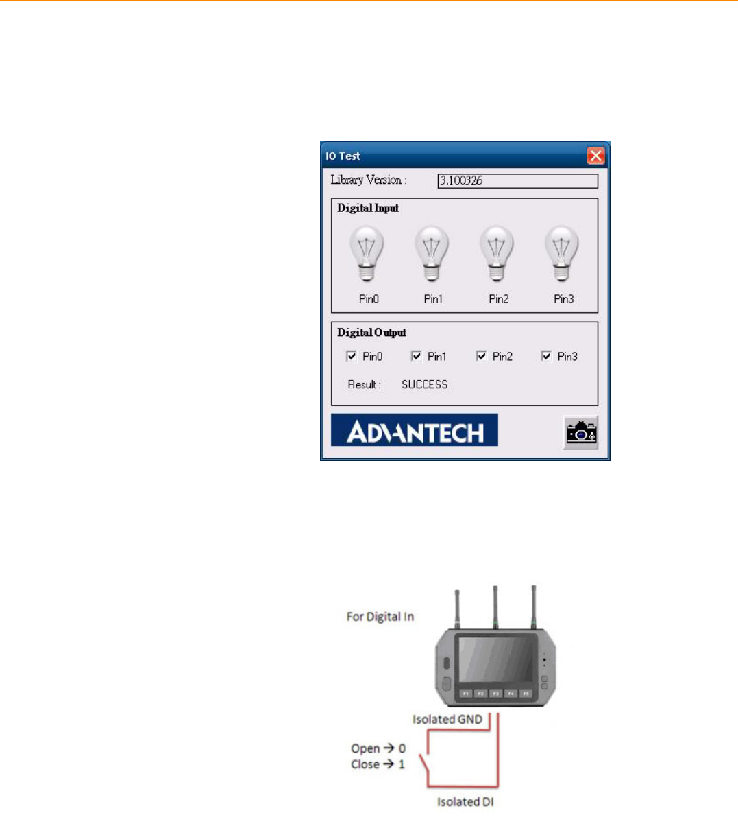
5.6 GPIO Test
1. To execute the I/O Test, connect GPIO loopback, click Pin0, connect the end
which reads the signal, the bulb should light up, like wise to Pin1~Pin3. Next
check the Digital output box to execute the same procedure. See figure 6.
Figure 5.12 DI/O test
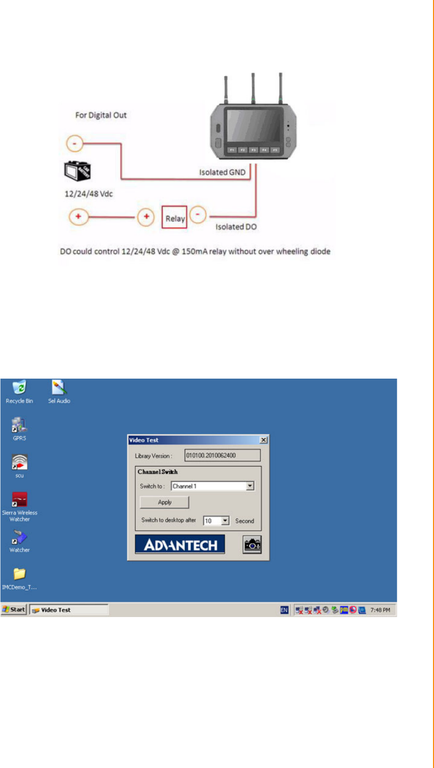
a. Digital Output ==> isolated relay driver output
b. Digital Input ==> isolated dry contact input
Figure 5.13 Digital in
45 TREK-753 User Manual
Chapter 5 Software Demo Utility Setup
Figure 5.14 Digital out
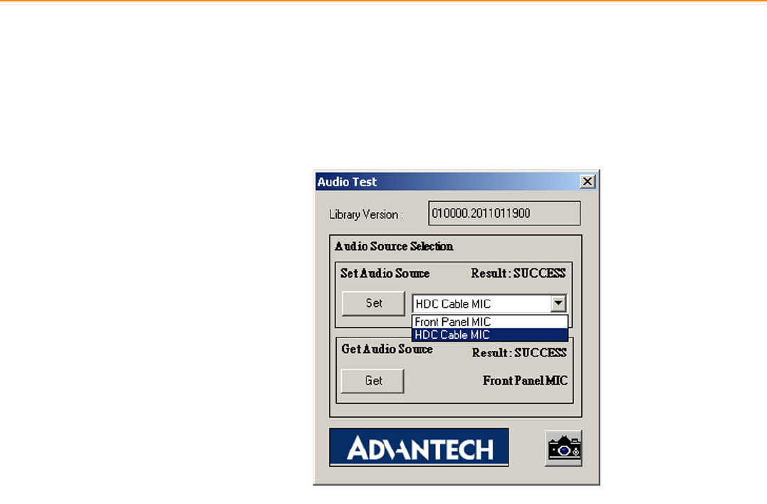
5.7 Video in Test
There are one video input, please connect camera to the port, CAM1. Choose Chan-
nel 1 on [Switch to], then the panel will show the image which camera1 has taken,
and it will recover to the same status after 10 sec.
Figure 5.15 Video test utility
TREK-753 User Manual 46
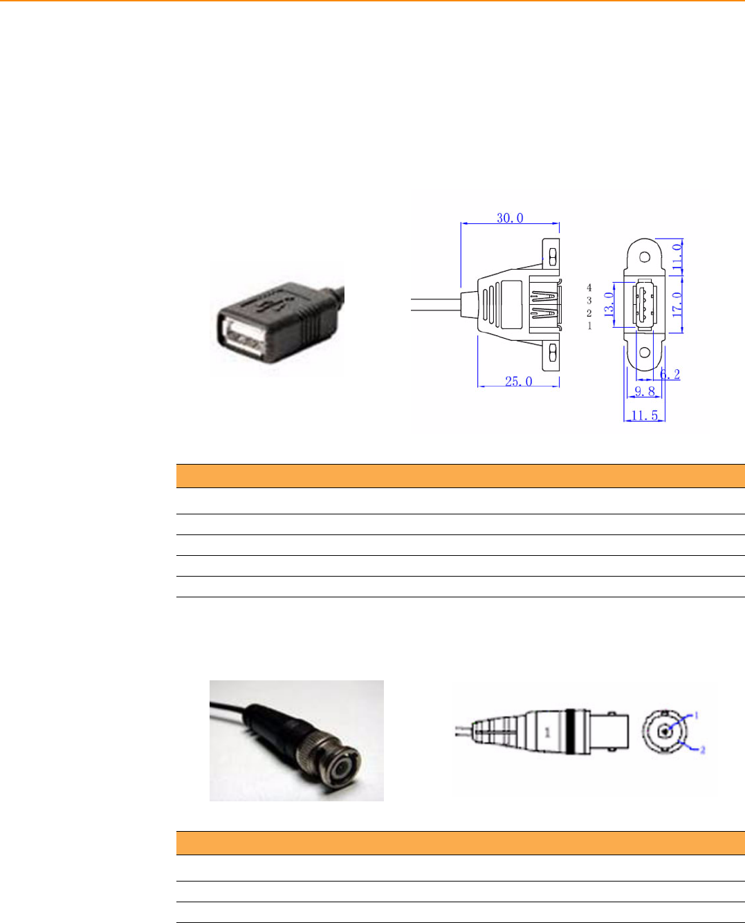
5.8 Audio Test
TREK-753 has a build-in microphone on front panel, and audio functions (Line out
and Line-in & Mic.in) can be extended to remote site by High Density Cable.Both of
Line out & Line in function are work directly when High Density cable connected. Mic,
in is able to works either front panel or from high density cable.

Appendix A
AHigh Density Cable Pin
Assignment
TREK-753 User Manual 48
High Density connecter of TREK-753 includes 48 wires in a 2-meter cable. It extends
many kinds and numbers IO port with standard type connecters for users.
At the host side, it builds a 3M 10150-3000 PE series 50 pin connecter with able to
connected with TREK-753. At the connecter side, there are
A.1 Standard USB A type female connecter
A.2 Video input, BNC female connecter
Table A.1: Standard USB A type female connecter
Pin Number Definition
1 +V5_USB
2 USB_D-
3 USB_D+
4 GND(Drain wire)
Table A.2: Video input, BNC female connecter
Pin Number Definition
1 CVBS_IN
2 GND(Drain wire)
49 TREK-753 User Manual
Appendix A High Density Cable Pin Assignment
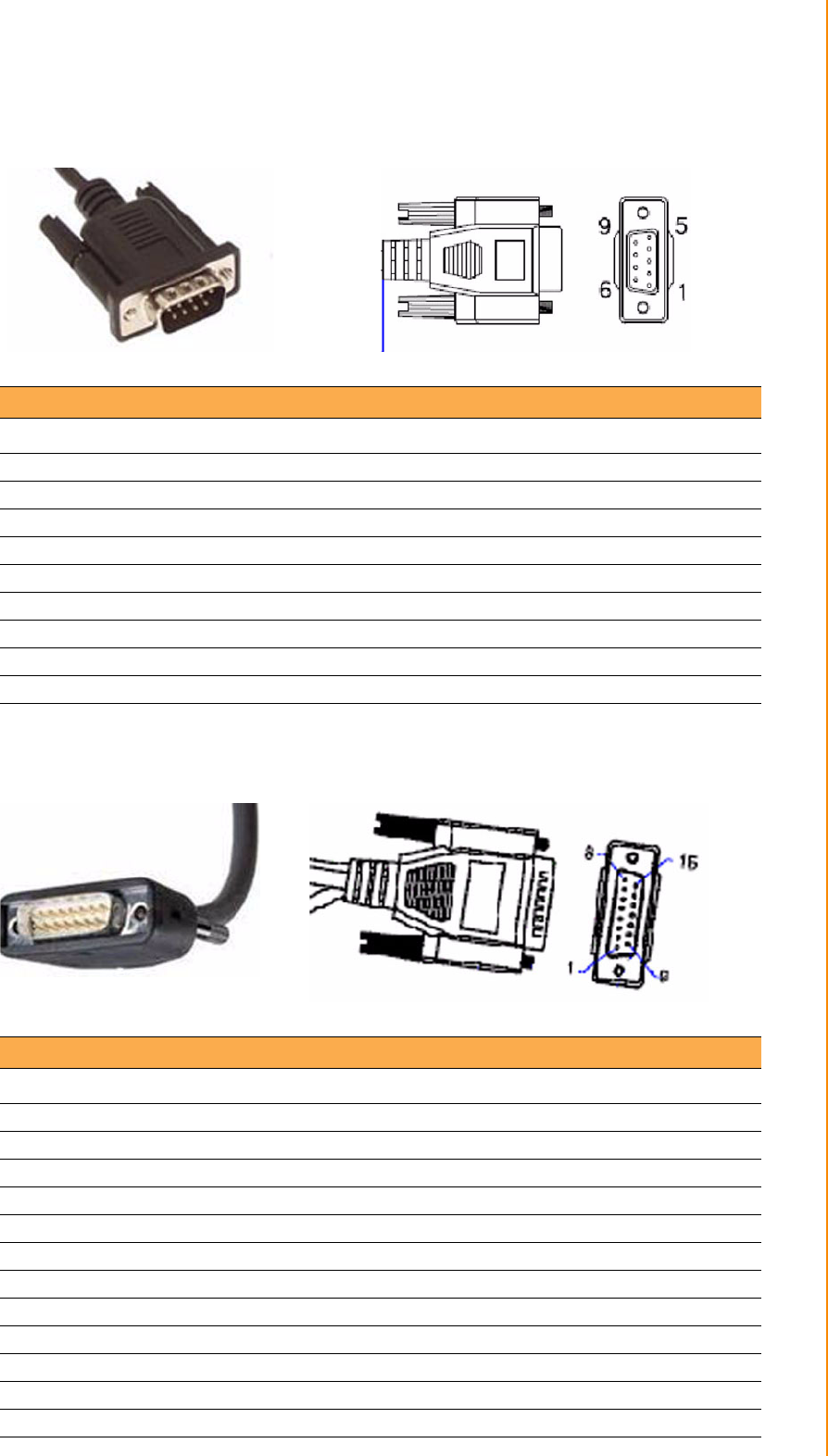
A.3 RS-232 connecter (DB9 male)
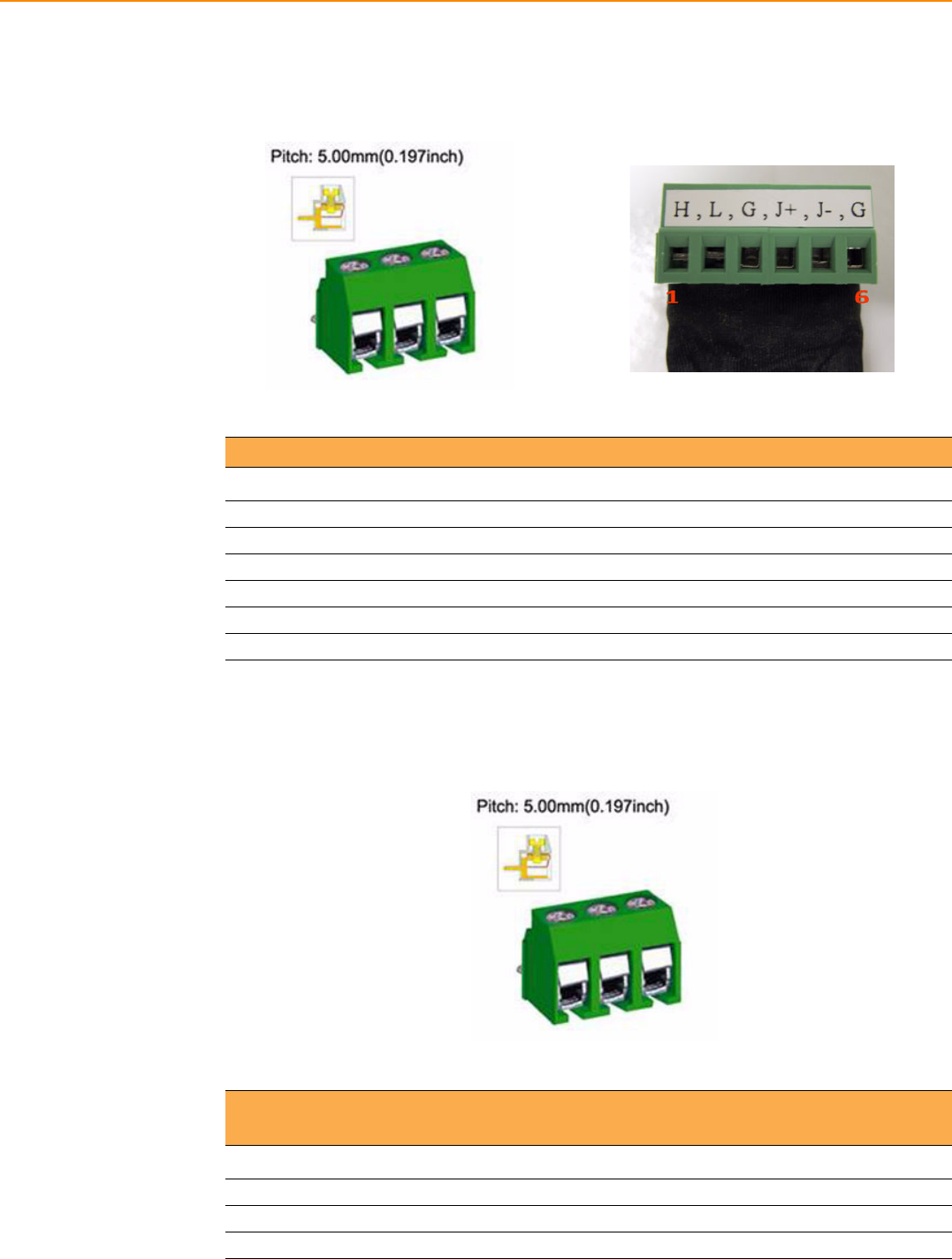
A.4 4DI /4DO & RS-485 (DB15 male type)
Table A.3: RS-232 connecter (DB9 male)
Pin Number Definition
1 RS232_DCD
2 RS232_RXD#
3 RS232_TXD#
4 RS232_DTR
5 GND(Drain wire)
6 RS232_DSR
7 RS232_RTS
8 RS232_CTS
9 RS232_RI
Table A.4: 4DI /4DO & RS-485 (DB15 male type)
Pin Number Definition
1ISO_DI1
2ISO_DI2
3ISO_DI3
4ISO_DI4
5GND_ISO
9ISO_DO1
10 ISO_DO2
11 ISO_DO3
12 ISO_DO4
13 RS485+
14 RS485-
15 GND(Drain wire)
TREK-753 User Manual 50
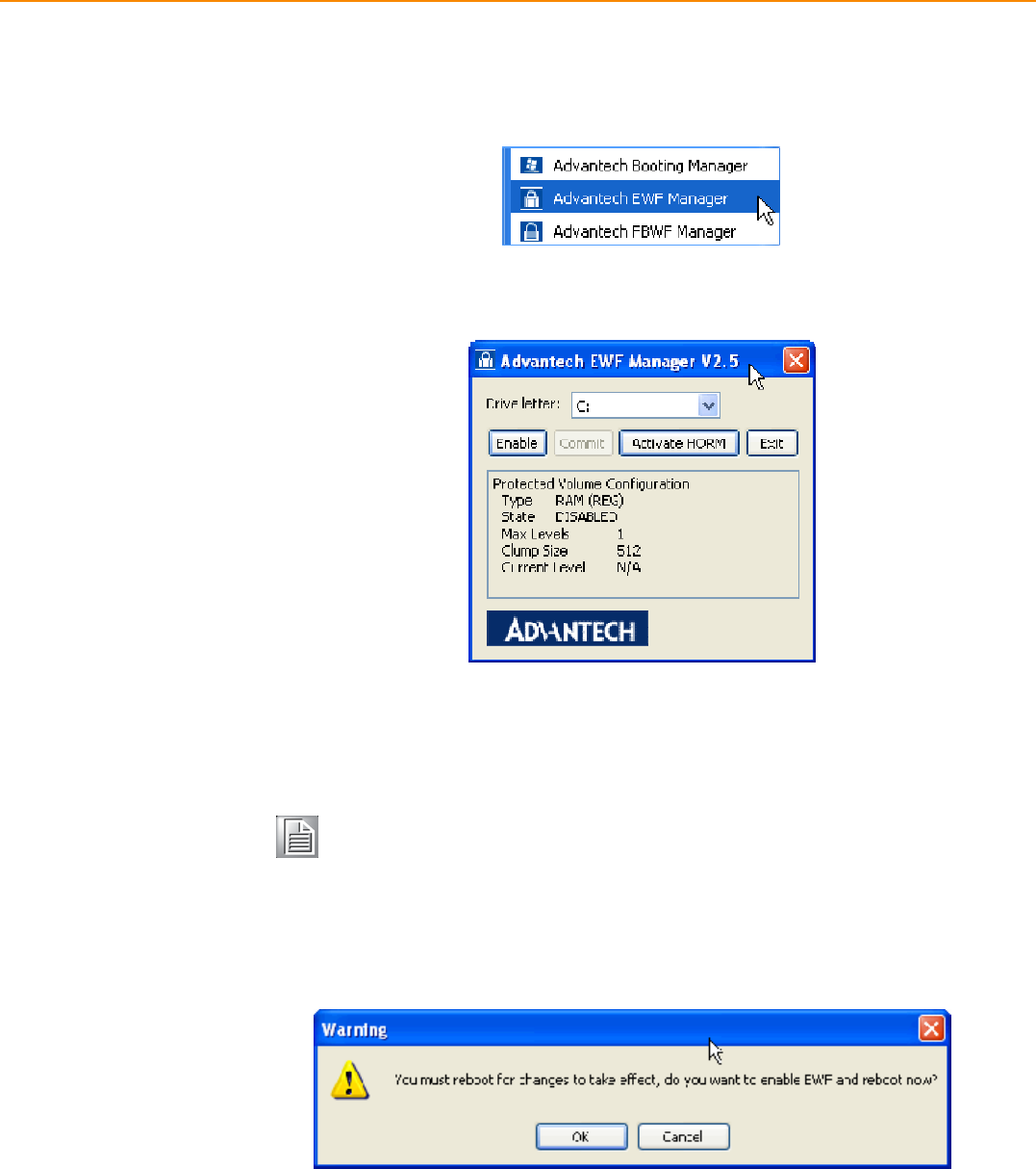
A.5 CAN Bus & J1708 (Terminal Block 6P, 5.08mm
pitch)
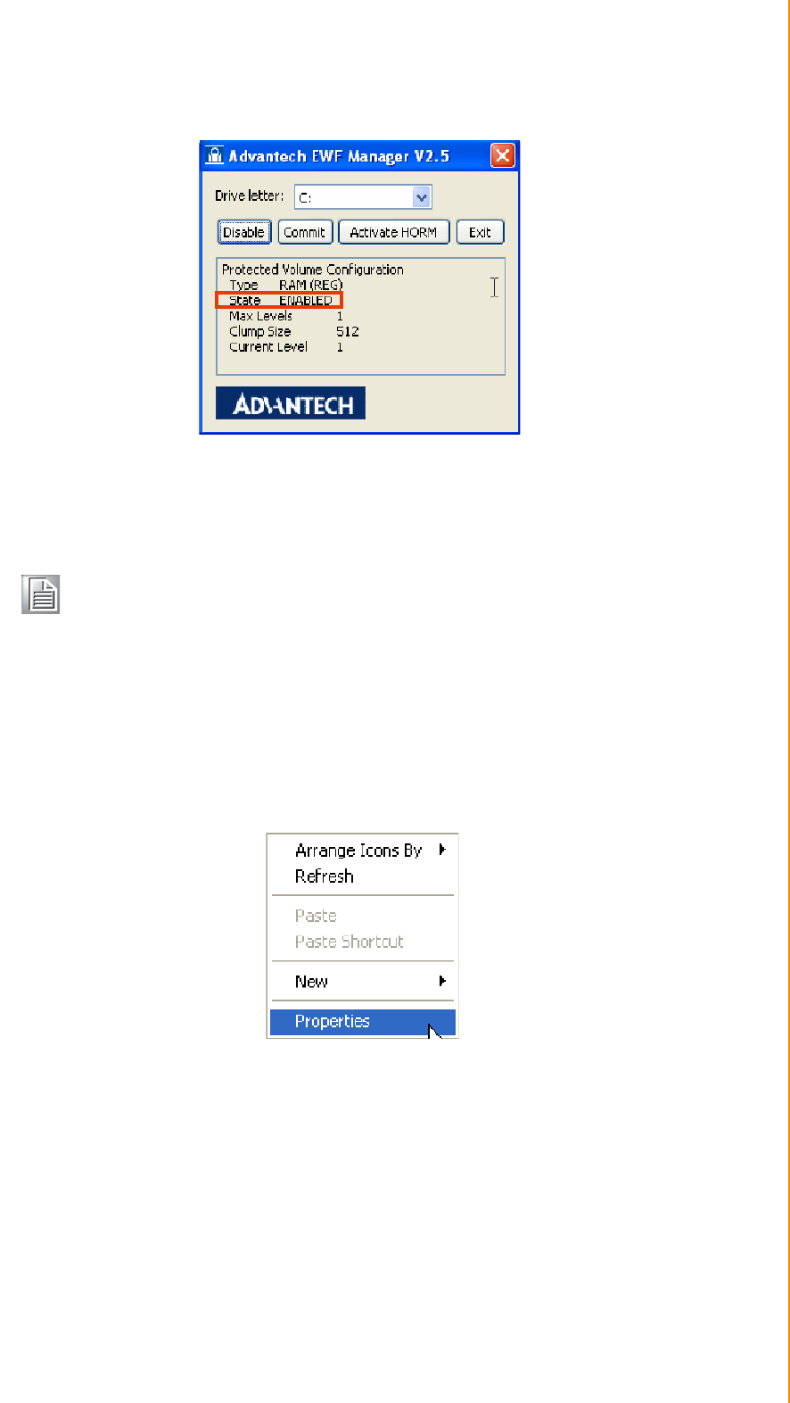
A.6 Power extension connecter (Terminal Block 3P,
5.08mm pitch)
Table A.5: CAN Bus & J1708 (Terminal Block 6P, 5.08mm pitch)
Pin Number Definition
1CAN_H (H)
2CAN_L (L)
3 GND (G)
4 J1708+ (J+)
5 J1708- (J-)
6 GND (G)
Table A.6: Power extension connecter (Terminal Block 3P, 5.08mm
pitch)
Pin Number Definition
1 +V12(26AWG)
2 GND(26AWG)
3 +V5(26AWG)

51 TREK-753 User Manual
Appendix A High Density Cable Pin Assignment
A.7 High Density & Connecter Pin List
High Denisity(50pin) connecter Jacks & IO conn./pin
No. Siganl Name Function / Conn. No.
1+V5(26AWG) Extended Power Terminal
Block 3P, 5.08mm pitch 3
2+V5_USB
USB tpye A
female connecter
1
3 GND(Drain wire) 4
4 USB_D+ 3
5 USB_D- 2
6 GND(Drain wire) Video input
BNC Connecter
2
7 CVBS_IN 1
8N/A
9 GND(Drain wire)
Line out jack10 LINEOUT_Left
11 LINEOUT_Right
12 LINEIN_Right
Line in jack
13 LINEIN_Left
14 MICIN Mic. In jack
15 GND(Drain wire)
DIO & RS-485
DB15 female
15
16 RS485- 14
17 RS485+ 13
18 GND(Drain wire)
CAN Bus & J1708
Terminal Block 6P, 5.08mm
pitch connecter
6
19 J1708- 5
20 J1708+ 4
21 GND(Drain wire) 3
22 CAN_L 2
23 CAN_H 1
24 N/A
25 N/A
26 +V12(26AWG)
Extended Power
Terminal Block 3P, 5.08mm
pitch
1
27 +V12(26AWG)
28 +V12(26AWG)
29 GND(26AWG) 2
30 GND(26AWG)
31 GND(26AWG)

TREK-753 User Manual 52
32 RS232_RI
RS-232 male Connecter
9
33 RS232_CTS 8
34 RS232_RTS 7
35 RS232_DSR 6
36 GND(Drain wire) 5
37 RS232_DTR 4
38 RS232_TXD# 3
39 RS232_RXD# 2
40 RS232_DCD 1
41 N/A
42 ISO_DO4
DIO & RS-485
DB15 female connecter
12
43 ISO_DO3 11
44 ISO_DO2 10
45 ISO_DO1 9
46 ISO_DI4 4
47 ISO_DI3 3
48 ISO_DI2 2
49 ISO_DI1 1
50 GND_ISO (26AWG) 5

Appendix B
BEWF(Enhanced Write
Filter)Manager SOP
TREK-753 User Manual 54
B.1 EWF(Enhanced Write Filter)Manager SOP
1. Open Start -> All Programs -> Advantech -> Advantech EWF Manager.
2. You will get a user interface as the following picture.
A. EWF function: If you want to protect your OS you can use the function. It will
recovery your OS after restarting OS.
EWF enable method:
1. Click Enable and UI will request restart OS
Note! Please check "C" volume is not protected.
55 TREK-753 User Manual
Appendix B EWF(Enhanced Write Filter)Manager SOP
2. After restarting OS you will discover EWF state become "Enable"
3. At this time, you can try to create folder or file and restart OS. You will discover
you can't modify data under C volume.
HORM(Hibernate Once and Resume Many): The function can always resume your
OS after hibernating, even shutdown or crash.
I Before using HORM you should set EWF "disable"
II Check "Enable hibernate"
1. Right-Click on desktop and click "Properties"
Note! If you want to write data at EWF enable state you can click Commit to
write data under C volume.
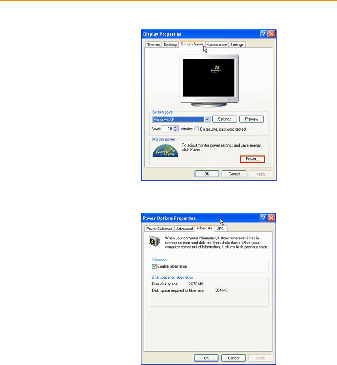
TREK-753 User Manual 56
2. Choose "Screen Saver" panel and click "Power”.
3. Check "Enable hibernate".
57 TREK-753 User Manual
Appendix B EWF(Enhanced Write Filter)Manager SOP
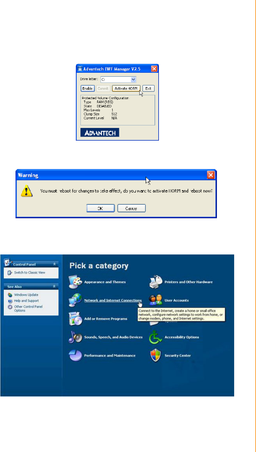
III Activate HORM
1. Open Start -> All Programs -> Advantech -> Advantech EWF Manager.
2. Click "Activate HORM".
3. Chick "OK" to reboot OS.
IV Check "Use the Welcome screen".
1. Open Start -> Control Panel.
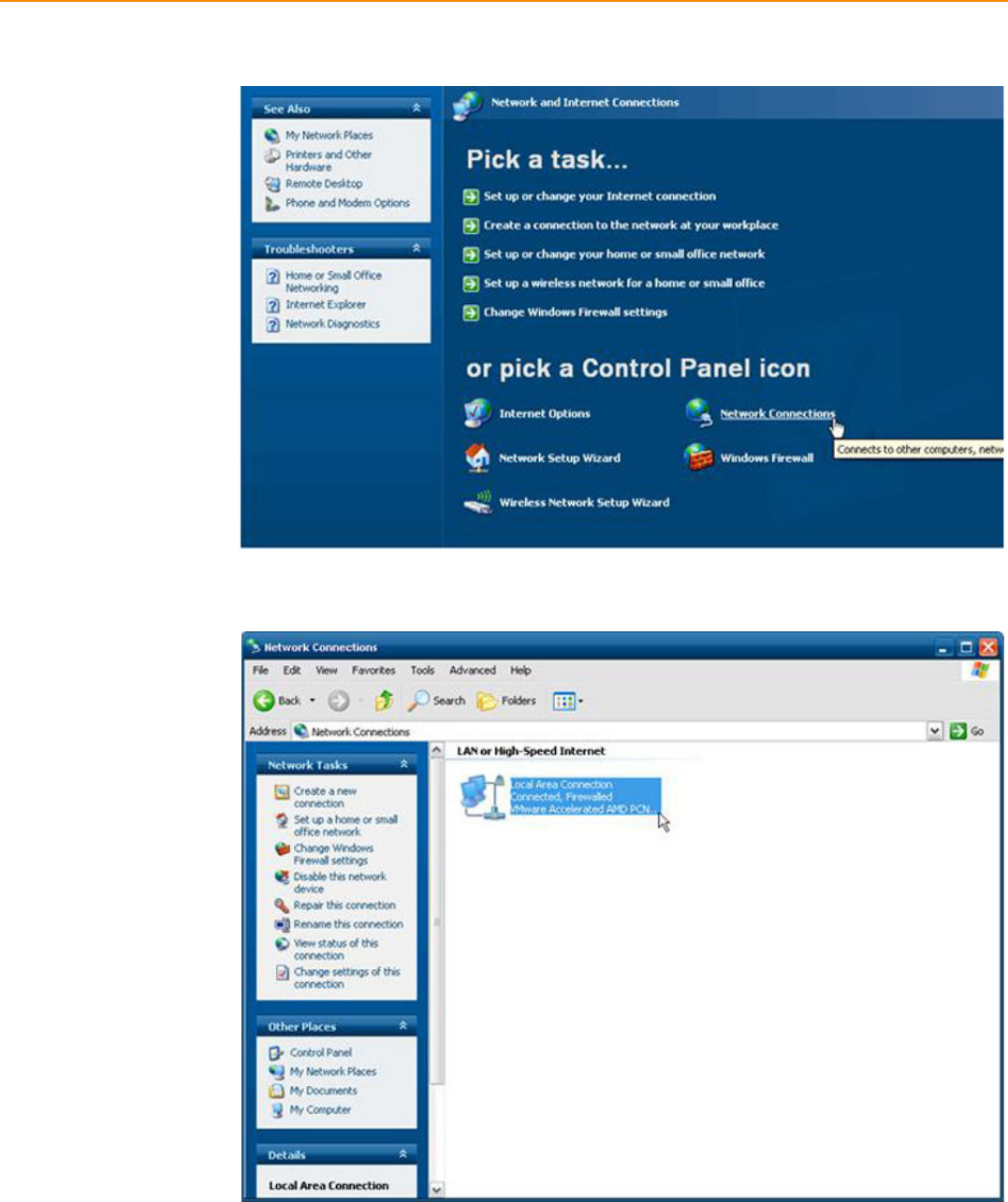
TREK-753 User Manual 58
2. Click "Network and Internet Connections".
3. Click "Network Connection".
59 TREK-753 User Manual
Appendix B EWF(Enhanced Write Filter)Manager SOP
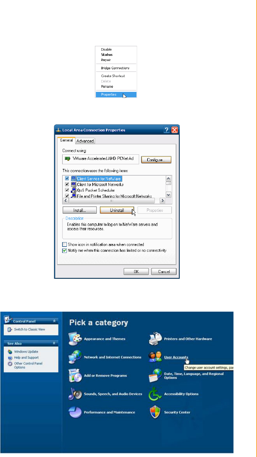
4. Right-Click on "Local Area Connection" and click properties.
5. Uninstall "Client Service for NetWare".
6. Click "Yes" to remove "Client Service for NetWare" and reboot OS.
7. Open Start -> Control Panel.
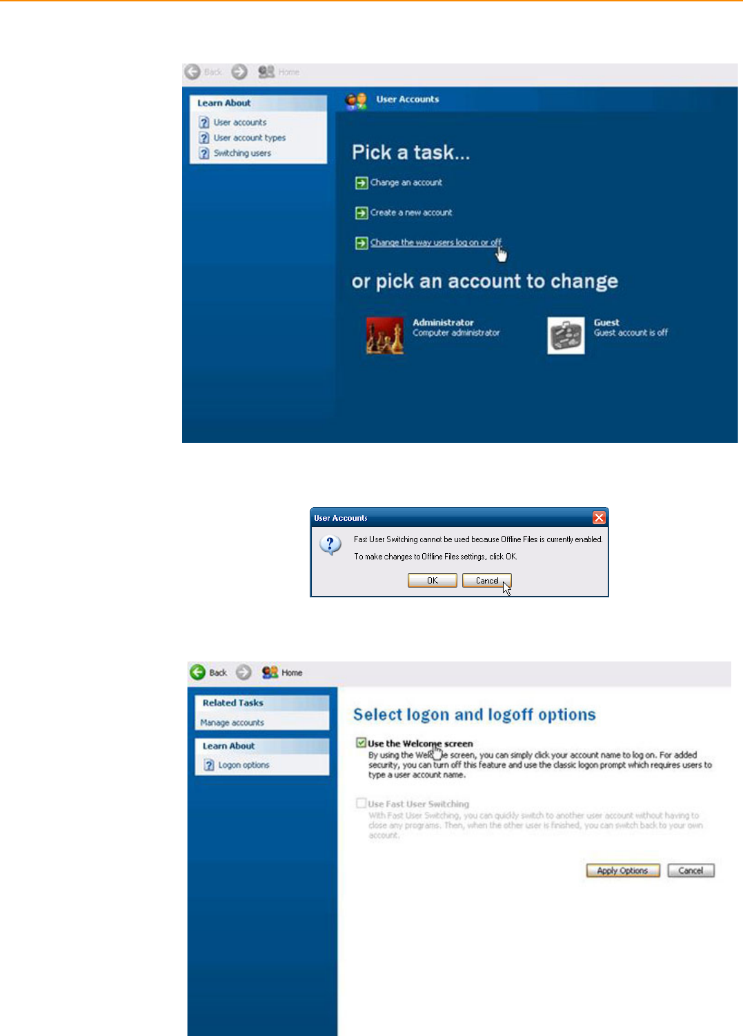
TREK-753 User Manual 60
8. Click "User Accounts"
9. Click "Cancel".
10. Check "Use the Welcome screen" and Click "Apply Options"
61 TREK-753 User Manual
Appendix B EWF(Enhanced Write Filter)Manager SOP
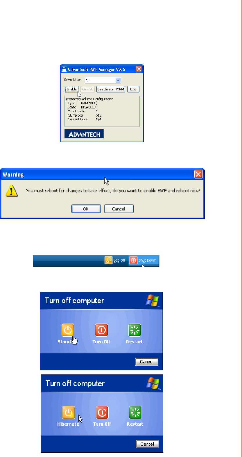
V Enable EWF
1. Open Start -> All Programs -> Advantech -> Advantech EWF Manager.
2. Click "Enable".
3. Click "OK" to reboot OS.
VI Run "Hibernate"
1. Open Start -> Shut Down
2. When you press "Shift" Standby will become Hibernate

TREK-753 User Manual 62
VII Enable HORM finish
VIII You can try to pull power cord after resuming. You will discover the OS always
been resuming

63 TREK-753 User Manual
Appendix B EWF(Enhanced Write Filter)Manager SOP

www.advantech.com
Please verify specifications before quoting. This guide is intended for reference
purposes only.
All product specifications are subject to change without notice.
No part of this publication may be reproduced in any form or by any means,
electronic, photocopying, recording or otherwise, without prior written permis-
sion of the publisher.
All brand and product names are trademarks or registered trademarks of their
respective companies.
© Advantech Co., Ltd. 2011

65