Advantech Co TREK773LTE Computer User Manual TREK 773 20151027
Advantech Co Ltd Computer TREK 773 20151027
UserManual.wiki
>
Advantech Co
>
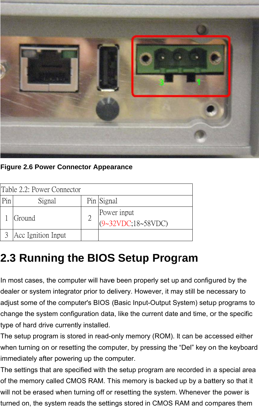
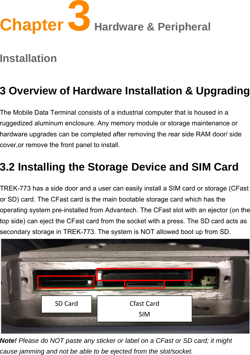
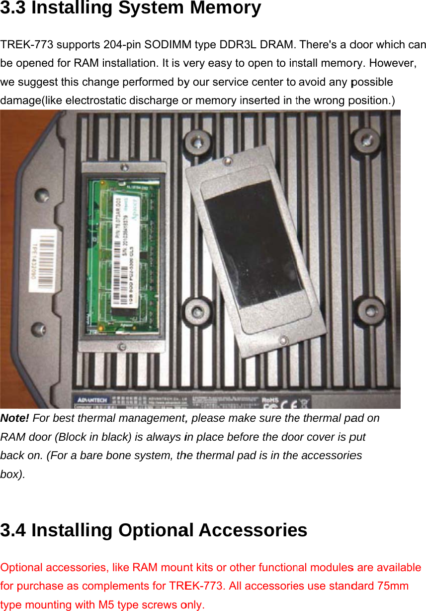
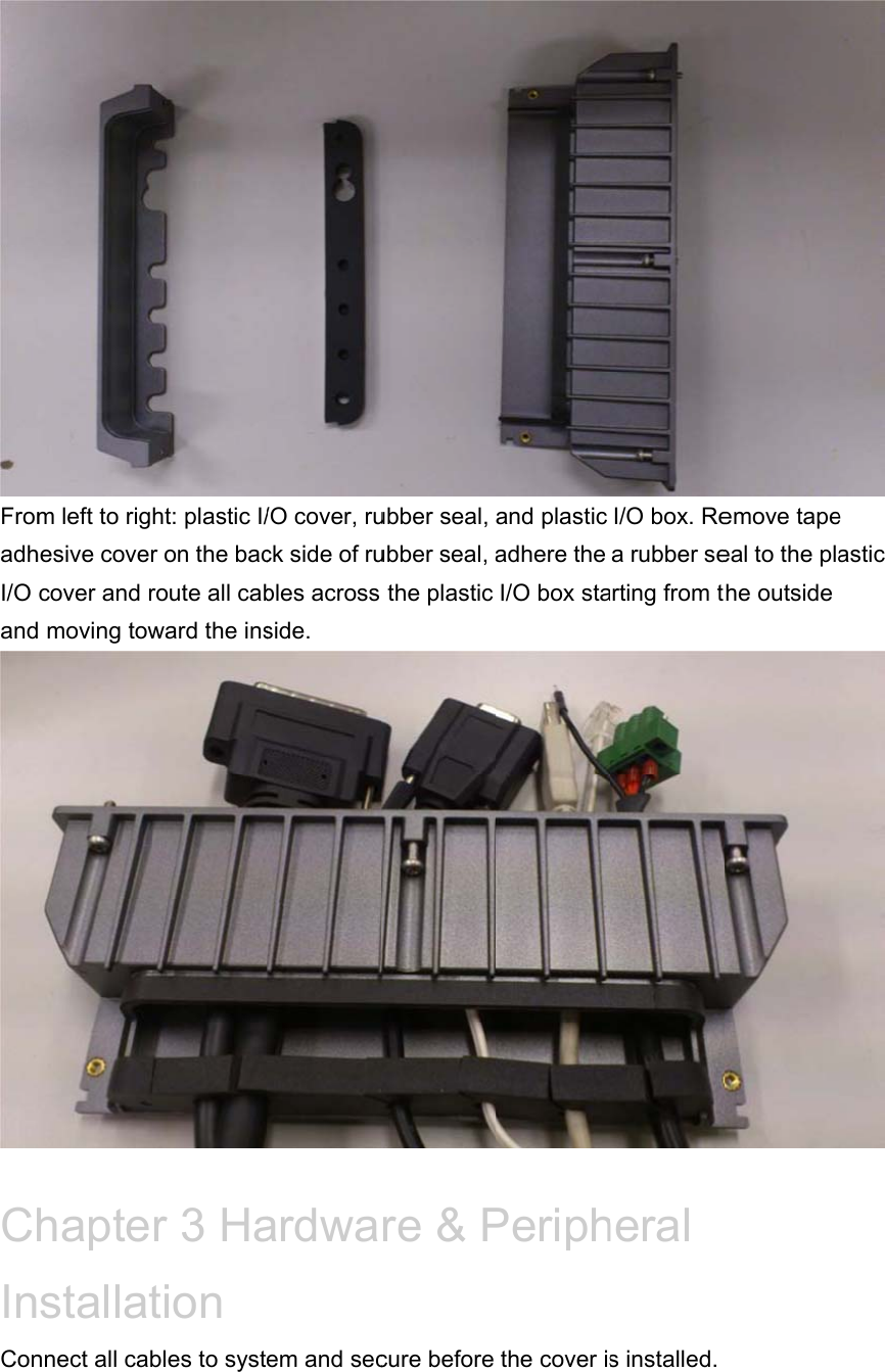
TREK773LTE User Manual
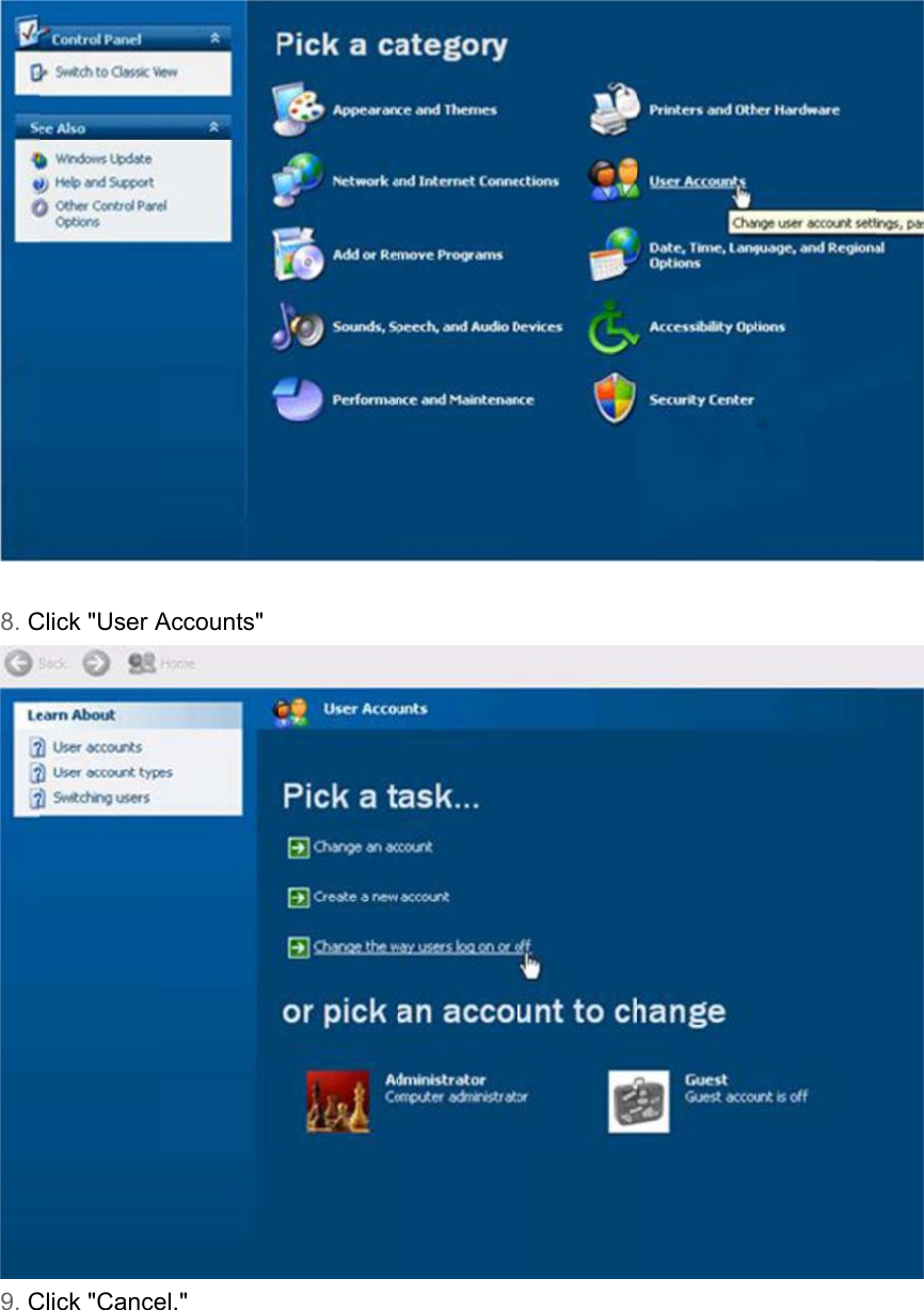
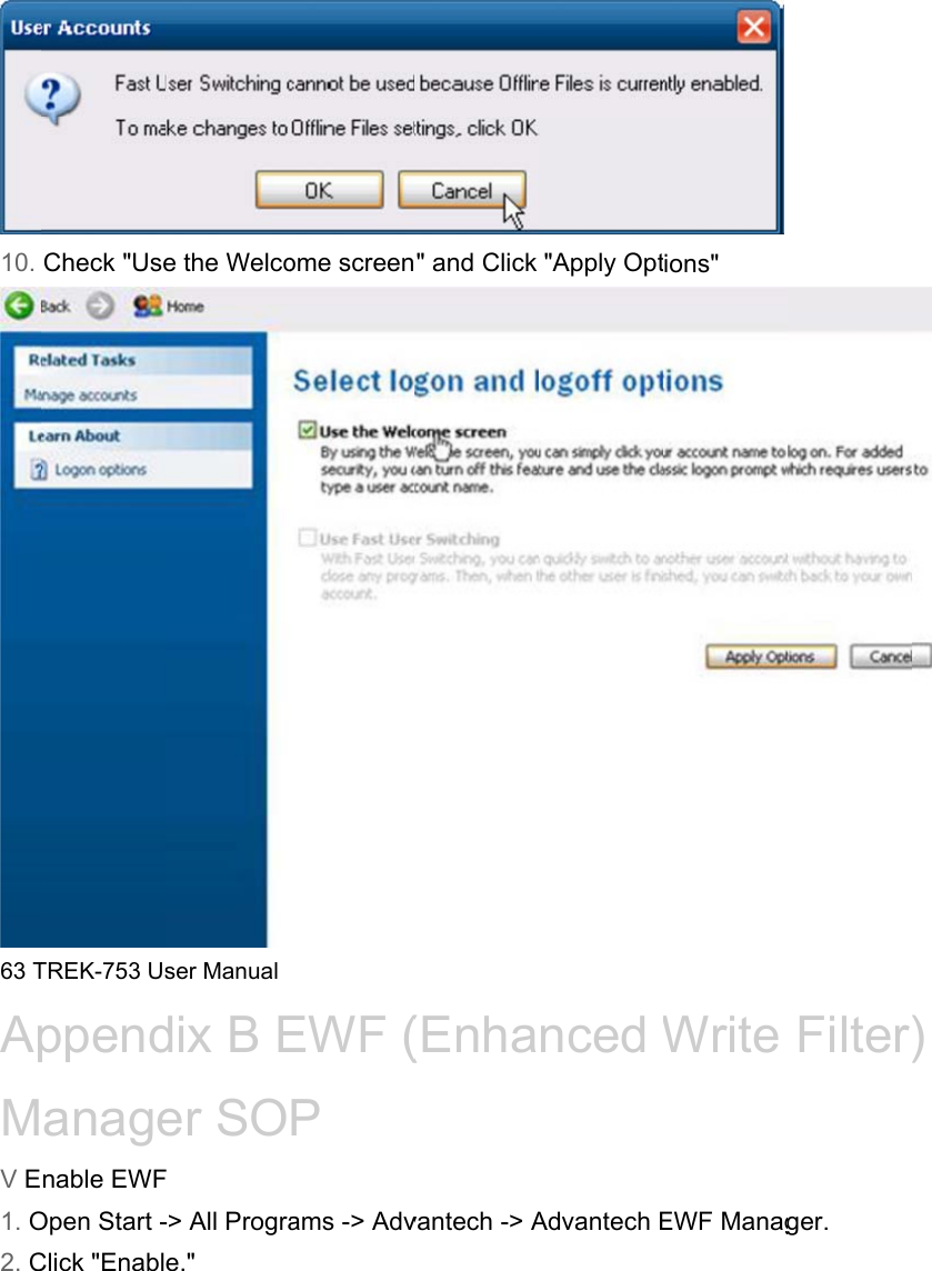
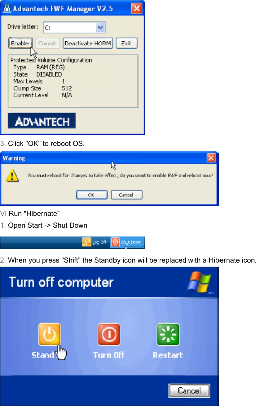
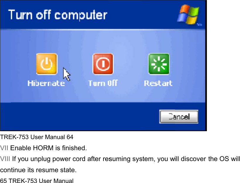
User Manual
Navigation menu
Upload a User Manual
Namespaces
Wiki Guide
HTML
PDF
Info
Views
User Manual
Discussion / Help
Navigation