Advantech Co TREK773LTE Computer User Manual TREK 773 20151027
Advantech Co Ltd Computer TREK 773 20151027
User Manual
TREK-773
7" All-in-one Mobile Data
Terminal
Copyright
The documentation and the software included with this product are copyrighted 2015
by Advantech Co., Ltd. All rights are reserved. Advantech Co., Ltd. reserves the right
to make improvements in the products described in this manual at any time without
notice. No part of this manual may be reproduced, copied, translated or transmitted
in any form or by any means without the prior written permission of Advantech Co.,
Ltd. Information provided in this manual is intended to be accurate and reliable.
However, Advantech Co., Ltd. assumes no responsibility for its use, nor for any
infringements of the rights of third parties, which may result from its use.
Acknowledgements
Intel and Atom are trademarks of Intel Corporation.
Microsoft Windows and MS-DOS are registered trademarks of Microsoft Corp.
All other product names or trademarks are properties of their respective owners.
Product Warranty (2 years)
Advantech warrants to you, the original purchaser, that each of its products will be
free from defects in materials and workmanship for two years from the date of
purchase.
This warranty does not apply to any products which have been repaired or altered by
persons other than repair personnel authorized by Advantech, or which have been
subject to misuse, abuse, accident or improper installation. Advantech assumes no
liability under the terms of this warranty as a consequence of such events.
Because of Advantech’s high quality-control standards and rigorous testing, most of
our customers never need to use our repair service. If an Advantech product is
defective,
it will be repaired or replaced at no charge during the warranty period. For out of-
warranty repairs, you will be billed according to the cost of replacement materials,
service time and freight. Please consult your dealer for more details.
If you think you have a defective product, follow these steps:
1. Collect all the information about the problem encountered. (For example, CPU
speed, Advantech products used, other hardware and software used, etc.) Note
anything abnormal and list any onscreen messages you get when the problem
occurs.
2. Call your dealer and describe the problem. Please have your manual, product,
and any helpful information readily available.
3. If your product is diagnosed as defective, obtain an RMA (return merchandise
authorization) number from your dealer. This allows us to process your return
more quickly.
4. Carefully pack the defective product, a fully-completed Repair and Replacement
Order Card and a photocopy proof of purchase date (such as your sales receipt)
in a shippable container. A product returned without proof of the purchase date
is not eligible for warranty service.
5. Write the RMA number visibly on the outside of the package and ship it prepaid
to your dealer.
Part No. Edition 1
Printed in Taiwan April 2012
Declaration of Conformity
CE
This product has passed the CE test for environmental specifications. Test conditions
for passing included the equipment being operated within an industrial enclosure. In
order to protect the product from being damaged by ESD (Electrostatic Discharge)
and EMI leakage, we strongly recommend the use of CE-compliant industrial
enclosure
products.
FCC Class B
Note: This equipment has been tested and found to comply with the limits for a Class
B digital device, pursuant to part 15 of the FCC Rules. These limits are designed to
provide reasonable protection against harmful interference in a residential installation.
This equipment generates, uses and can radiate radio frequency energy and, if
not installed and used in accordance with the instructions, may cause harmful
interference
to radio communications. However, there is no guarantee that interference
will not occur in a particular installation. If this equipment does cause harmful
interference
to radio or television reception, which can be determined by turning the equipment
off and on, the user is encouraged to try to correct the interference by one or
more of the following measures:
Reorient or relocate the receiving antenna.
Increase the separation between the equipment and receiver.
Connect the equipment into an outlet on a circuit different from that to which the
receiver is connected.
Consult the dealer or an experienced radio/TV technician for help.
This device complies with Part 15 FCC Rules.
Operation is subject to the following two conditions:
(1) this device may not cause harmful interference, and
(2) this device must accept any interference received, including interference may
cause undesired operation.
Technical Support and Assistance
1. Visit the Advantech web site at http://support.advantech.com where you can find
the latest information about the product.
2. Contact your distributor, sales representative, or Advantech's customer service
center for technical support if you need additional assistance. Please have the
following information ready before you call:
– Product name and serial number
– Description of your peripheral attachments
– Description of your software (operating system, version, application software,
etc.)
– A complete description of the problem
– The exact wording of any error messages
Warnings, Cautions and Notes
Document Feedback
To assist us in making improvements to this manual, we would welcome comments
and constructive criticism. Please send all such - in writing to: support@advantech.
com
Packing List
Before setting up the system, check that the items listed below are included and in
good condition. If any item does not accord with the table, please contact your dealer
immediately.
TREK-773 series Mobile Data Terminal
USB/LAN cable clip
Warranty card
Power cord: DC power inlet cable
WWAN or WLAN Antennas (by options)
“Drivers, Utilities and User Manual" CD-ROM
End User License Agreement (WES model), please download driver
and related document from http://support.advantech.com
Warning! Warnings indicate conditions, which if not observed, can cause personal
injury!
Caution! Cautions are included to help you avoid damaging hardware or losing
data. e.g.
There is a danger of a new battery exploding if it is incorrectly installed.
Do not attempt to recharge, force open, or heat the battery. Replace the
battery only with the same or equivalent type recommended by the manufacturer.
Discard used batteries according to the manufacturer's
instructions.
Note! Notes provide optional additional information.
Ordering Information
Safety Instructions
1. Read these safety instructions carefully.
2. Keep this User Manual for later reference.
3. Disconnect this equipment from any AC outlet before cleaning. Use a damp
cloth. Do not use liquid or spray detergents for cleaning.
4. For plug-in equipment, the power outlet socket must be located near the equipment
and must be easily accessible.
5. Keep this equipment away from humidity.
6. Put this equipment on a reliable surface during installation. Dropping it or letting
it fall may cause damage.
7. Do not leave this equipment in an environment where the storage temperature
is under -40° C (-40° F) or above 80° C (175° F); it may damage the equipment.
8. Do not operate this equipment in an environment temperature may over 60° C
(122° F). The surface temperature of metal chassis may be scorched or hot.
9. Make sure the voltage of the power source is correct before connecting the
equipment to the power outlet.
10. Position the power cord so that people cannot step on it. Do not place anything
over the power cord. The voltage and current rating of the cord should be greater
than the voltage and current rating marked on the product.
11. All cautions and warnings on the equipment should be noted.
12. If the equipment is not used for a long time, disconnect it from the power source
to avoid damage by transient overvoltage.
13. Never open the equipment. For safety reasons, the equipment should be
opened only by qualified service personnel.
14. If one of the following situations arises, get the equipment checked by service
personnel:
The power cord or plug is damaged.
Liquid has penetrated into the equipment.
The equipment has been exposed to moisture.
The equipment does not work well, or you cannot get it to work according to
the user's manual.
The equipment has been dropped and damaged.
The equipment has obvious signs of breakage.
15. This device complies with Part 15 of the FCC rules. Operation is subject to the
following two conditions:
(1) this device may not cause harmful interference, and
(2) this device must accept any interference received, including interference that
Part Number Description
TREK-773R-LWB8A0E TREK-773 full configuration with WW WWAN module
card(MC7304)
TREK-773R-LWB8B0E TREK-773 full configuration with US WWAN module
card(MC7354)
16. CAUTION: Always completely disconnect the power cord from your chassis
whenever you work with the hardware. Do not make connections while the
power is on. Sensitive electronic components can be damaged by sudden

power surges.
17. CAUTION: Always ground yourself to remove any static charge before touching
the motherboard, backplane, or add-on cards. Modern electronic devices are
very sensitive to static electric charges. As a safety precaution, use a grounding
wrist strap at all times. Place all electronic components on a static-dissipating
surface or in a static-shielded bag when they are not in the chassis.
18. CAUTION: Any unverified component could cause unexpected damage. To
ensure the correct installation, please always use the components (ex. screws)
provided with the accessory box.
19 .Cet appareil est conforme à la section 15 des réglementations de la FCC. Son
fonctionnement est soumis aux deux conditions suivantes :
(1) cet appareil ne doit pas causer d'interférences nuisibles, et (2) cet appareil doit
accepter toute autre interférence reçue, y compris les interférences pouvant entraîner
un fonctionnement non désiré.
ATTENTION !! Pour réduire le risque de décharge électrique, ne démontez pas
l'appareil. Aucune pièce interne n’est réparable par l'utilisateur. Référez-vous à une
personne qualifiée.
Safety Precaution - Static Electricity
Follow these simple precautions to protect yourself from harm and the products from
damage.
To avoid electrical shock, always disconnect the power from your system chassis
before you work on it. Don't touch any components on the main board or
other cards while the system is on.
Disconnect power before making any configuration changes. A sudden power
surge as you connect a jumper or install a card may damage sensitive electronic
components.
Warning! 1. Input voltage rated: 9 ~ 32 Vdc (12/24V power) or 18 ~ 58 Vdc
(48V power, option).
2. Transport: carry the unit with both hands and handle with care.
3. Maintenance: to properly maintain and clean the surfaces, use only
approved products or clean with a dry applicator.
4. CFast/SD/SIM card: Turn off the power before inserting or removing
5.This product is intended to be supplied by a Listed Power Adapter or DC power
source, rated 9-32Vdc, 6A minimum or 18-58Vdc, 3A minimum and Tma 60 degree C
Contents
Chapter 1General Information.................................................................................10
1.1Introduction...................................................................................................................10
1.2GeneralSpecifications...................................................................................................12
1.3Dimensions....................................................................................................................14
Chapter2System Setup..........................................................................................15
2.1AQuickTouroftheTREK‐773MobileDataTerminal...................................................15
2.2InstallationProcedures..................................................................................................19
2.2.1ConnectingthePowerCord...................................................................................19
2.2.2PowerConnector....................................................................................................20
2.3RunningtheBIOSSetupProgram..................................................................................21
Chapter3 Hardware & Peripheral Installation......................................................23
3.1OverviewofHardwareInstallation&Upgrading..........................................................23
3.2InstallingtheStorageDeviceandSIMCard..................................................................23
3.3InstallingSystemMemory.............................................................................................24
3.4InstallingOptionalAccessories......................................................................................24
3.5InstallingtheI/OCover..................................................................................................25
3.6InstallingWirelessOptions............................................................................................29
3.6.1WLAN......................................................................................................................30
3.6.2LTE(4G)...................................................................................................................32
3.6.3GPS..........................................................................................................................35
Chapter4 Pin Assignments.....................................................................................38
4.1RearSideConnectors....................................................................................................38
4.2PowerConnector...........................................................................................................38
4.3HighDensityConnector.................................................................................................39
4.4RS‐232Connector(COM9)............................................................................................40
4.5LEDIndicator.................................................................................................................41
Chapter 5 Software Demo Utility Setup.................................................................42
5.1Introduction...................................................................................................................42
5.2IVCPDemonstration......................................................................................................42
5.2.1Information.............................................................................................................43
5.2.2ModeControl.........................................................................................................44
5.2.3LowVoltageProtection..........................................................................................45
5.2.4EventDelay.............................................................................................................46
5.2.5Alarm......................................................................................................................49
5.2.6Watchdog...............................................................................................................51
5.2.7G‐Sensor.................................................................................................................52
5.2.8Peripheral...............................................................................................................53
5.2.9Storage....................................................................................................................54
5.2.10DigitalIO...............................................................................................................55
5.2.11P‐sensor................................................................................................................56
5.3VCILDemonstration.......................................................................................................57
5.3.1Portselection..........................................................................................................57
5.3.2Information.............................................................................................................58
5.3.3Option.....................................................................................................................59
5.3.4CAN/J1939/OBD2/J1708/J1587......................................................................60
5.4SmartDisplayDemonstration.......................................................................................63
5.4.1Information.............................................................................................................63
5.4.2Backlight.................................................................................................................64
5.4.3Hotkey....................................................................................................................65
5.4.4Peripheral...............................................................................................................66
5.5GPSDemonstration.......................................................................................................67
5.5.1Portselection..........................................................................................................67
5.5.2Information.............................................................................................................68
5.5.3NEMA......................................................................................................................68
Appendix A.................................................................................................................69
A.1StandardUSBATypeFemaleConnector......................................................................70
A.2Videoinput,BNCFemaleConnector.............................................................................70
A.3RS‐232Connector(DB9Male)(COM9).........................................................................71
A.44DI/4DO&RS‐485(DB15TypeMale)(COM5).............................................................71
A.5CANBus&J1708(TerminalBlock6P,5.08mmpitch)...................................................73
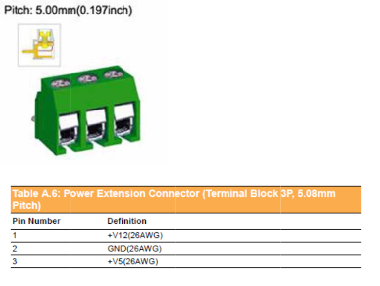
A.6PowerExtensionConnector(TerminalBlock3P,5.08mmpitch).................................74
A.7HighDensity&ConnectorPinList.................................................................................75
Appendix B.................................................................................................................77
B.1EWF(EnhancedWriteFilter)ManagerSOP..................................................................77
Chapter 1General Information
1General Information
1.1 Introduction
Advantech TREK-773 is a new generation, all-in-one 7” mobile data terminal
with touchscreen. Its compact and rugged industrial design is perfect for different
uses where space, vibration, transient power, and temperature fluctuations will
damage most computer equipment. TREK-773 is the higher performing cousin of the
award-winning TREK-773 with its Intel® Atom™ Bay Trail-I Series processor,
increased memory, the addition of an analog video input port, GbE LAN, and a rich
complement of I/O ports (additional COM ports, audio, CAN bus, and J1708).
TREK-773 has also been re-engineered to optimize internal space, gained by its
full-flat panel touchscreen; and it has moved the CFast/SD/SIM card slot to make it
externally accessible, allowing easy access without having to open the unit.
TREK-773 is built tough. It has an EN 60721-3-5 certification, and meets military
standards for vibration and shock. This ruggedness allows TREK to boldly go where
others dare not, opening a wide range of vertical market applications. TREK-773 is
suitable for taxi and bus transport, in vehicle fleets of all types, in long-haul trucking,
and as an affordable solution to heavy duty applications. TREK-773 is designed to
operate flawlessly in transient power conditions. It supports 12/24 V options,
operating from 9 ~ 32 volts, and it is ISO7637-2 and SAEJ1113 compliant. With
power-on/power-off delay features which are software configurable, TREK holds its
own in unstable power conditions. And TREK can operate in the temperature
extremes found in harsh environments.
I/O
Connecto
r
r
s
Chapter 1 General Information
1.2 General Specifications
Key Features
7" WVGA LCD with 5 programmable, adjustable brightness hot keys
Support Windows Embedded System 8(WES8), Fedora 18 Remix
Vehicle diagnostics interface with CAN Bus(Raw CAN, J1939, OBD-II/ISO 15765)
and J1708 (J1587) protocols
Built-in GNSS, WLAN, Bluetooth, NFC, and LTE WWAN modules
12V/24V option: 9~32V input range compliant with IOS7637-2 & SAE J1113
standards
48V option: 18~58V input range for specific applications
Fanless and ruggedized aluminum chassis, able to work in -30° C ~ 60° C
IP54 rating for the entire system, giving protection in harsh environments subject
to shock and vibration (Passed EN60721-3-5 5M3 Shock/vibration 100G/4G
test).
Specifications
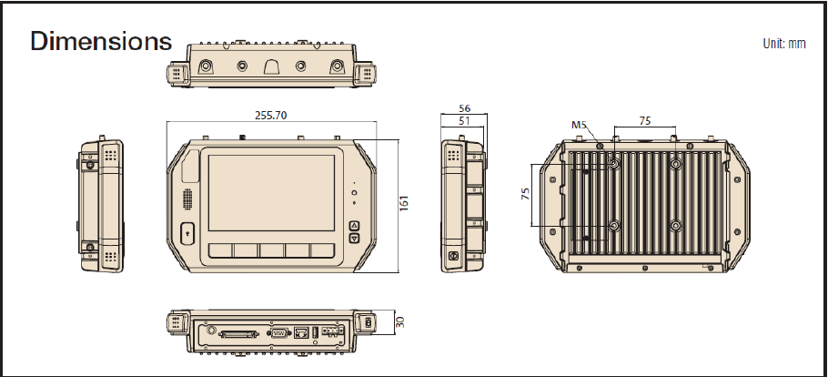
Dimensions: (W x H x D) - 255.7 x 161 x 56 mm (10.04" x 6.30" x 2.20")
Weight: 2.2 kg (max.)
Power features:
– Input voltage: 9 ~ 32 Vdc, supports ignition cold crank
– Supports Ignition on/off
– Supports low battery shut-down protection threshold (optional)
– Supports power off event delay
– Supports power on delay
– Supports power low delay
– Supports power low hard delay
– Supports hard off delay
CPU/Chipset: Industrial Intel Atom E3826 1.46GHz
Chipset: On board Intel Bay Trail-I Serial
OS: Windows Embedded System 8(WES8), Fedora 18 Remix
RAM: Support up to 4GB DDR3L-1600 memory module (Default configuration:
2GB)
Storage:
– 1 x SD card with external access (not for boot device)
– 1 x external accessible CFast (boot device)
– 1 x SIM card socket for LTE
LCD: Display Type 7" 16:9 industrial degree TFT LCD, 800x480 resolution
Touchscreen: Type 4-wire Analog resistive, continuous resolution, with 3H and
IK06 (drop ball 510g @300mm) supported
I/O Functions:
– 1 x video input port for rear view monitor (Note: bypasses video to screen,
does not support video recording)
– 1 x RS-232 COM port from rear I/O; 1 x RS-232 COM port; 1 x RS-485 port
with high density connector.
– 1 x USB 2.0 port from front panel; 1 x USB 3.0 port from rear I/O; 1x USB 2.0
with high density connector
– 1 x 100/1000-T Gb LAN by RJ-45 connector
– 1 x CAN Bus Support Raw CAN, J1939, OBD-II/ISO 15765 with high density
connector
– 1 x J1708 with high density connector
– 1 x built-in 2.0w speaker and 1 x built-in microphone in front panel
– 1 x Line-in/Line-out/Mic-in interface with high density connector or switch to
high density connector (via software)
– 5 x green lighted, programmable function keys, 2 x for LCD brightness control
– 1x light sensor on front cover for auto LCD brightness control
– 1x G-sensor on front cover for G value detection
– 4 x isolated DI & 4 x isolated DO connectors
RF Functions:
GPS:Built-in uBlox MAX-M8Q GPS module with external antenna in I/O plate
Bluetooth: Built-in Class 2 Bluetooth V4.0 LE, V3.0+HS, V2.1+EDR module
WWAN:
– LTE module; Sierra wireless MC73xx with SMA type connector
WLAN: Built-in 802.11a/b/g/n module with SMA type connector
Power Supply:
– Input Voltage 12V/24V option supports 9~32 V power design with
ISO7637-2 & SAE J1113 compliant
– 48v option support 18~58V input for specific application (Optional)
Mechanical Design:
– Aluminum chassis, optional, to support entire system IP54 rating with an
extended I/O cover
– Weight- under 2.2 kg (~4.85 lbs)
– Dimensions (W x H x D) - 255.7 x 161 x 56 mm (10.04" x 6.30" x 2.20")
Environmental Specifications:
– Operating Temperature : -30° C ~ 60° C
– Relative Humidity 95% @ 40° C (No condensing)
– Vibration & Shock: MIL-STD-810G (US highway truck), Method 516.5,
– SAE J1455, Class 5M3 according DIN EN 60721-3-5 (Lv.2 100G, 6ms,
shock)
Chapter 1 General Information
1.3 Dimensions
Figure 1.1 TREK-773 Dimensions
Chapter2System Setup
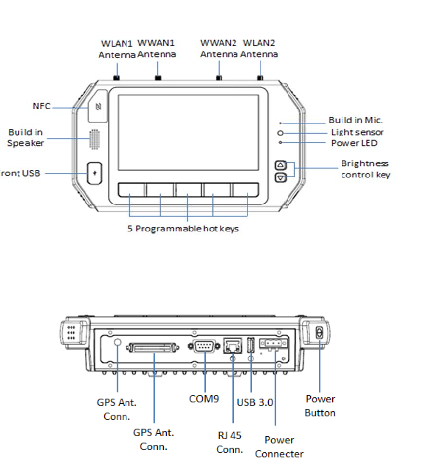
2.1 A Quick Tour of the TREK-773 Mobile Data
Terminal
Before starting to set up the Mobile Data Terminal, take a moment to become familiar
with the locations and functions of the controls, drives, connectors and ports, which
are illustrated in the figures below. When the Mobile Data Terminal is placed inside
truck glove cabinet or under the passenger’s seat next to the driver, its front appears
as shown in Figure 2.1.
Figure 2.1 Front View of TREK-773

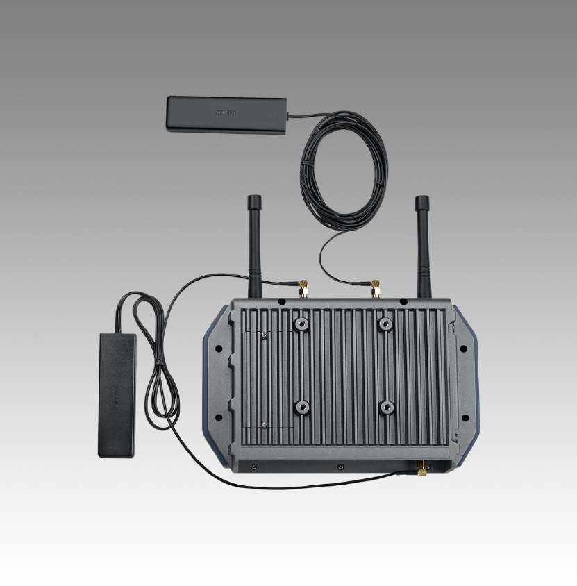
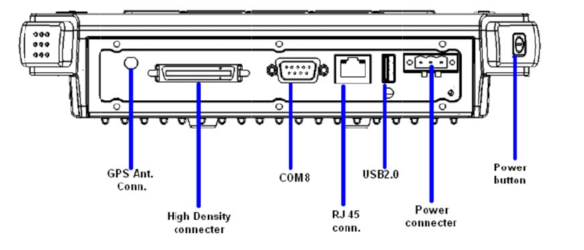
Figure 2.2 Rear View of TREK-773
Chapter 2 System Setup
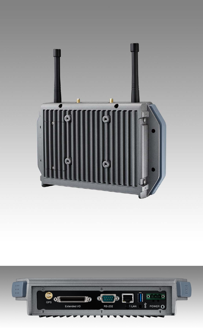
Figure 2.3 Side View of TREK-773
Figure 2.4 Bottom View of TREK-773
2.2 Installation Procedures
When you install TREK-773, the first step is to connect the power and ignition
correctly.TREK-773’s power cable is designed to connect to the battery directly.
TREK-773 can be switched ON/OFF both by the ignition signal or its power button.
Note! TREK-773 power input supports 12V/24V & 48V DC input. The default
setting is for 12V or 48V (option board) only. If customer needs 24V DC
input, please contact regional sales or distributors to customize in
advance.
Note! The fuse in the power cable for a 12V/24V (6A) and a 48V (3A) system
is different. Please check the fuse in your power cable before the system
is powered on
Caution!Usesuitablemountingapparatustoavoidriskofinjury.
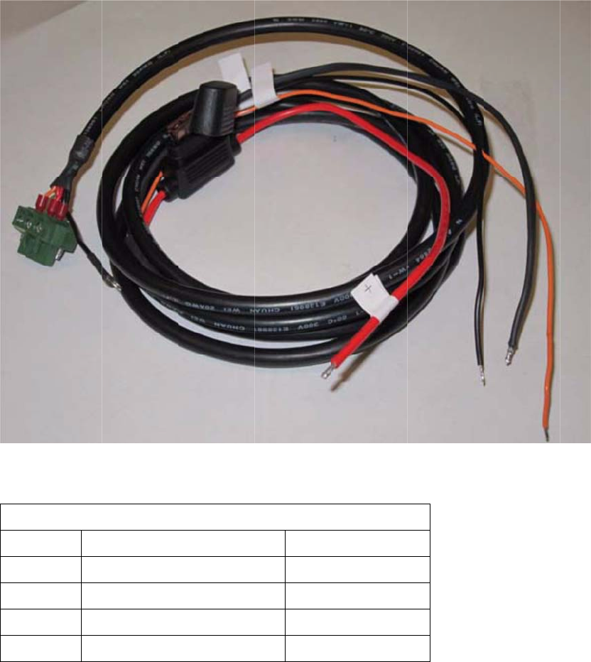
2.2.1 Connecting the Power Cord
Connect the three pin waterproof power cord to the DC inlet of TREK-773. On the
open-wire end, one pin is reserved for positive voltage and is marked "+" which
needs to be connected to the power "+" side; one pin is reserved for ground and is
marked "-"; which needs to be connected to the power "-" side. And, one pin is
reserved for the ignition signal with an “ignition” mark. There's an independent
"Shield" pin in the power cable; please fix it to the O-ring which is beside the TREK-
773 power connector.
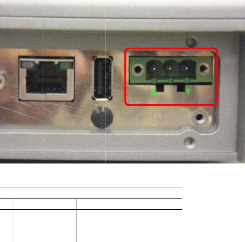
Note! Ignition on/off setting: The TREK-773 supports an ignition on/off function
so that you can power on/off the TREK-773 via the ignition signal/voltage.
Connector : DECA Switchlab ME050-50803
Mating connector: MC101-50803-3Y
Fig
u
C
h
2.
2
TR
E
igni
t
fro
m
mo
r
u
re 2.5 Po
w
Ts
a
PIN
1
2
3
4
h
apte
2
.2 Powe
E
K-773 ca
n
t
ion. There
m
fluctuatin
g
r
e power m
a
w
er Conne
a
ble 2.1 Pin
Def
i
S
h
Ig
n
r 2 S
y
r Conne
n
be power
e
is a 5 seco
g
power su
p
a
nagemen
t
ctor Phot
o
Definition
o
nition
+
h
ield
-
n
ition
y
stem
c
tor
e
d on/off fro
nd delay w
h
p
ply which
m
t
details, pl
e
o
o
f Power C
o
Setu
p
o
m the pow
e
hen using i
g
m
ight impa
c
e
ase see P
o
o
rd
Color
Red
Black
Black
Orange
p
e
r button o
r
g
nition on/
o
c
t or dama
g
o
wer mana
g
directly fro
o
ff. This av
o
g
e system
o
g
ement in
C
m the vehi
c
o
ids impact
o
peration.
F
C
hapter 5.
c
le
F
o
r
Fig
u
Ta
b
Ta
b
Pin
1
3
2.
3
In
m
de
a
adj
u
cha
typ
e
Th
e
wh
e
im
m
Th
e
of t
h
will
tur
n
u
re 2.6 Po
w
b
le 2.1: Pi
n
b
le 2.2: Pow
e
Si
g
Ground
Acc Igniti
o
3
Run
n
m
ost cases,
a
le
r
or syst
e
u
st some o
f
nge the sy
s
e
of hard dr
e
setup pro
g
e
n turning
o
m
ediately a
ft
e
settings t
h
h
e memory
not be era
s
n
ed on, the
w
er Conne
n
Definiti
o
e
r Connect
o
g
nal
o
n Input
n
ing th
the compu
e
m integrat
o
f
the comp
u
s
tem config
ive currentl
y
g
ram is sto
r
o
n or resetti
n
ft
er powerin
h
at are spe
c
called CM
O
s
ed when t
u
system rea
ctor Appe
a
o
n of Pow
r
Pin Sig
n
2 Pow
(9~
3
e BIO
S
ter will hav
e
o
r prior to d
e
ter's BIOS
uration dat
a
y
installed.
r
ed in read-
o
n
g the com
g up the c
o
c
ified with t
h
O
S RAM. T
u
rning off o
r
d
s the setti
n
a
rance
w
er Cord
n
al
w
er input
3
2VDC;18~
5
S
Setu
p
e
been pro
p
e
livery. Ho
w
(Basic Inp
u
a
, like the c
o
nly memo
puter, by p
r
o
mputer.
h
e setup pr
o
his memor
y
r
resetting t
h
ngs stored
5
8VDC)
p
Prog
p
erly set u
p
w
ever, it m
a
u
t-Output S
y
urrent date
r
y (ROM). I
r
essing the
o
gram are
r
y
is backed
h
e system.
in CMOS
R
r
am
and config
a
y still be n
e
y
stem) setu
and time,
o
t
can be ac
c
“Del” key o
r
ecorded in
up by a ba
t
Whenever
R
AM and co
g
ured by th
e
e
cessary to
u
p program
s
o
r the speci
c
cessed eit
h
o
n the keyb
o
a special
a
t
tery so tha
the power
i
o
mpares th
e
e
s
to
fic
h
e
r
o
ard
a
rea
t it
s
e
m
to the equipment check conducted during the power on self-test (POST). If an error
occurs, an error message is displayed on screen, and the user is prompted to run the
setup program.
Chapter3 Hardware & Peripheral
Installationa
3 Overview of Hardware Installation & Upgrading
The Mobile Data Terminal consists of a industrial computer that is housed in a
ruggedized aluminum enclosure. Any memory module or storage maintenance or
hardware upgrades can be completed after removing the rear side RAM door/ side
cover,or remove the front panel to install.
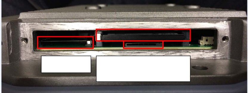
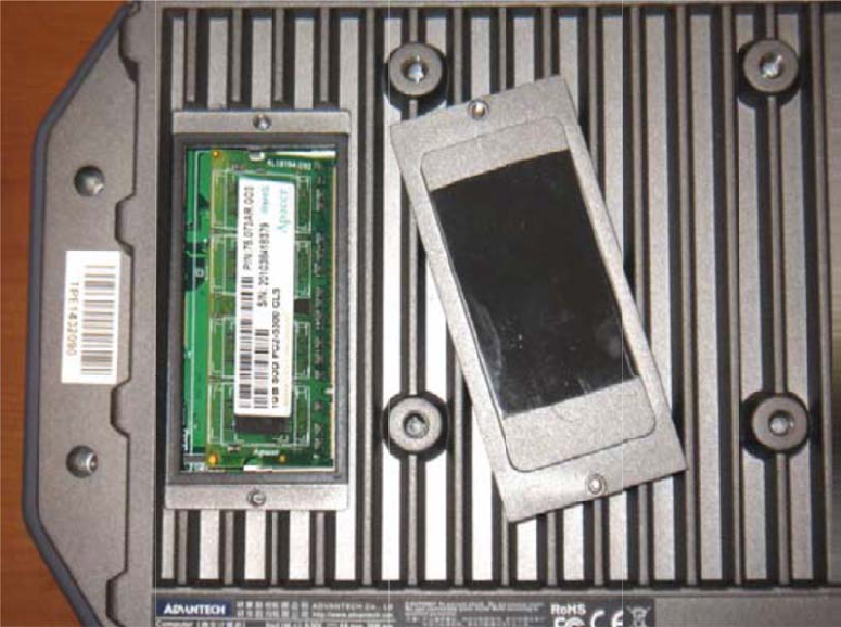
3.2 Installing the Storage Device and SIM Card
TREK-773 has a side door and a user can easily install a SIM card or storage (CFast
or SD) card. The CFast card is the main bootable storage card which has the
operating system pre-installed from Advantech. The CFast slot with an ejector (on the
top side) can eject the CFast card from the socket with a press. The SDcard acts as
secondary storage in TREK-773. The system is NOT allowed boot up from SD.
Note! Please do NOT paste any sticker or label on a CFast or SD card; it might
cause jamming and not be able to be ejected from the slot/socket.
Chapter 3 Hardware & Peripheral
Installation
SDCardCfastCard
SIM
3.
3
TR
E
be
o
we
s
da
m
No
t
RA
M
ba
c
bo
x)
3.
4
Op
t
for
p
typ
e
3
Inst
a
E
K-773 su
p
o
pened for
s
uggest thi
s
m
age(like el
t
e! For bes
t
M
door (Bl
o
c
k on. (For
a
x)
.
4
Inst
a
t
ional acce
s
p
urchase a
s
e
mounting
a
lling
S
p
ports 204-
p
RAM instal
l
s
change p
e
ectrostatic
t
thermal m
a
o
ck in black
)
a
bare bon
e
a
lling
O
s
sories, like
s
complem
e
with M5 ty
p
ystem
p
in SODIM
M
l
ation. It is
v
e
rformed b
y
d
ischarge
o
a
nagement
,
)
is always
i
e
system, t
h
O
ption
a
RAM mou
n
e
nts for TR
E
p
e screws
o
Mem
o
M
type DD
R
v
ery easy t
o
y
our servi
c
o
r memory
i
t
, please m
a
i
n place be
f
h
e thermal
p
a
l Acc
e
n
t kits or ot
h
EK-773. All
o
nly.
o
ry
R
3L DRAM.
o
open to i
n
c
e center to
i
nserted in
t
a
ke sure th
e
f
ore the do
o
p
ad is in th
e
e
ssori
e
h
er functio
n
accessori
e
There's a
d
stall memo
avoid any
p
t
he wrong
p
e
thermal p
a
o
r cover is
p
e
accessori
e
e
s
n
al module
s
e
s use stan
d
d
oor which
o
ry. Howev
e
p
ossible
p
osition.)
a
d on
p
ut
e
s
s
are availa
b
d
ard 75m
m
can
e
r,
b
le

3.5 Installing the I/O Cover
To ensure TREK-773’s entire system is protected with an IP54 rating, assemble the
IP54 I/O cover kit to mask all the connectors on the bottom side.
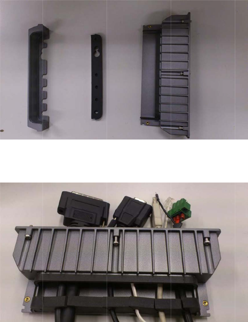
Fro
m
ad
h
I/O
and
C
h
In
Co
n
m
left to rig
h
esive cove
r
cover and
r
d
moving to
w
h
apte
stalla
t
n
nect all ca
b
ht: plastic I
/
r
on the ba
c
r
oute all ca
b
w
ard the in
s
r 3 H
a
t
ion
b
les to syst
/
O cover, r
u
c
k side of r
u
b
les across
s
ide.
a
rdwa
e
m and se
c
u
bber seal,
u
bber seal,
a
the plastic
re &
P
c
ure before
and plastic
a
dhere the
I/O box st
a
P
erip
h
the cover i
s
I/O box. R
e
a rubber s
e
a
rting from t
h
eral
s
installed.
e
move tap
e
e
al to the pl
a
t
he outside
e
a
stic
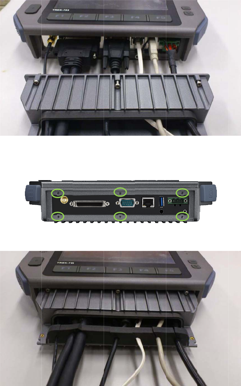
Th
e
mo
u
Ins
t
e
re are 6 sc
u
nting fram
e
t
all the cov
e
rews holes
e
needs to
e
r attaching
designed f
o
be secured
it in place
w
o
r the extr
a
by these h
w
ith the 6
s
a
mechanic
a
oles.
s
crews.
a
l part installation. The
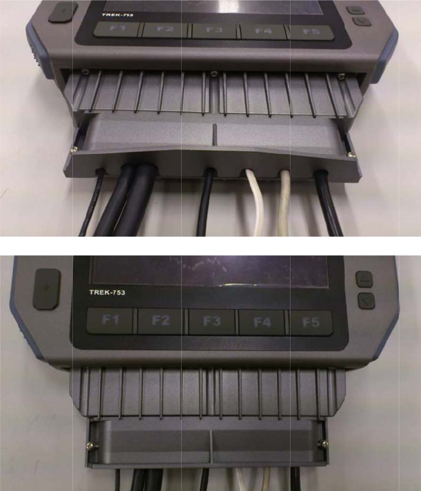
Scr
e
Ins
t
C
h
In
Se
e
e
w the pla
s
t
allation co
m
h
apte
stalla
t
e
the explo
d
s
tic I/O cov
e
m
plete.
r 3 H
a
t
ion
d
ed drawin
g
e
r onto the
p
a
rdwa
g
for clear a
p
lastic I/O
b
re &
P
a
ssembly ill
u
b
ox.
P
erip
h
u
stration.
h
eral
3.
6
TR
E
inst
a
co
m
use
ne
e
Blu
e
Wir
e
W
W
GP
S
No
t
or i
t
6
Inst
a
E
K-773 is a
all at once
a
m
es with T
R
rs will not
n
e
d to build
n
e
tooth
e
less LAN(
W
W
AN (LTE)
S
t
e! All hard
w
t
s authoriz
e
a
lling
W
highly inte
g
a
nd work b
y
R
EK-773, al
l
n
eed to set
t
n
ew wireles
s
W
LAN)
w
are or rec
o
e
d service
p
W
ireles
s
g
rated all-i
n
y
independ
e
l
wireless c
o
t
hem up ag
s
connectio
o
nfiguratio
n
artners.
s
Opti
o
n
-one termi
n
e
nt connec
t
o
nnections
ain. This in
o
ns if neces
s
n
changes
s
o
ns
n
al, all wire
t
ion. In the
have been
formation i
s
s
ary. RF o
p
s
hould be p
e
less option
s
s
tandard O
setup in a
d
s
provided
f
p
tions inclu
d
e
rformed b
y
s
are able t
O
S that
d
vance and
f
or those w
h
d
e:
y
Advantec
o
h
o
h
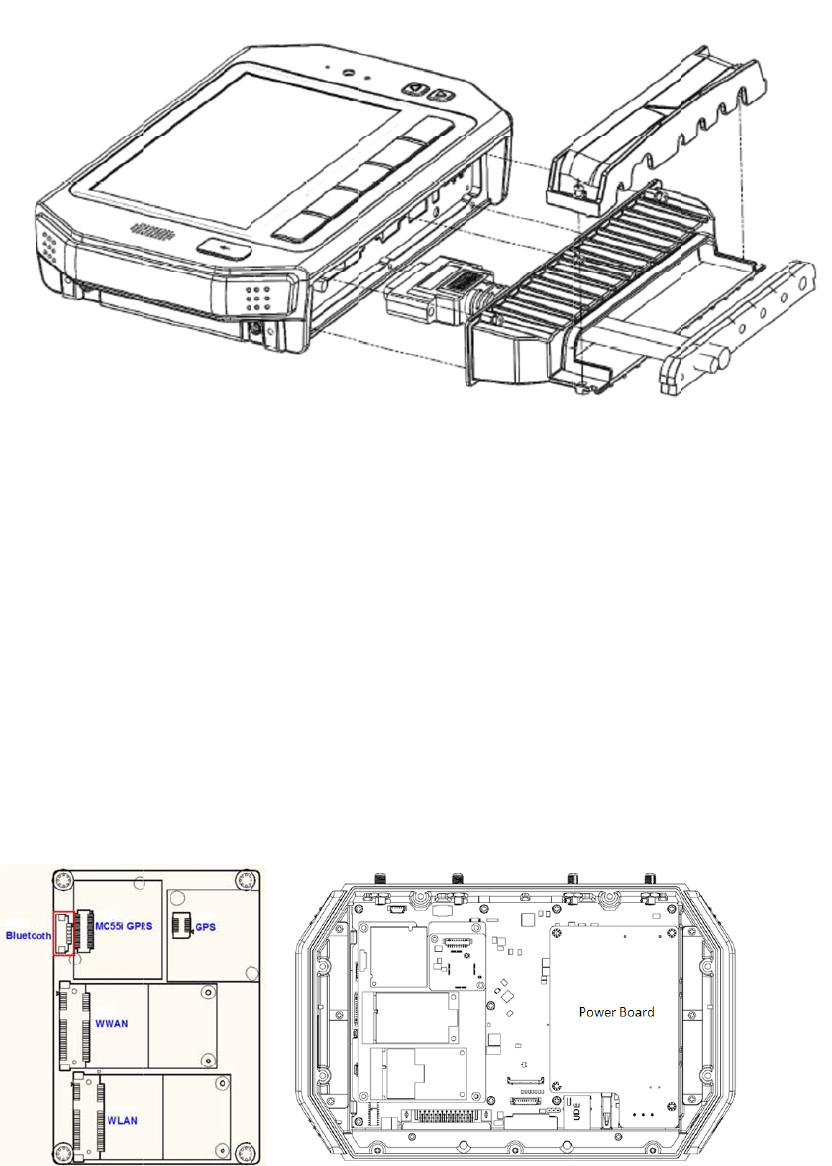
3.
6
Dri
v
1.
Fig
u
2.
M
TR
E
3.
T
4.
D
inst
a
Set
1.
P
and
Wir
e
6
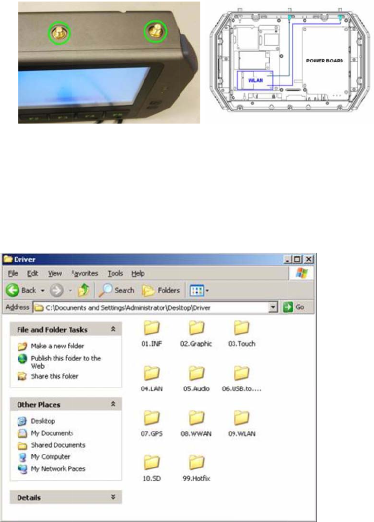
.1 WLA
N
v
er Install
a
Make sure
u
re 3.1 To
p
M
ake sure t
h
E
K-773 to
c
T
urn on the
D
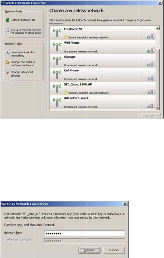
ouble clic
k
all drive
r
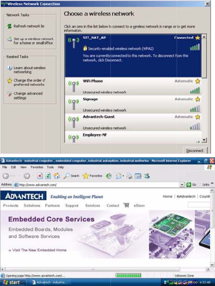
up Conne
c
P
ress Start
-
d
select pro
p
e
less Netw
o
N
a
tion
the Wi-Fi
m
p
View of
T
h
ere is a wi
c
onnect to.
TREK-773,
k
"Setup.ex
e
c
tion
-
Control p
a
p
erties for t
h
o
rks".
m
odule has
T
REK-773
reless rout
e
and boot i
n
e
" from the
d
a
nel - Netw
o
h
e wireless
been instal
e
r and acc
e
n
to the OS.
driver CD (
W
o
rk connec
t
s
network c
o
led in the
T
e
ss point w
o
W
LAN_A
W
t
ions - Pres
o
nnection;
c
T
REK-773.
o
rking avail
a
W
-NE768_0
9
s
right mou
c
lick "View
A
a
ble fo
r
9
0714) to
se button
A
vailable
C
h
In
2.
H
but
t
3.
S
(en
t
4.
C
Op
e
h
apte
stalla
t
H
ighlight on
e
t
on found i
n
S
ome APs
d
t
ering user
C
lick Conne
e
n the web
r 3 H
a
t
ion
e
of the av
a
n
the lower
r
d
evices will
ID & pass
w
ct after ent
e
browser a
n
a
rdwa
a
ilable wirel
r
ight-hand
c
have differ
e
w
ord if prom
e
ring key (i
f
n
d TREK-7
7
re &
P
ess LAN ic
o
c
orner.
e
nt SSIDs;
pted).
f
prompted
)
7
3 will conn
e
P
erip
h
o
ns and do
choose an
)
to connec
t
e
ct to the i
n
h
eral
uble click o
available o
n
t
to the wir
e
n
ternet.
o
n the Con
n
ne and con
e
less AP.
ect
nect
3.
6
Dri
v
1.
6
.2 LTE(
4
v
er Install
a
Make sure
4
G)
a
tion
the LTE m
o
o
dule has
b
b
een install
e
e
d in the T
R
R
EK-773.
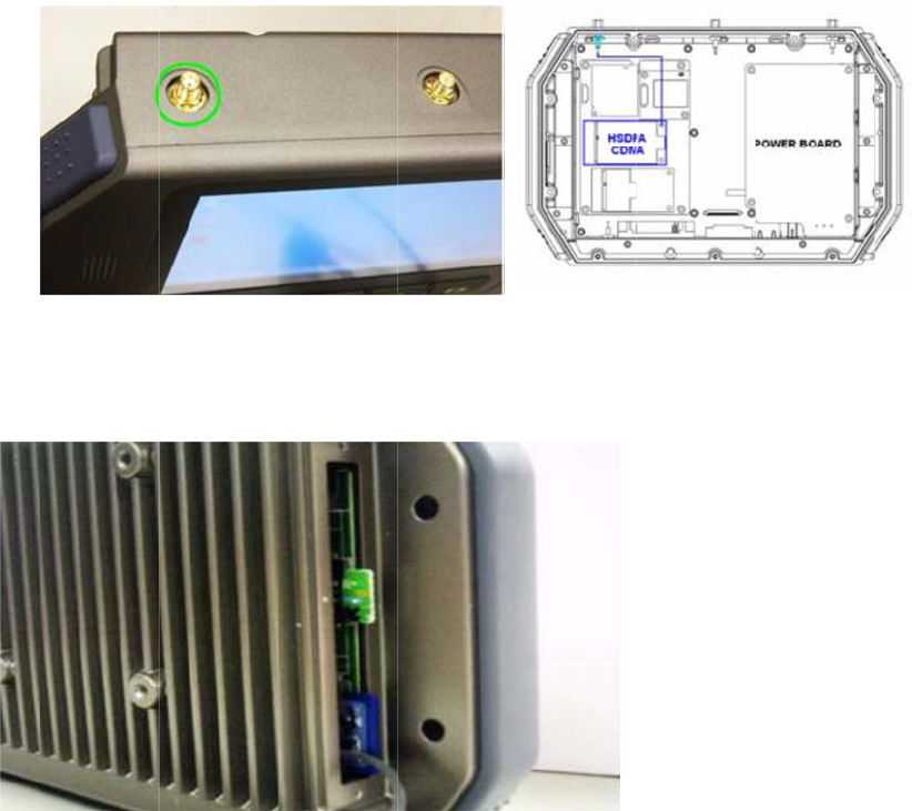
Fig
u
2. I
n
ap
p
C
h
In
3.
T
4. I
n
fro
m
u
re 3.3 To
p
n
sert the u
s
p
lied to a G
S
h
apte
stalla
t
T
urn on the
n
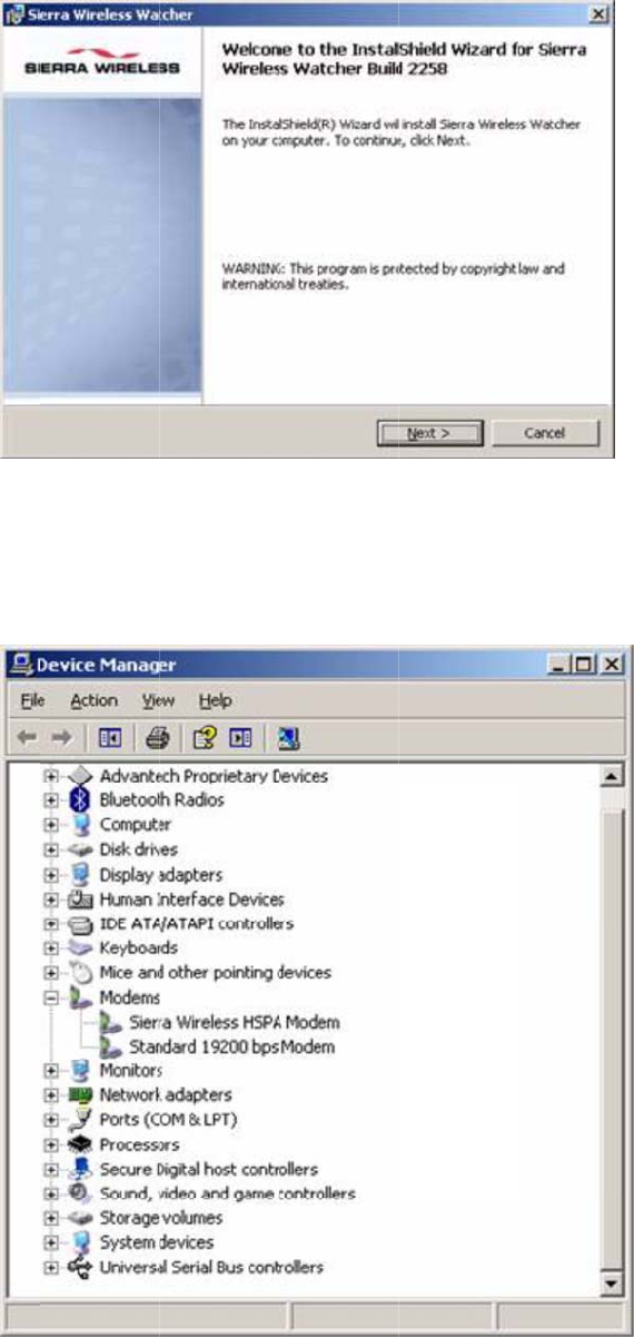
stall the H
S
m
driver CD
p
View of
T
s
er's SIM c
a
S
M networ
k
r 3 H
a
t
ion
TREK-773,
S
DPA US
B
on the Wi
n
T
REK-773
a
rd in the sl
o
k
in advanc
e
a
rdwa
then boot
i
B
module dr
i
n
dows Emb
e
ot; make s
u
e
and can t
r
re &
P
into the O
S
iver/AP "W
a
edded OS.
u
re the SIM
r
ansmit/rec
e
P
erip
h
.
a
tcher_Ge
n
card has a
e
ive data.
h
eral
n
eric Build
2
a
lready
2
258.msi"
Set
1.
C
ma
r
2.
T
con
3.
O
4.
D
up Conne
c
C
heck the d
r
ks.
T
o complet
e
nection to
m
O
nce compl
D
ouble Clic
k
c
tion
evice man
a
e
the new c
o
m
y desktop
eted, the n
e
k
the "Sierr
a
a
ger to ma
k
o
nnection
w
," then clic
k
e
w connect
a
Wireless
W
k
e sure ther
e
w
izard textb
k
“Finish.”
ion will be
c
W
atche
r
" a
n
e
are no e
n
ox, select "
A
c
reated.
n
d Click Bu
tries with q
A
dd a shor
t
tton "Conn
e
uestion
t
cut to this
e
ct." The
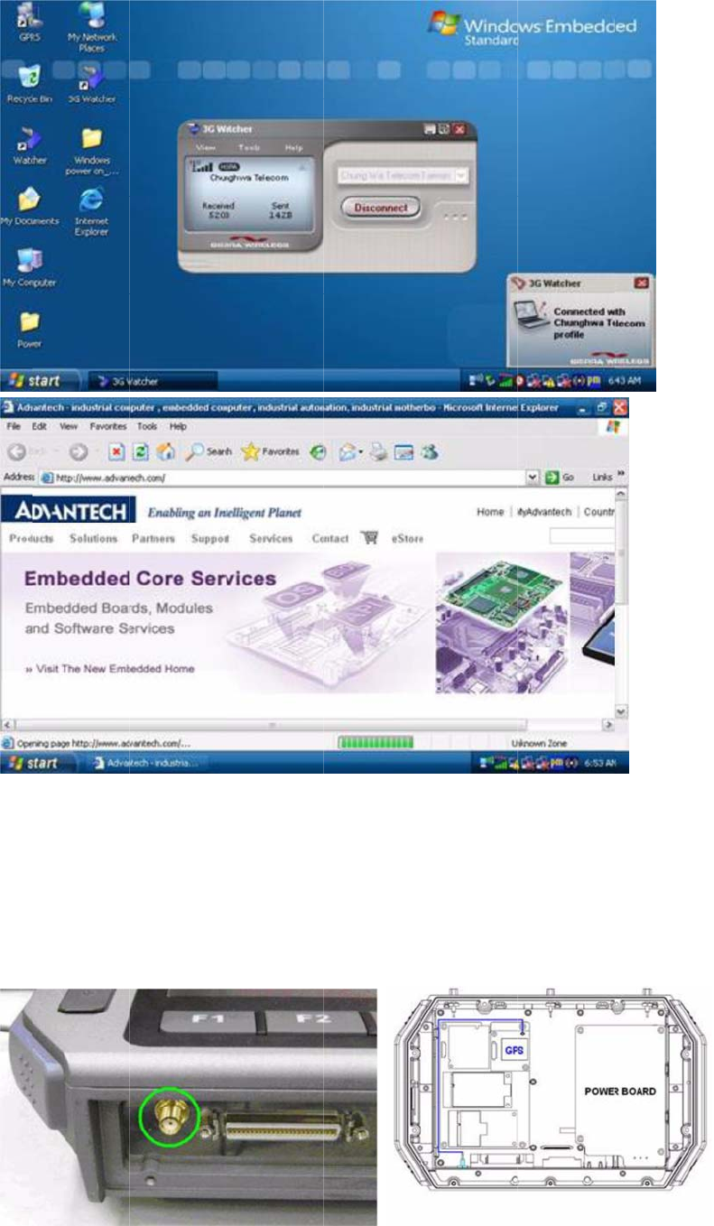
TR
E
3.
6
Ins
t
1.
M
77
3
E
K-773 will
6
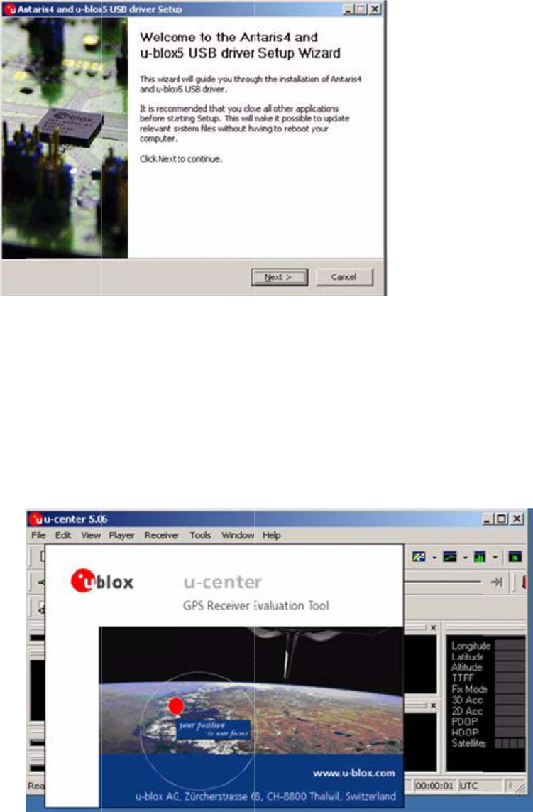
.3 GPS
t
allation
M
ake sure t
h
3
.
connect to
h
e GPS m
o
the interne
t
o
dule & ant
e
t.
e
nna has al
ready bee
n
n
installed i
n
n
the TRE
K
-
Fig
u
2.
T
3.
D
on
t
C
h
In
Set
1.
2.
S
for
G
u
re 3.4 Bo
t
T
urn on the
D
ouble clic
k
t
he driver
C
h
apte
stalla
t
up Conne
c
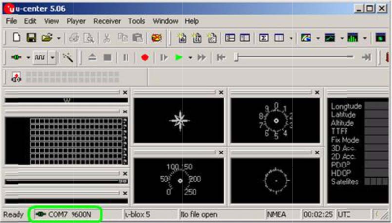
Install "u-C
S
tart test in
G
PS modu
l
t
tom View
TREK-773,
k
"ublox_A4
_
C
D to install
.
r 3 H
a
t
ion
c
tion
enter" to s
e
"u-Center,"
l
e.
of TREK-7
7
boot up th
e
_
U5_USB
_
.
a
rdwa
e
tup and te
s
setting C
O
7
3
e
OS.
_
drv3264_i
n
re &
P
s
t.
O
M port (C
O
n
stall_UI.ex
e
P
erip
h
O
M3) and b
a
e
" applicati
o
h
eral
a
ud rate (9
6
o
n progra
m
6
00bps) us
e
m
e
d
3.
A
Vie
w
A
fter startin
g
w
setup co
n
g
test, NM
E
n
nection.
E
A output m
essages a
r
r
e display i
n
n
the Devel
o
o
pment Da
t
t
a
C
4.
1
4.
2
Ta
b
C
hap
t
1
Rear
2
Pow
e
b
le 4.1: P
o
t
er
4
Side
C
e
r Con
o
wer Con
n
4
P
C
onne
c
necto
r
n
ector
P
in As
s
c
tors
r
s
ignm
e
e
nts
PI
1
3
No
t
IS
O
(O
p
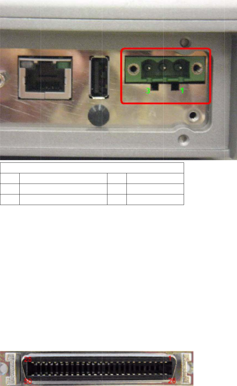
C
h
4.
3
Ta
b
N Signal
1
Ground
3
Acc Ig
n
t
e! TREK-7
Input Volta
g
O
7637-2 &
S
48 V optio
n
p
tional)
h
apte
3
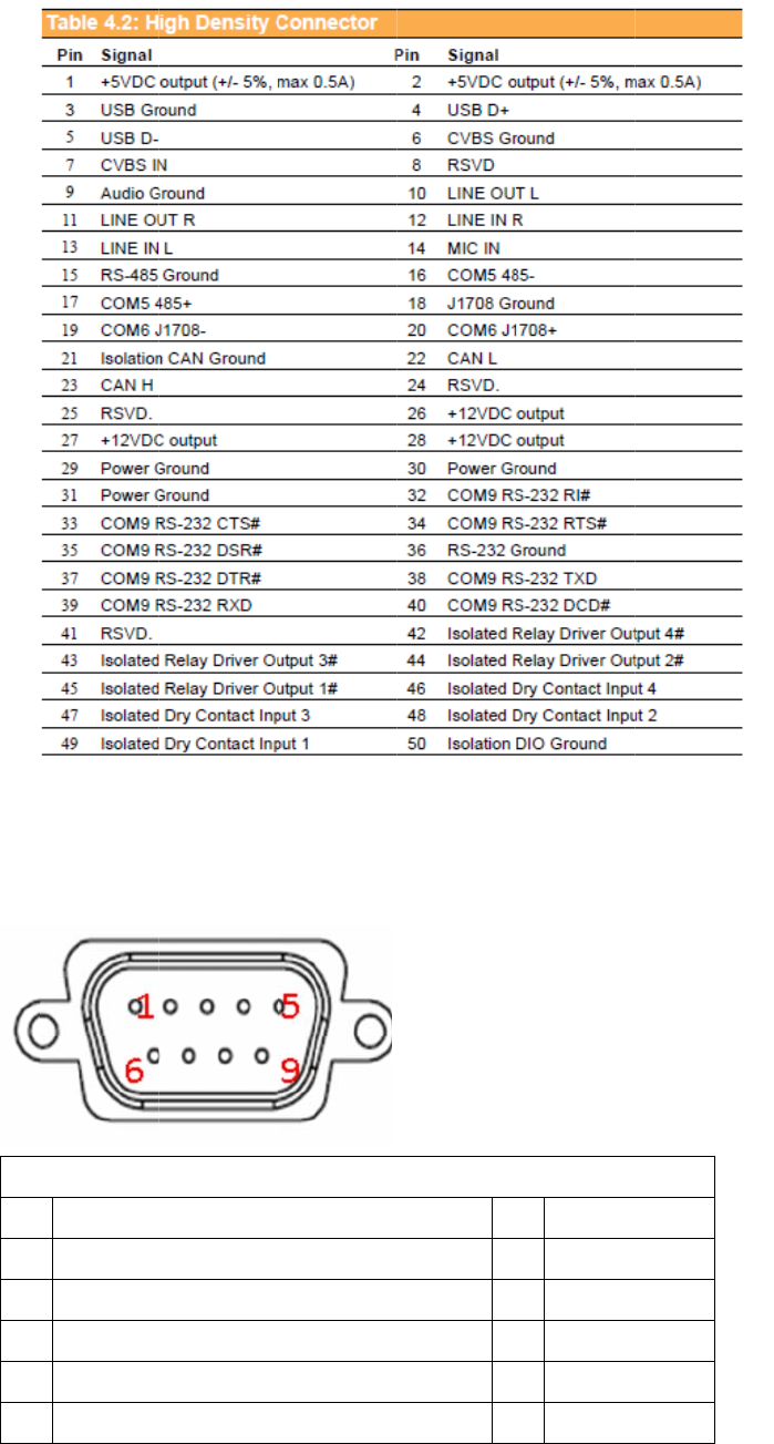
High
b
le 4.2: Hi
g
Table
n
ition Input
73 has 2 p
o
g
e 12 V/24
S
AE J1113
n
supports
1
r 4 Pi
n
Densi
t
g
h Densi
t
4.1: Power
C
o
wer option
s
V options
s
complianc
e
1
8~58 V in
p
n
Ass
i
t
y Con
t
y Conne
c
C
onnector
PIN Si
2 P
o
s for differ
e
s
upport 9~
3
e
(default)
p
ut for spec
i
ignm
e
n
necto
r
c
gnal
o
wer input
e
nt applicat
i
3
2 V
p
ower
i
fic applica
t
e
nts
r
o
ns:
d
esign wit
h
i
ons
t
h
t
or
4.
4
PI
N
1
3
5
7
9
4
RS-2
N
Signal
RS-232 D
C
RS-232 T
X
RS-232 G
r
RS-232 R
T
RS-232 R
I
32 Co
n
Table 4.3:
R
C
D
X
D
r
ound
T
S
I
/ +12 VD
C
n
necto
R
S-232 Con
C
(max. 250
0
r (CO
M
n
nector (CO
M
P
I
2
4
6
8
0
M
9)
M
8)
I
N Signal
2
RS-232
R
4
RS-232
D
6
RS-232
D
8
RS-232
C
R
XD
D
TR
D
SR
C
TS

4.
5
Thi
s
Thi
s
Wh
e
Ta
b
mA)
5
LED
s
system p
o
s
LED will
b
e
n system
i
b
le 4.3: R
S
Indica
t
o
wer indica
t
b
e lit on wh
e
i
s off, this L
S
-232 Co
n
t
or
t
or is an or
a
e
n the syst
e
ED will not
nector (C
a
nge LED,
c
e
m is in N
O
be lit.
OM8)
c
ontrolled
b
O
RMAL mo
d
b
y hardwar
e
d
e.
e
.

Chapter 5 Software Demo Utility Setup
5.1 Introduction
AdvantechhasdevelopeddemoutilitiesbasedonAdvantechprovidedSDKAPIsto
letusertestthefunctionsonTREK‐773.Thisdocumentdescribestheusageofeach
demoutilitiesandalsoprovideabasicconceptoftheapplicationdevelopmenton
TREK‐773.
Fortechnicalsupport,contactAdvantechapplicationengineersworldwide.Fornews
updates,visitourwebsite:www.advantech.com
5.2 IVCP Demonstration
TheIVCPdemonstrationapplicationdemonstratetheusageofMRMIVCPAPIwhich
isalightweightinterfacebetweenOS(Operatingsystem)andIVCP(IntelligentVehicle
Co‐Processor)allowusertoaccessthestatusofmachineandchangemachine
behaviorsuchaspowermanagement,bootbehavior,peripheralcontroletc.
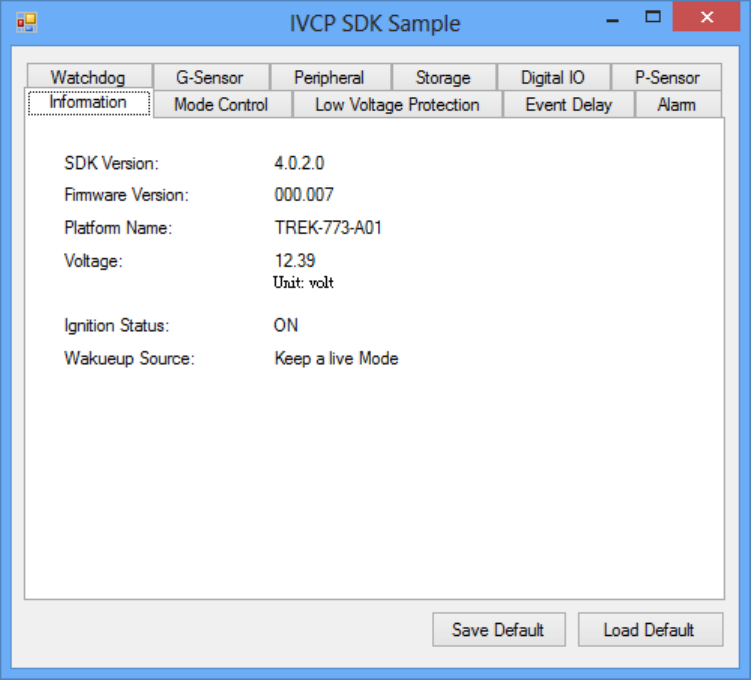
5.2.1 Information
Inthispage,thedemoapplicationshowsthecurrentstatusandbasicinformation.
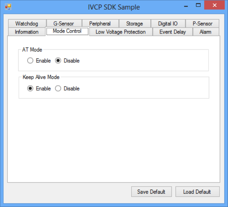
5.2.2 Mode Control
Inthispage,youcantoggle“ATMode”and“KeepAliveMode”.
Press“SaveDefault”tosetcurrentsettingsasdefaultvalueofVPM(VehiclePower
Management)controller.
Press“LoadDefault”toloadthedefaultvalues.
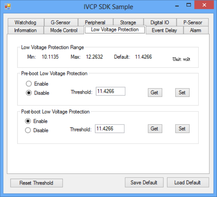
5.2.3 Low Voltage Protection
Youcanenable/disableandsetthepre‐boot/post‐bootlowvoltageprotection
thresholdinthispage.
Press“Get”togetthecurrentthresholdvalueandPress“Set”tosetthevalue.
Press“SaveDefault”tosetcurrentvalueasdefaultvalueofVPMcontroller.
Press“LoadDefault”toloadthestoreddefaultvalues.
5.
2
TR
E
req
u
The
The
an
O
(ON
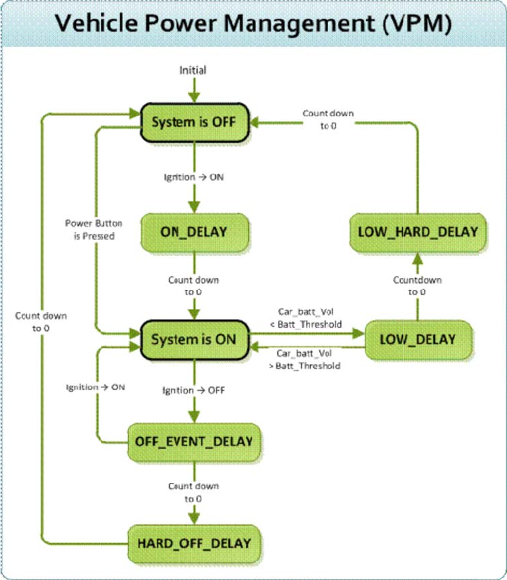
2
.4 Even
t
5.2.4.
1
E
K773prov
i
u
irements.
powerofsy
IgnitionO
N
ignitionsig
n
O
FFstatean
d
_DELAY).O
n
t
Delay
1
Pow
e
i
desVPM(
V
Thebasic
m
stemcanbe
N
n
alcanbeus
d
theignitio
n
n
ceitcounts
e
rcont
r
V
ehiclePo
w
m
echanism
controlled
w
edtopowe
r
n
isturned
O
tozero,the
r
olme
c
w
erManag
e
isshownin
w
iththefoll
o
r
onorshut
d
O
N,theVPM
systemwill
b
c
hanis
m
e
ment)feat
u
thefollow
i
o
wingevent
s
d
ownthesys
t
controller
w
b
epowered
m
u
restofulfi
ngfigure.
s
:
t
em.When
t
w
illcountdo
w
on.
llspecific
t
hesystemi
s
w
nadelayp
e
s
in
e
riod
IgnitionOFF
Whenthesystemispoweredonandtheignitionisturnedoff,theVPMcontrollerwill
countdownadelayperiod(OFF_EVENT_DELAY).Duringthisperiod,iftheignition
isswitchedbacktoON,theVPMcontrollerwillstopcountdownandresetthe
OFF_EVENT_DELAY.IfOFF_EVENT_DELAYcountstozero,theVPMcontrollerwilltriggeran
poweroffevent(i.e.powerbuttonpress).Systemandapplicationswhichreceivesthis
eventcandopre‐definedtasks,likestoringdataandpreparingtoturnoffthesystem.
Aftertheeventistriggered,VPMcontrollerstartstocountdownnextdelayperiod
(HARD_OFF_DELAY).IfHARD_OFF_DELAYcountstozero,thesystempowerwillbecutoff
abruptlytoavoidunexpectedsystemhang.Aldo,onceVPMcontrollerenterthe
HARD_OFF_DELAYstage,theprocesscannotbereversed.
Lowpowerprotection
Toavoiddrainingpower,low‐powerprotectionistoensurethatthereisenoughpower
tostartthemachine.WhenthesystemisON,theVPMcontrollerwillmonitorthepower
voltage.Ifthevoltageislowerthantheprogrammablethreshold(LOW_THRESHOLD),the
VPMcontrollerwillstarttocountdownadelay(LOW_DELAY).Duringthestageof
LOW_DELAYcountdown,ifvoltage
goesbackaboveLOW_THRESHOLD,theVPMcontrollerwillstopcounting
downandexit.
IfLOW_DELAYcountstozero,theVPMcontrollerwilltriggeranpoweroffevent(i.e.power
buttonpress)andstartstocountdownnextdelayperiod(LOW_HARD_DELAY).IfLOW_
HARD_DELAYcountstozero,thesystempowerwillbecutoffabruptlytoavoiddrainingthe
power.
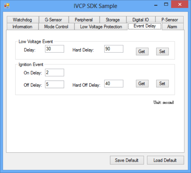
5.2.4.2 Demonstration
Youcansetthedelayandharddelaytimeofthelowvoltageeventandignition
event.
LowVoltageEvent
Delay:
ThedelaytimebeforeVPMtriggerapoweroffevent(i.e.powerbuttonpress).
HardDelay:
Thedelaytimecounteddownafterapoweroffeventistriggered.VPMwill
forcepoweroffthemachineiftheharddelaytimeiscounteddowntozero.
IgnitionEvent
OnDelay:
ThedelaytimebeforeVPMtriggeranpoweronevent(poweronthemachine).
OffDelay:
ThedelaytimebeforeVPMtriggeranpoweroffevent(i.e.powerbuttonpress).
HardOffDelay:
Thedelaytimecountedafteranpoweroffeventistriggered.VPMwillforce
poweroffthemachineiftheharddelaytimeiscounteddowntozero.
Press“SaveDefault”tosetcurrentvalueasdefaultvalue.
Press“LoadDefault”toloadthestoreddefaultvalues.
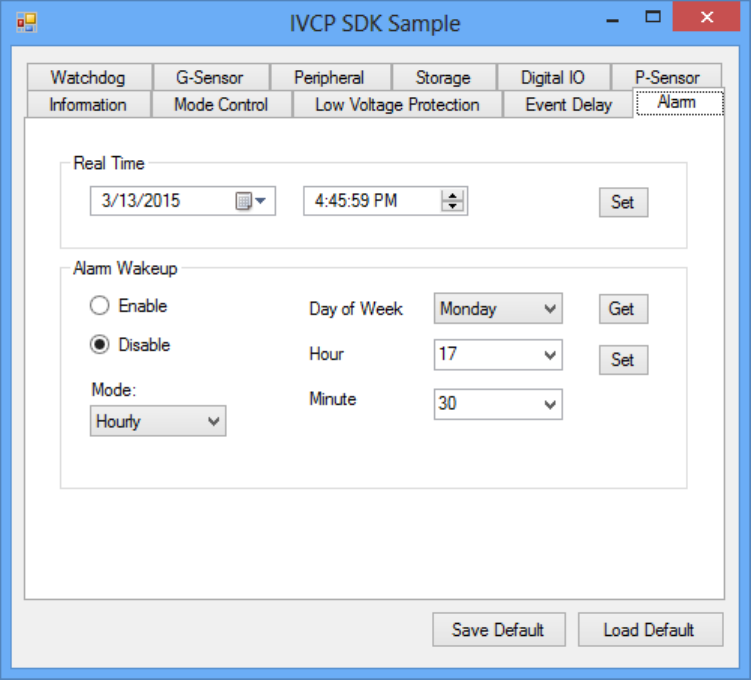
5.2.5 Alarm
Inthispage,youcansetthetimeandsetalarmwakeuptimetoVPMcontrollerand
enable/disablethealarmasasystemwakeupsource.
Press“SaveDefault”tosetcurrentvalueasdefaultvalue.
Press“LoadDefault”toloadthestoreddefaultvalues.
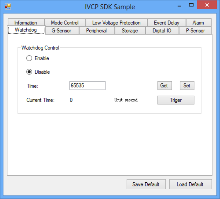
5.2.6 Watchdog
Inthispage,youcanenable/disablethewatchdogfunctionandsetthecounttime
(second)forthewatchdogtoavoidunexpectedsystemhang..
Whenwatchdogisenabled,theVPMcontrollerwillstartcountingdownthetimeset
forwatchdogandpoweroffthemachineifitiscountedto0.Youcanpress“Trigger”
buttonwhilewatchdogiscountingtoresetthecountdowntimeandkeepit
counting.
Press“SaveDefault”tosetcurrentvalueasdefaultvalue.
Press“LoadDefault”toloadthestoreddefaultvalues.
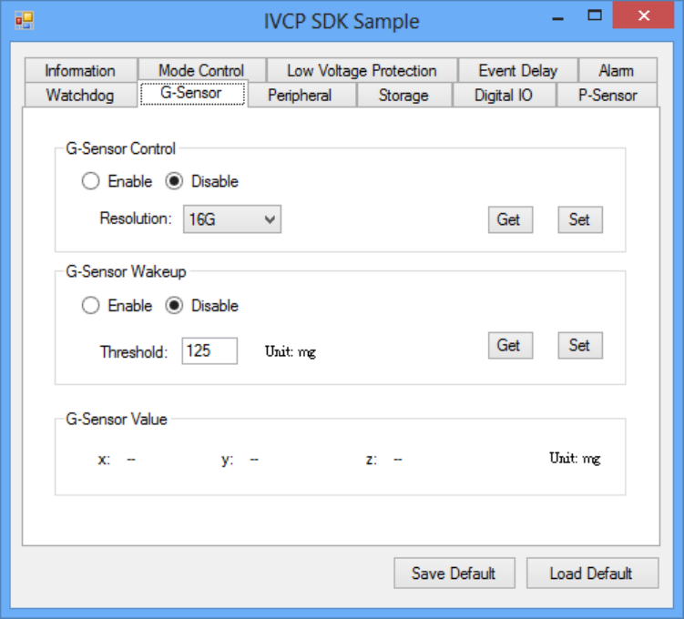
5.2.7 G-Sensor
Inthispage,youcanenable/disabletheG‐sensor.Also,youcansetG‐sensorasa
systemwakeupsourceandsetthethresholdtotriggersystemwakeup.
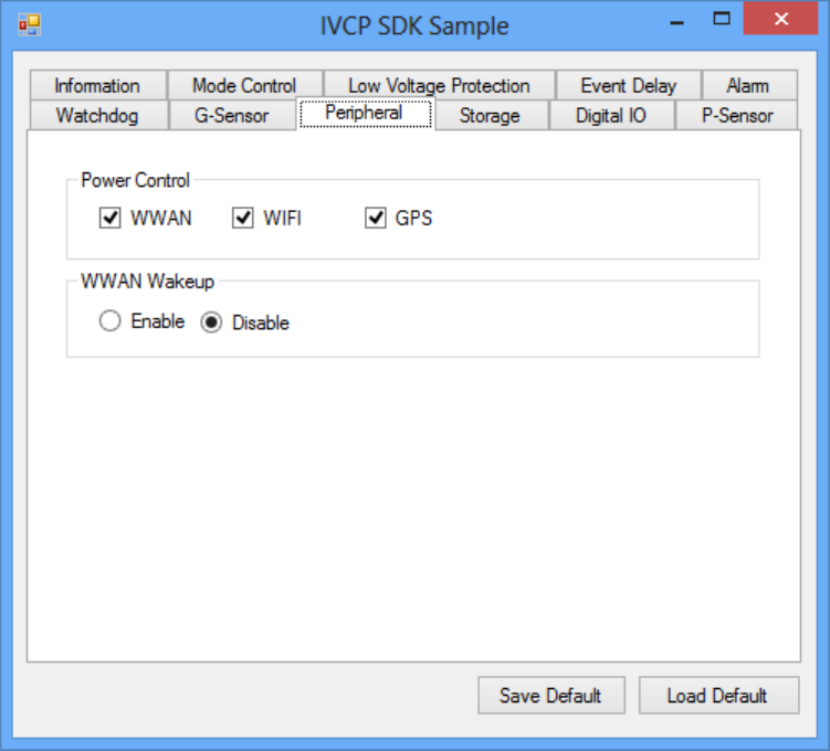
5.2.8 Peripheral
Inthispage,youcanenable/disabletheperipheralfunctionsandsetWWANas
systemwakeupsource.
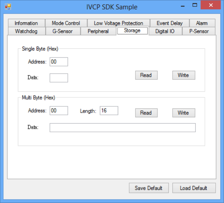
5.2.9 Storage
Inthispage,youcansave/loadarbitrarydatatotheprivatestorage(256byte)onthe
machine.
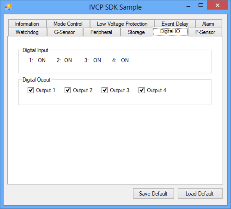
5.2.10 Digital IO
Inthispage,youcanmonitorthedigitalinputstatusandenable/disabledigital
output.
DI1defaultisnormaldigitalinputandcanbesetasdedicatedreversesignalinput.
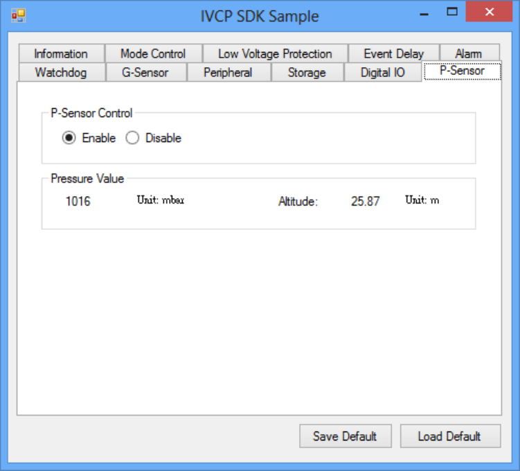
5.2.11 P-sensor
Inthispage,youcanmonitorthep‐sensorstatusandenable/disableit.
5.3 VCIL Demonstration
TheVCILdemonstrationapplicationdemonstratetheusageofMRMVCIL(Vehicle
CommunicationInterfaceLayer)APIwhichallowusertoaccessvehicleprotocol
easily.
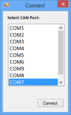
5.3.1 Port selection
WhenfirstopenVCILdemonstrationapp,youwillseeaportselectionwindowsas
following.
PleaseselecttheVCILportpathandpressConnectbutton.
VCILportpathindifferentplatformshavedifferentnodes.Thecommonpathat
WindowisCOM7.
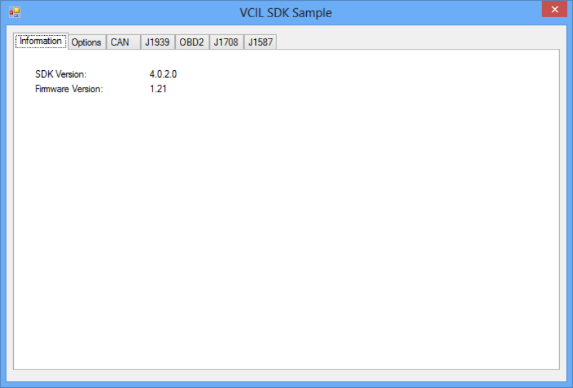
5.3.2 Information
Inthispage,thedemoapplicationshowsthecurrentstatusandbasicinformation.
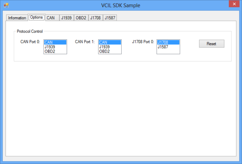
5.3.3 Option
Inthispage,youcanthesettheprotocolforeachport.
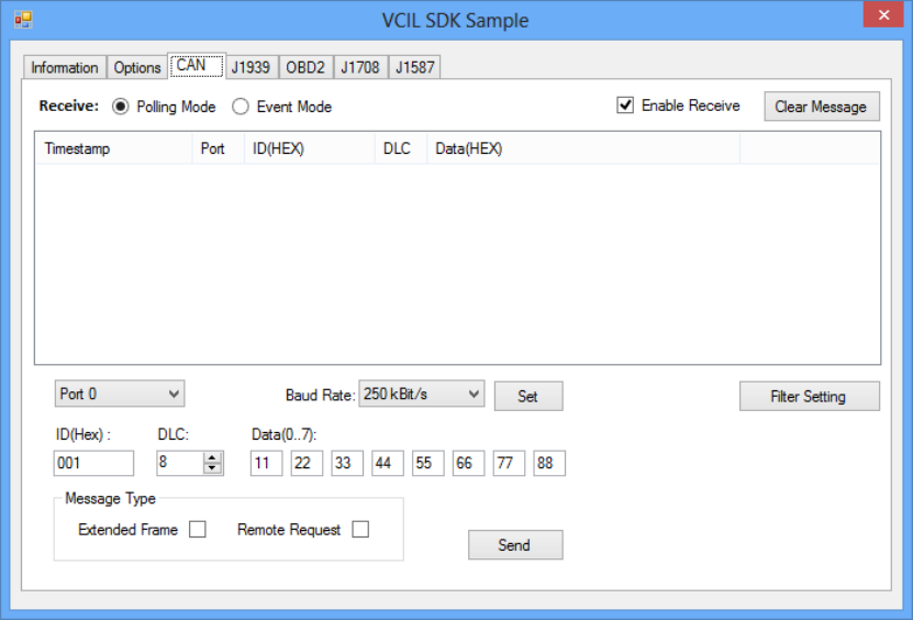
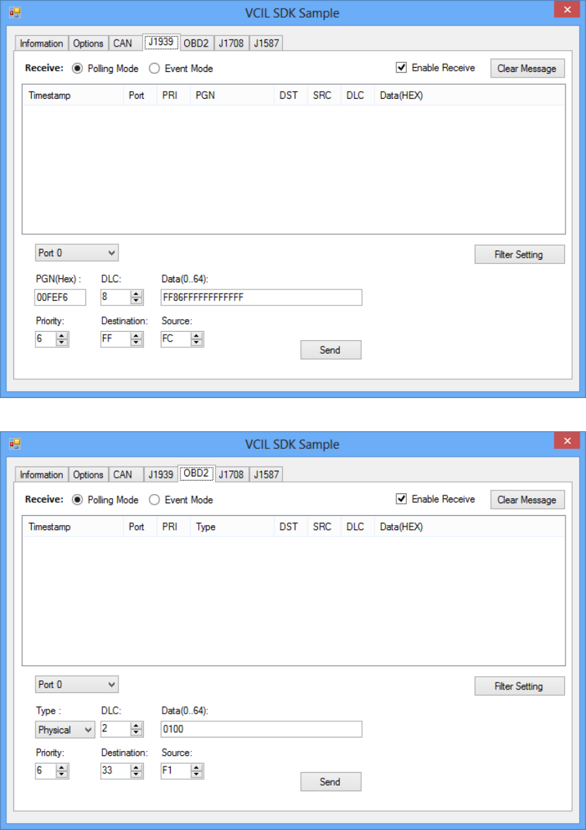
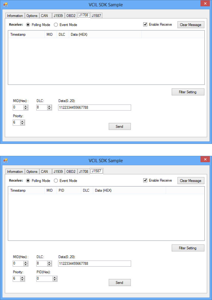
5.3.4 CAN / J1939 / OBD2 / J1708 / J1587
TouseCAN/J1939/OBD2/J1708/J1587protocoloneachport,pleaseclickon
correspondingtabtoswitchtothepageofspecificprotocol,thenyoucansend/read
messageonspecificportbysettingthedetailitems.
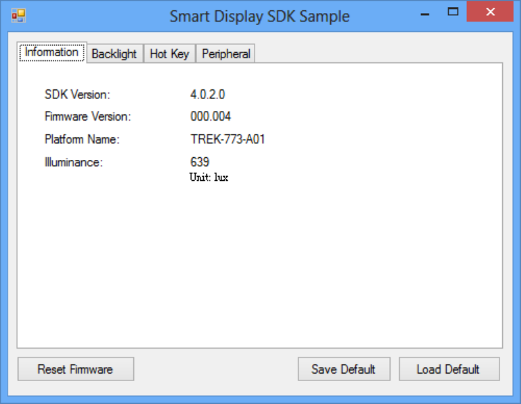
5.4 Smart Display Demonstration
ThesmartdisplaydemonstrationapplicationdemonstratetheusageofMRMSDPAPI
whichisalightweightinterfacebetweenOS(Operatingsystem)andSDP(Smart
DisplayCo‐Processor)allowusertocontrolthefont‐enddisplay,backlightsetting,
hotkey,peripheralcontrol,etc.
5.4.1 Information
Inthispage,thedemoapplicationshowsthecurrentstatusandbasicinformation.
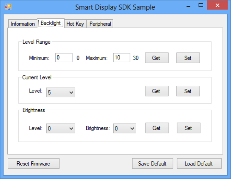
5.4.2 Backlight
Inthispage,youcansetthelevelsforbacklight,thebrightnessforeachlevelandthe
currentbrightnesslevel.
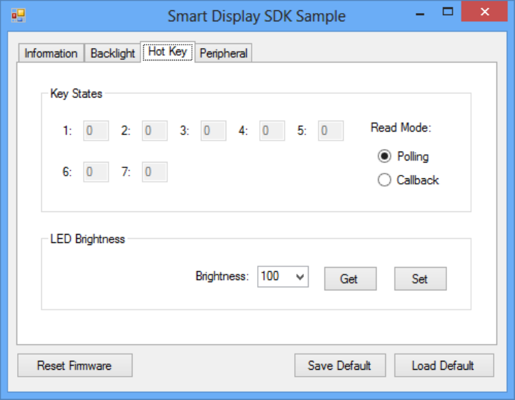
5.4.3 Hot key
Inthispage,youcanmonitorthepressstateofeachhotkeyandsettheLED
brightnessofthehotkeys.
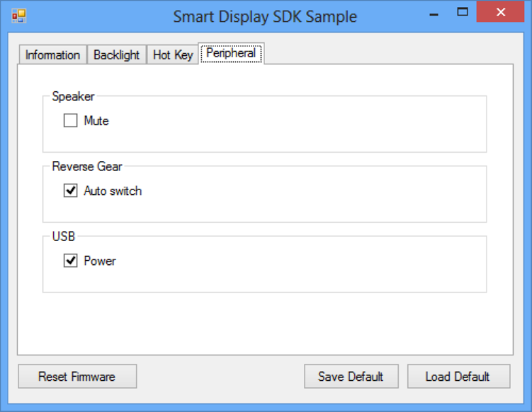
5.4.4 Peripheral
Inthispage,youcancontrolthestatusofperipheraldevices.
Speaker
Enable/disablespeakervolume.
Reservegear
Enable/disableautoswitchofdisplay.Ifenabled,thedisplaywillbeswitchedto
cameraviewifreversegeardetectedandswitchedtoLVDSviewifreversegear
absent.
USB
Enable/disablepoweroffront‐endUSBport.
5.5 GPS Demonstration
TheGPSdemonstrationapplicationdemonstratetheusageofMRMGPSAPIwhichis
alightweightinterfacebetweenOS(Operatingsystem)andGPSmoduleallowsuser
toeasilygetGPSinformation.
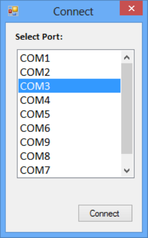
5.5.1 Port selection
WhenfirstopenGPSdemonstrationapp,youwillseeaportselectionwindowsas
following.
PleaseselecttheGPSportpathandpressConnectbutton.Thecommonpathat
WindowisCOM3.
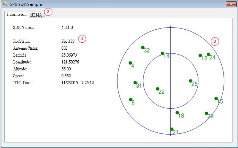
5.5.2 Information
Inthispage,thedemoapplicationshowsthecurrentGPSstatus.
1. GPSStatus
2. Functiondemonstrationselection
3. SatellitelocationInformation
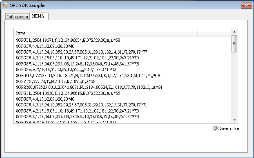
5.5.3 NEMA
Inthispage,thedemoapplicationshowstheincomingNMEAcode.Check'Saveto
file'tologgingtheNMEAcodetofile.
Appendix A
AHigh Density Cable Pin
Assignment
The high density connected for TREK-773 includes 48 wires in a 2-meter cable. It
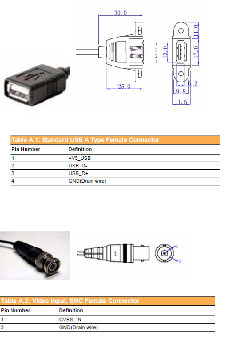
extends functionality of many of the I/O port with standard type connectors.
At the host side, a 3M 10150-3000 PE series 50-pin connector can be connected with
TREK-773.
A.
A.
Ta
b
Ta
b
A
p
1 Stan
2 Vide
b
le A.1: S
t
b
le A.2: Vi
p
pen
d
dard
U
o inpu
t
t
andard U
deo Inpu
t
d
ix A
H
U
SB A
T
t
, BNC
S
B A Typ
e
t
, BNC Fe
m
H
igh
D
T
ype F
C
Fema
e
Female
m
ale Con
n
D
ensit
emale
le Con
Connect
o
n
ector
y Ca
b
Conn
e
necto
r
o
r
b
le Pi
n
e
ctor
r
n

A
s
A.
A.
Ta
b
s
sign
m
3 RS-
2
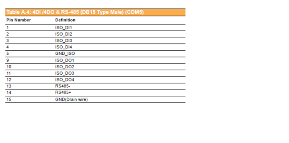
4 4DI /
b
le A.3: R
S
m
ent
2
32 Co
n
4DO
&
S
-232 Co
n
n
nect
o
&
RS-4
8
n
nector (
D
o
r (DB
9
8
5 (DB
1
D
B9) (CO
M
9
Male)
1
5 Typ
e
M
9)
(COM
e
Male
)
9)
) (CO
M
M
5)
A.
5.
0
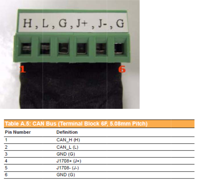
5 CAN
0
8mm
Bus
&
pitch)
&
J170
8
8
(Ter
m
m
inal B
lock 6
P
P
,
A.
3
P
Ta
b
A
p
A
s
6 Pow
e
P
, 5.08
m
b
le A.5: C
A
p
pen
d
s
sign
m
e
r Ext
e
m
m pit
c
A
N Bus (
T
d
ix A
H
m
ent
e
nsion
c
h)
T
erminal
B
H
igh
D
Conn
e
B
lock 6P,
5
D
ensit
e
ctor (
T
5
.08mm
P
y Ca
b
T
ermi
n
itch)
b
le Pi
n
n
al Blo
c
n
c
k

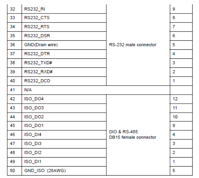
A.7 High Density & Connector Pin List
A
B
E
W
Fi
l
B.
1.
O
1.
A.
E
fun
c
to r
e
No
t
A
ppe
W
F (E
n
l
ter) M
a
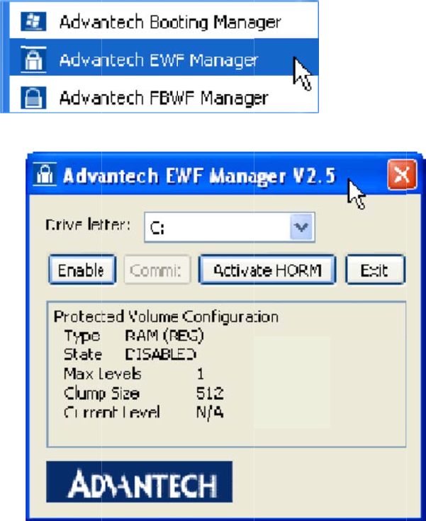
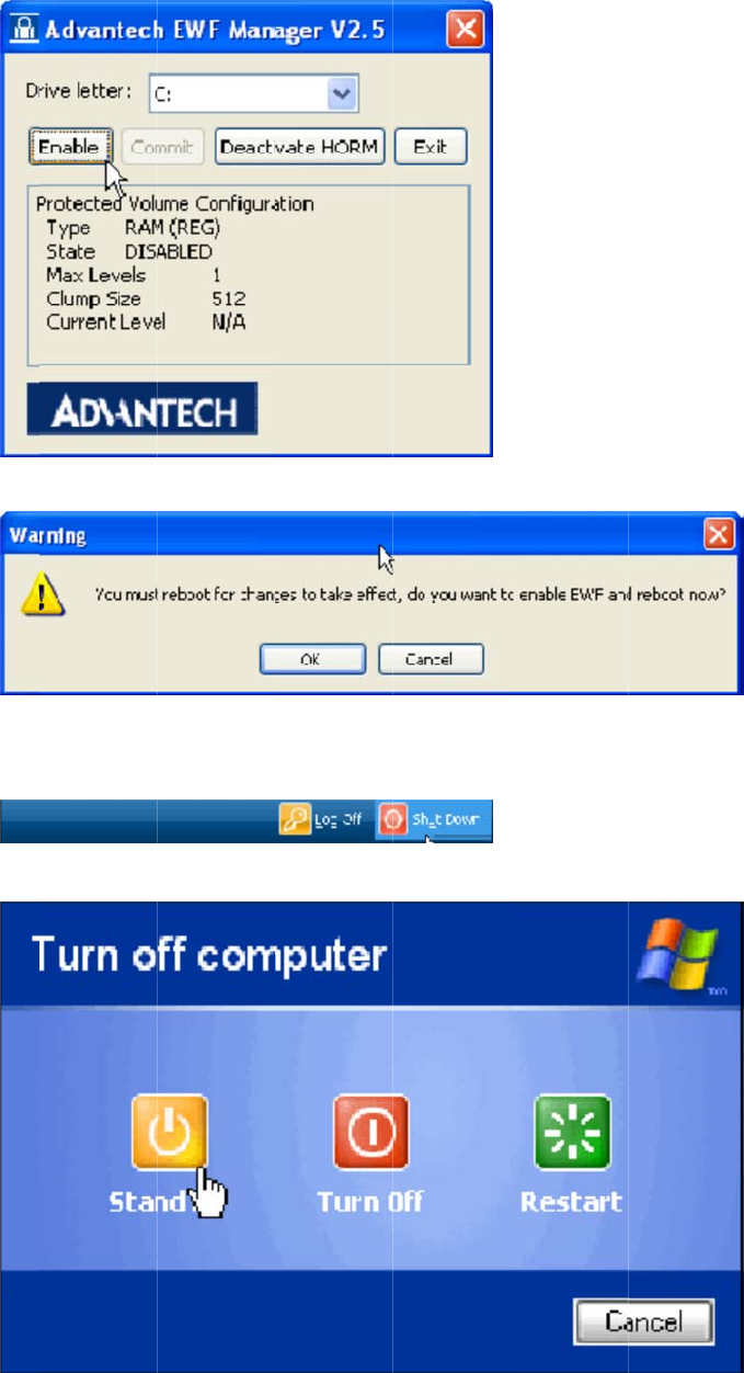
1 EW
F
O
pen Start
-
The followi
E
WF functi
c
tion
e
cover you
r
t
e! Please
c
ndi
x
n
hanc
e
a
nage
r
F
(Enh
a
-
> All Progr
a
ng input sc
r
on: If you
w
r
OS after
a
c
heck "C" v
o
x
B
e
d Writ
r
SOP
a
nced
W
a
ms -> Ad
v
r
een will b
e
w
ant to pro
t
a
restart..
o
lume is n
o
B
e
W
rite
F
v
antech ->
A
e
shown.
t
ect your o
p
o
t protecte
d
F
ilter)
M
A
dvantech
E
p
erating sy
s
d
.
M
anag
e
E
WF Mana
g
tem you ca
e
r SO
P
g
er.
a
n use the
P
E
W
1.
No
t
A
p
M
2.
3. I
f
mo
d
No
t
writ
HO
R
OS
W
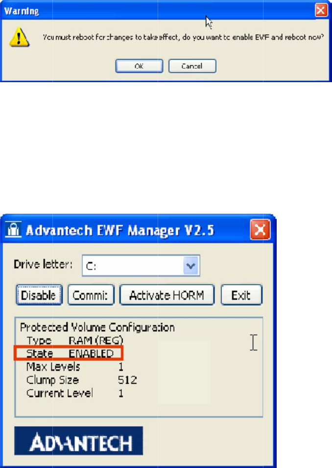
F Enable
M
Click Enab
t
e! Please
c
p
pen
d
anag
e
A
fter resta
r
f
you try to
c
d
ify data u
n
t
e! If you w
a
t
e data und
e
R
M (Hiber
n
after hiber
n
M
ethod:
le and a re
b
c
heck "C" v
o
d
ix B
E
e
r SO
r
t EWF stat
e
c
reate a fol
d
n
der the C
v
a
nt to write
e
r C volum
e
n
ate Once
n
ation, eve
n
b
oot the sy
s
o
lume is n
o
E
WF
(
P
e
will be se
t
d
er or file a
v
olume.
data at E
W
e
.
a
nd Resu
m
n
after a sh
u
s
tem when
o
t protecte
d
(
Enha
t
to "Enabl
e
a
nd restart t
W
F enable s
m
e Many):
T
u
tdown or
c
prompted.
d
.
nced
e
"
he OS, you
t
ate you ca
n
T
he functio
c
rash.
W
rite
will discov
e
n
click Co
m
n can alwa
y
Filter
er you can'
t
m
mit to
y
s resume
y
)
t
y
ou
r
I B
e
II C
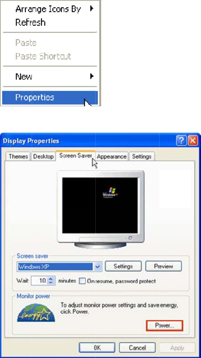
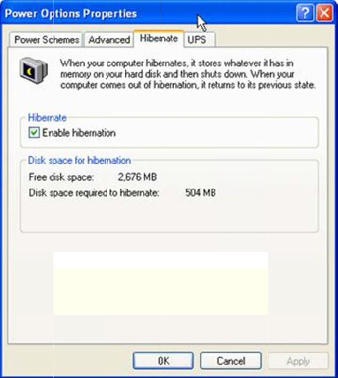
1.
2.
3.
e
fore using
heck "Ena
b
Right-Click
Choose "S
c
Check "En
a
HORM you
b
le hibernat
e
on deskto
p
c
reen Sav
e
a
ble hibern
a
should set
e
"
p
and click
"
e
r" panel an
a
te."
EWF to th
e
"
Properties
"
d click "Po
w
e
state "dis
a
"
w
er.”
a
ble"
A
p
M
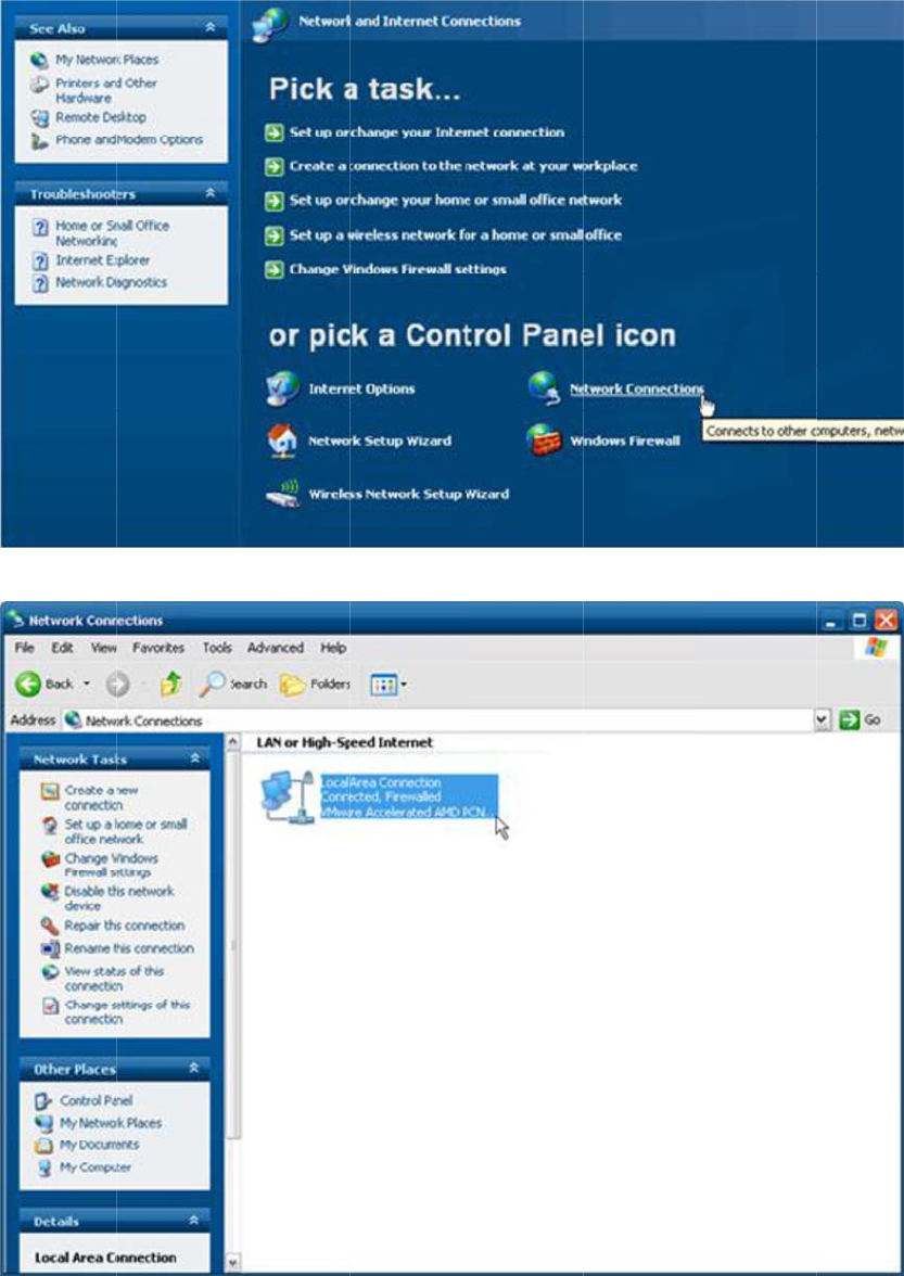
III
A
1.
O
2.
C
p
pen
d
anag
e
A
ctivate HO
O
pen Start
-
C
lick "Activ
a
d
ix B
E
e
r SO
RM
-
> All Progr
a
a
te HORM.
"
E
WF
(
P
a
ms -> Ad
v
"
(
Enha
v
antech ->
A
nced
A
dvantech
E
W
rite
E
WF Mana
g
Filter
g
er.
)
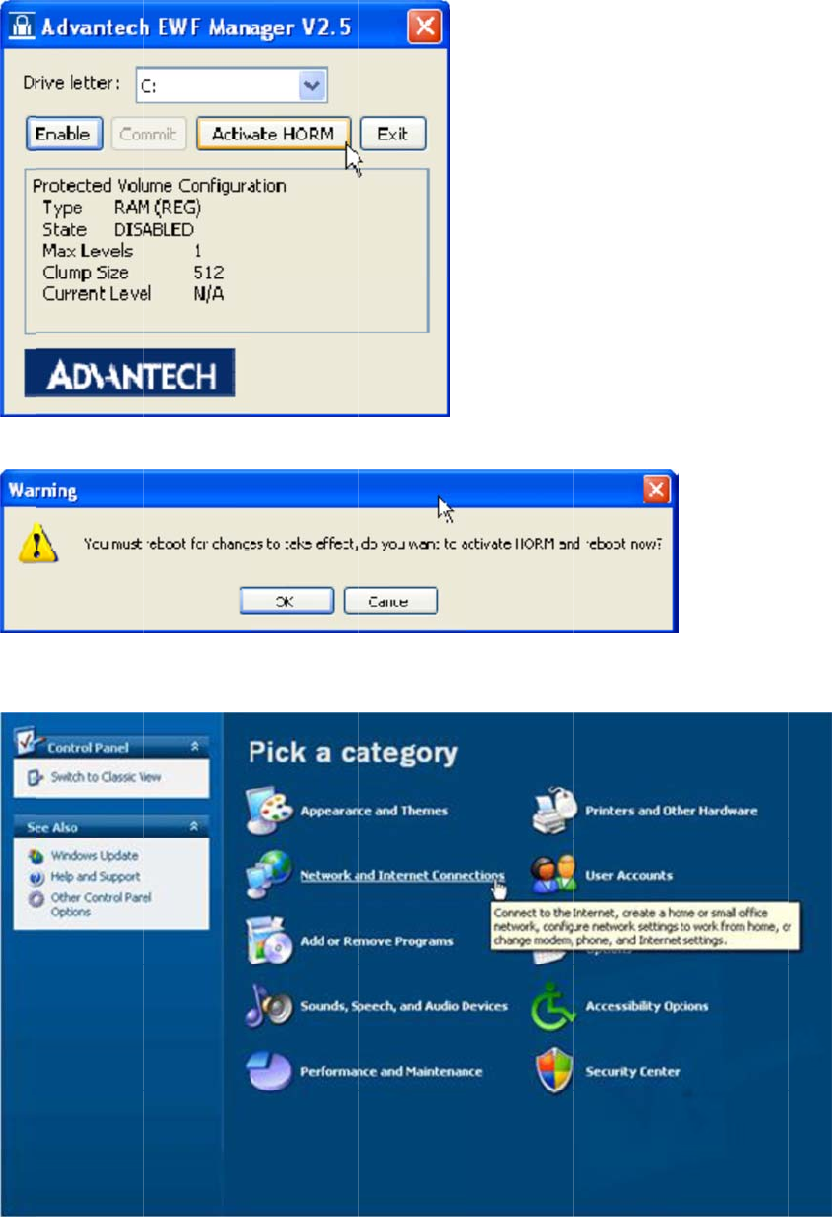
3.
C
IV
C
1.
2.
C
hick "OK"
t
C
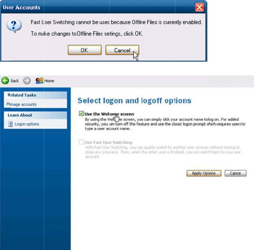
heck "Use
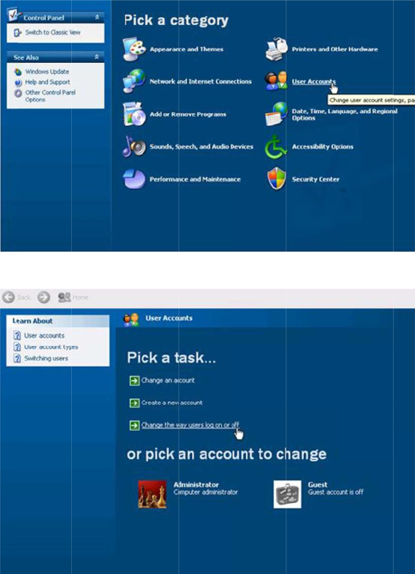
Open Start
Click "Net
w
t
o reboot O
the Welco
m
-> Control
w
ork and In
t
S
.
m
e screen.
"
Panel.
t
ernet Con
n
"
n
ections."
3.
A
p
M
Click "Net
w
p
pen
d
anag
e
w
ork Conne
d
ix B
E
e
r SO
c
tion."
E
WF
(
P
(
Enhanced
W
rite Filter
)
4.
5.
6.
C
7.
O
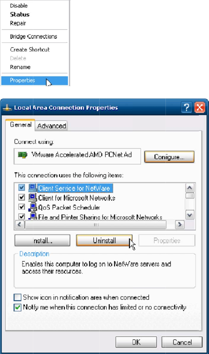
Right-Click
Uninstall "
C
C
lick "Yes"
t
O
pen Start
-
on "Local
A
C
lient Servi
c
t
o remove "
-
> Control
P
A
rea Conn
e
c
e for Net
W
Client Serv
P
anel.
e
ction" and
W
are."
ice for Net
W
click prope
W
are" and
r
r
ties.
r
eboot OS.
8.
C
9.
C
C
lick "User
A
C
lick "Canc
e
A
ccounts"
e
l."
10.
63
T
A
p
M
V E
1.
O
2.
C
Check "Us
e
T
REK-753 U
s
p
pen
d
anag
e
nable EW
F
O
pen Start
-
C
lick "Enabl
e
the Welc
o
s
er Manual
d
ix B
E
e
r SO
F
-
> All Progr
a
e."
o
me screen
E
WF
(
P
a
ms -> Ad
v
n
" and Click
(
Enha
v
antech ->
A
"Apply Op
t
nced
A
dvantech
E
ions"
W
rite
E
WF Mana
g
Filter
g
er.
)
3.
C
VI
R
1.
O
2.
W
C
lick "OK" t
o
R
un "Hiber
n
O
pen Start
-
W
hen you p
o
reboot O
S
n
ate"
-
> Shut Do
w
ress "Shift"
S
.
w
n
the Stand
b
b
y icon will
b
b
e replace
d
d
with a Hib
e
ernate ico
n
.
TR
E
VII
E
VIII
con
65
T
A
p
M
E
K-753 User
E
nable HO
R
If you unpl
u
tinue its re
s
T
REK-753 U
s
p
pen
d
anag
e
Manual 64
R
M is finis
h
u
g power c
o
s
ume state.
s
er Manual
d
ix B
E
e
r SO
h
ed.
o
rd after re
s
E
WF
(
P
s
uming sy
s
(
Enha
s
tem, you w
nced
ill discover
W
rite
the OS will
Filter)