Advantech Co UTC520FPIKA0E Computer User Manual V4 12 EV User Manual
Advantech Co Ltd Computer V4 12 EV User Manual
User manual
User Manual
UTC-520FP-IKA0E
21.5”
Ubiquitous Touch Computer

UTC-520 User Manual ii
Copyright
The documentation and the software included with this product are copyrighted 2018
by Advantech Co., Ltd. All rights are reserved. Advantech Co., Ltd. reserves the right
to improve the products described in this manual at any time without notice. No part
of this manual may be reproduced, copied, translated, or transmitted in any form or
by any means without the prior written permission of Advantech Co., Ltd. The infor-
mation provided in this manual is intended to be accurate and reliable. However,
Advantech Co., Ltd. assumes no responsibility for its use, nor for any infringements
of the rights of third parties that may result from its use.
Acknowledgements
Award is a trademark of Award Software International, Inc.
AMD is a trademark of Advanced Micro Devices.
Corning Gorilla is a trademark of Corning Inc.
Intel, Atom, Celeron, and Core are trademarks of Intel Corp.
IBM, PC/AT, PS/2 and VGA are trademarks of International Business Machines Cor-
poration.
Microsoft Windows is a registered trademark of Microsoft Corp.
RTL is a trademark of Realtek Semiconductor Co., Ltd.
All other product names or trademarks are properties of their respective owners.
For more information about this or other Advantech products, please visit our website at
http://www.advantech.com
For technical support and service, please visit our support website at
http://support.advantech.com
This manual is for UTC-520FP-IKA0E.
Part No. 2008050050 Edition 2
Printed in Taiwan February 2018

iii UTC-520 User Manual
Declaration of Conformity
FCC Class B
15.19
This device complies with Part 15 of the FCC Rules. Operation is subject to the
following two conditions: (1) this device may not cause harmful interference, and
(2) this device must accept any interference received, including interference that
may cause undesired operation.
15.105
This equipment has been tested and found to comply with the limits for a Class B dig-
ital device, pursuant to part 15 of the FCC Rules. These limits are designed to pro-
vide reasonable protection against harmful interference in a residential installation.
This equipment generates, uses and can radiate radio frequency energy and, if not
installed and used in accordance with the instructions, may cause harmful interfer-
ence to radio communications. However, there is no guarantee that interference will
not occur in a particular installation. If this equipment does cause harmful interfer-
ence to radio or television reception, which can be determined by turning the equip-
ment off and on, the user is encouraged to try to correct the interference by one or
more of the following measures:
–Reorient or relocate the receiving antenna.
–Increase the separation between the equipment and receiver.
–Connect the equipment into an outlet on a circuit different from that to which
the receiver is connected.
–Consult the dealer or an experienced radio/TV technician for help.
15.21
Any changes or modifications not expressly approved by the party responsible
for compliance could void the authority to operate equipment.
This device and its antenna must not be co-located or operating in conjunction
with any other antenna or transmitter.
End-users and installers must be provided with antenna installation instructions
and transmitter operating conditions for satisfying RF exposure compliance.
For product available in the USA/Canada market, only channel 1~11 can be
operated. Selection of other channels is not possible
FCC RF Radiation Exposure Statement:
Mobile Device
This equipment complies with FCC radiation exposure limits set forth for an uncon-
trolled environment. This equipment should be installed and operated with minimum
distance 20cm between the radiator & your body.
Packing List
Before installing the UTC system, check that the following materials have been
included in the shipment:
UTC-520FP-IKA0E unit
Accessories for UTC-520FP-IKA0E
–DC 12V/7A 84W adaptor
If any of these items are missing or damaged, contact your distributor or sales repre-
sentative immediately.

UTC-520 User Manual iv
Technical Support and Assistance
1. Visit the Advantech website at http://support.advantech.com to obtain the latest
product information.
2. Contact your distributor, sales representative, or Advantech's customer service
center for technical support if you need additional assistance. Please have the
following information ready before calling:
–Product name and serial number
–Description of your peripheral attachments
–Description of your software (operating system, version, application software,
etc.)
–A complete description of the problem
–The exact wording of any error messages
Warnings
Contact information
Manufacturer
Advantech Co., Ltd.
No.1, Alley 20, Lane 26, Rueiguang Road Neihu District, Taipei, Taiwan 114, R.O.C.
TEL: (02) 2792-7818
EU Distributor
Advantech-DLoG
DLoG GmbH
Industriestr. 15
82110 Germering
Germany
Tel.: +49-89-411191-0
Industriestraße 15 82110 Germering
Warning! Batteries are at risk of exploding if incorrectly installed. Replace only
with the same or equivalent type recommended by the manufacturer.
Dispose of used batteries according to the manufacturer's instructions.
Warning!
Input voltage rated 12V/7A (UTC-520FP-IKA0E)
Use a 3V/195mA lithium battery
Packing: The unit should be carried with both hands and handled
with care.
Maintenance: Use only approved products or a dry applicator to
clean and maintain the surfaces.
CompactFlash: Turn off the system power before inserting or
removing the CompactFlash storage card.

v UTC-520 User Manual
Safety Instructions
1. Read these safety instructions carefully.
2. Retain this user manual for future reference.
3. Disconnect the equipment from all AC outlets before cleaning. Use only a damp
cloth for cleaning. Do not use liquid or spray detergents.
4. For pluggable equipment, the power outlet socket must be located near the
equipment and easily accessible.
5. Protect the equipment from humidity.
6. Place the equipment on a reliable surface during installation. Dropping or letting
the equipment fall may cause damage.
7. The openings of the enclosure are for air convection. Protect the equipment
from overheating. Do not cover the openings.
8. Ensure that the voltage is correct before connecting the equipment to a power
outlet.
9. Position the power cord away from high-traffic areas. Do not place anything over
the power cord.
10. All cautions and warnings on the equipment should be noted.
11. If unused for a long time, disconnect the equipment from the power source to
avoid damage from transient overvoltage.
12. Never pour liquid into an opening. This may cause fire or electrical shock.
13. Never open the equipment. For safety reasons, the equipment should be
opened only by qualified service personnel.
14. If one of the following occurs, have the equipment checked by authorized ser-
vice personnel:
The power cord or plug is damaged.
Liquid has penetrated the equipment.
The equipment has been exposed to moisture.
The equipment is malfunctioning or does not operate according to the user
manual.
The equipment has been dropped and damaged.
The equipment shows obvious signs of breakage.
15. Do not store the equipment in an environment where the temperature fluctuates
below -20 °C (-4 °F) or above 60 °C (140 °F) as this may cause damage. The
equipment should be stored in a controlled environment.
16. Batteries are at risk of exploding if incorrectly installed. Replace only with the
same or equivalent type recommended by the manufacturer. Discard used bat-
teries according to the manufacturer’s instructions.
17. Use only the recommended mounting apparatus to avoid damage due to falling.
18. The sound pressure level at the operator position does not exceed 70 dB (A) in
accordance with the IEC 704-1:1982.
DISCLAIMER: These instructions are provided according to IEC 704-1 standards.
Advantech disclaims all responsibility for the accuracy of any statements contained
herein.

UTC-520 User Manual vi
Warning! Because of the risk of electric shock, do not remove the equipment
cover during operation or when connected to a power outlet.
Caution! To avoid short circuits and otherwise damaging the device, do not allow
fluids to come in contact with the device. If fluids are accidentally spilled
on the equipment, remove the affected unit from service as soon as pos-
sible and contact service personnel to verify that personal safety is not
compromised. If the computer clock is unable to maintain accurate time
or the BIOS configuration resets to default, check the battery.
Caution! Do not replace the battery yourself. Contact a qualified technician or
your retailer. The computer is equipped with a battery-powered real-time
clock circuit. There is a danger of explosion if the battery is incorrectly
replaced. Replace only with same or equivalent type recommended by
the manufacturer. Discard used batteries according to the manufac-
turer’s instructions.

vii UTC-520 User Manual
Contents
Chapter 1 General Information ............................1
1.1 Introduction ............................................................................................... 2
1.2 Specifications ............................................................................................ 2
1.3 Dimensions ............................................................................................... 3
1.3.1 UTC-520FP-IKA0E ....................................................................... 3
Chapter 2 System Setup.......................................5
2.1 Quick Start Tour ........................................................................................ 6
2.1.1 Front View..................................................................................... 6
2.1.2 Rear View ..................................................................................... 6
2.1.3 Side View ...................................................................................... 7
2.2 I/O Ports .................................................................................................... 8
2.2.1 UTC-520FP-IKA0E ....................................................................... 8
2.3 Setup Procedures ..................................................................................... 8
2.3.1 System Power On ......................................................................... 8
2.3.2 BIOS Setup ................................................................................... 8
2.3.3 System Software Installation......................................................... 9
2.3.4 Driver Installation .......................................................................... 9
Chapter 3 Upgrades and Installation.................11
3.1 Introduction ............................................................................................. 12
3.2 Installing Peripherals (Optional) .............................................................. 13
3.2.1 UTC-520FP-IKA0E ..................................................................... 13

UTC-520 User Manual viii

Chapter 1
1General Information

UTC-520 User Manual 2
1.1 Introduction
Advantech's UTC-520FP-IKA0E is a fanless, low-power, all-in-one touch panel com-
puters suitable for use as control room computing devices, production line industrial
digital signage, showroom interactive signage, self-service kiosks, and public service
terminals, as well as to support diverse digital retail, hospitality, healthcare, educa-
tion, entertainment, and information processing applications. Featuring a protective
enclosure, advanced touchscreen technology, wireless capabilities, and rich I/O, the
high-performance UTC series can also be integrated with a wide range of optional
peripherals and accessories according to specific application requirements.
1.2 Specifications
System
CPU Intel® Core™ i5-6300U
(UTC-520FP-IKA0EF)
Base
Frequency 2.6GHz (dual-core)
Cache L3 cache 4 MB
Memory 2 x SODIMM DDR3L 1600 MHz,
up to 16 GB
HDD
1 x 2.5 internal SATA HDD bay
Network (LAN) 2 x Gigabit Ethernet ports
(with Wake-on-LAN support)
I/O
2 x RS-232 COM (RS-422/485 optional)
3 x USB 2.0/2 x USB 3.0
2 x Gigabit Ethernet (RJ-45)
1 x VGA/HDMI
1 x Audio Line-Out
1 x Mic-In
1 x USB for Bottom Peripheral
Stereo Speaker 2 x 3W
Bus
Expansion 1 x Full-size mini PCIe/mSATA
Mounting VESA VESA 100 x 100 mm
Dimensions
(W x H x D) 517.64 x 313.51 x 43.50 mm
Weight 8 kg (17.6 lb)
OS Support Windows Embedded 7/8, Windows 10 IoT Enter-
prise
Environmental
Operating Temperature 0 ~ 40 °C (32 ~ 104 °F)
Relative Humidity 10 ~ 95% @ 40 °C non-condensing
Vibration 0.5 Grms
Shock 5 G peak acceleration (11 msec. duration)
EMC/Safety CE, FCC, UL, CCC CB,BSMI
Front Panel Protection IP65/NEMA4 compliant
Power Supply
Input Rating 12 V/7 A (84W ITE adapter)
Power
Consumption
Typical 40W
Max. 50W
3 UTC-520 User Manual
Chapter 1 General Information
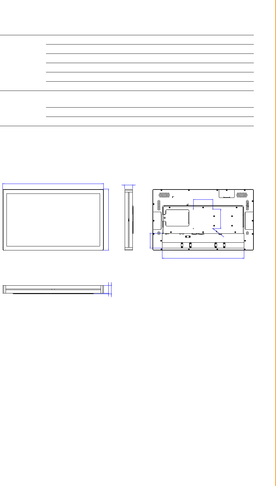
1.3 Dimensions
1.3.1 UTC-520FP-IKA0E
LCD Panel
Size/Type 21.5" TFT LCD with LED backlight
Max.Resolution 1920 x 1080
Max. Color 16.7M
Pixel Pitch (H x V) 248.25 x 248.25 um
Brightness 250 cd/m2 (400 cd/m2 optional)
Viewing Angle 178°/178°
Touchscreen
(PE/RE/GE)
Type Glass panel with projected capacitive/5-wire ana-
log resistive touch
Light Transmission 90% ± 2% / 80% ± 5% / 90%
Controller USB interface
517.64
313.51
40
420
75.36
100
100
VESA Holes M4
depth 5mm max
40
43.50

UTC-520 User Manual 4

Chapter 2
2System Setup
UTC-520 User Manual 6
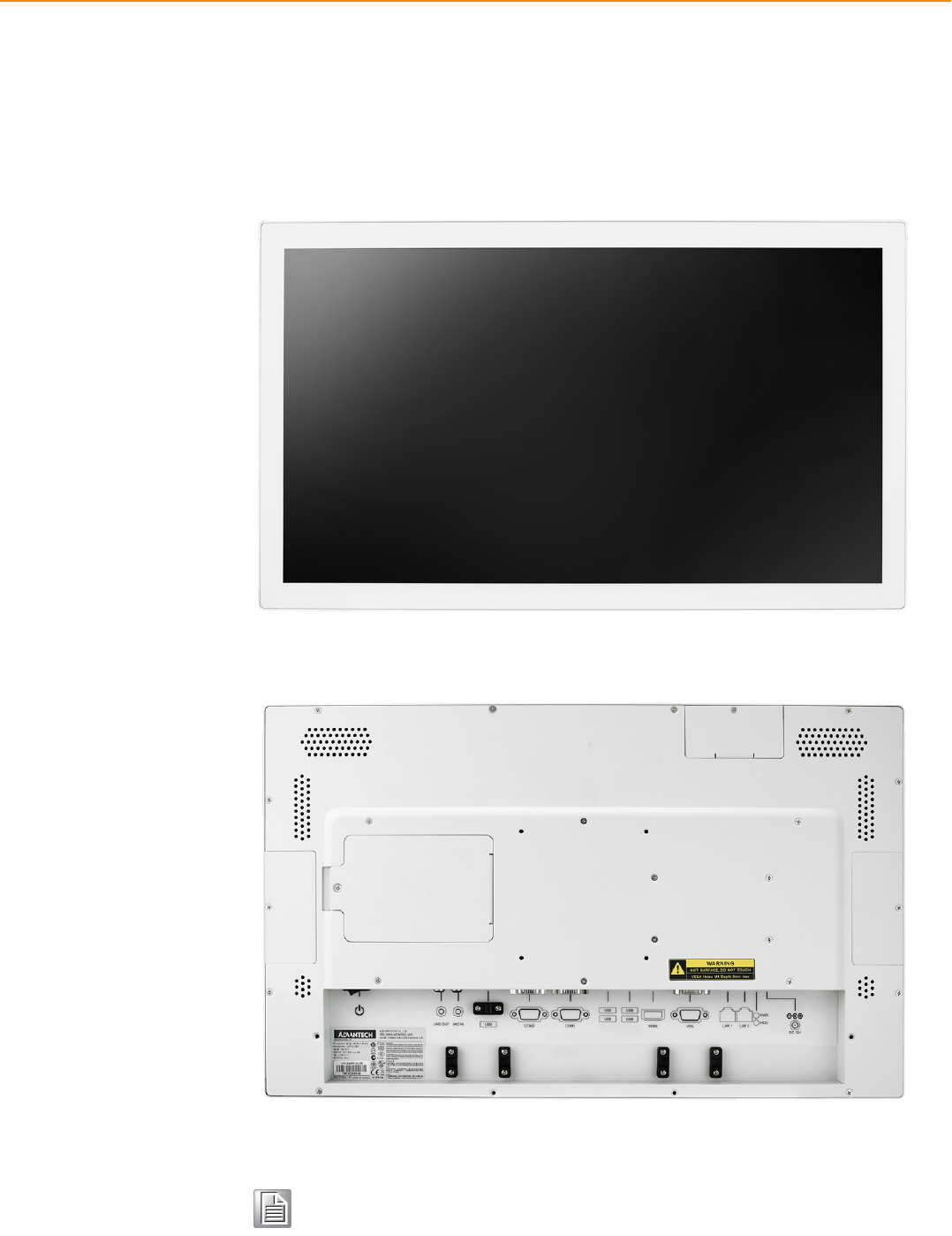
2.1 Quick Start Tour
Before beginning system setup, take a moment to become familiar with the connector
locations and functions, as shown in the figures below.
2.1.1 Front View
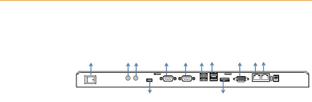
2.1.2 Rear View
Note! Use only VESA-compatible floor, stand, and wall mount kits.
See Appendix A for additional details.
Refer to Section 2.2 regarding system I/O according to UTC model.
7 UTC-520 User Manual
Chapter 2 System Setup
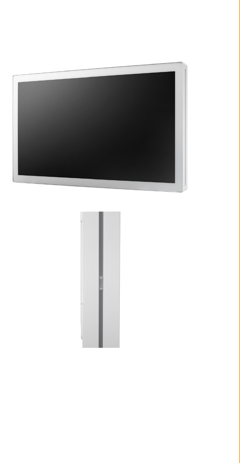
2.1.3 Side View
UTC-520 User Manual 8
2.2 I/O Ports
2.2.1 UTC-520FP-IKA0E
A. Power Switch H. USB 3.0 x 2
B. Line-Out I. HDMI
C. Mic-In J. VGA
D. USB for bottom side peripheral module K. LAN 1
E. COM2 L. LAN 2
F. COM1 M. DC Input
G. USB 2.0 x 2
2.3 Setup Procedures
2.3.1 System Power On
1. For the UTC-520FP-IKA0E models, a 12V/7A power adaptor.
2. Hold power cords by the plugs ends only. Refer to Section 2.2 for the location of
the DC/AC power input and power switch.
3. Press the power switch to activate the system. The PWR LED should emit a
green light.
2.3.2 BIOS Setup
For most UTC series, the system setup and configuration will be completed by the
dealer or system integrator prior to delivery. However, users may still need to access
the BIOS setup program to adjust the system configuration, such as the date/ time or
hard drive type. The setup program is stored in read-only memory (ROM) and can be
accessed following system reset or by pressing the “Del” key after powering on the
computer. The settings selected in the setup program are recorded in CMOS RAM
memory, which is backed up by a battery to ensure the settings are retained after the
system is powered off. When booting up, the system compares the settings stored in
CMOS RAM with the POST self test results. If a discrepancy is found, an error mes-
sage is displayed on screen and users are prompted to run the setup program.
A B C
D
E F G
H
I
J K L M

9 UTC-520 User Manual
Chapter 2 System Setup
2.3.3 System Software Installation
Recent releases of operating systems from major vendors include setup programs
that load automatically and guide users through hard disk preparation and operating
system installation. Some distributors and system integrators may have already
installed software prior to shipping the product.
2.3.4 Driver Installation
After installing the system software, users can set up the Ethernet, XGA, audio, and
touchscreen functions.
Note! Before software or driver installation, the system must be equipped with
additional storage that users must purchase separately.
Note! The relevant drivers and utilities are subject to change without notice.
Download the latest drivers for UTC series products from the Advantech
website at http://support.advantech.com or contact our application
engineers for further assistance.

UTC-520 User Manual 10

Chapter 3
3Upgrades and
Installation

UTC-520 User Manual 12
3.1 Introduction
Advantech’s UTC series systems are PC-based computers housed in an aluminum
enclosure. To perform system maintenance or hardware upgrades, such as installing
an HDD, DRAM, or CompactFlash (A/B models only), simply remove the unit’s rear
cover.
Warning! Do not remove the rear cover until you have verified that power is not
flowing within the device. The system power should be switched off and
the power cord unplugged before opening the device enclosure.
13 UTC-520 User Manual
Chapter 3 Upgrades and Installation
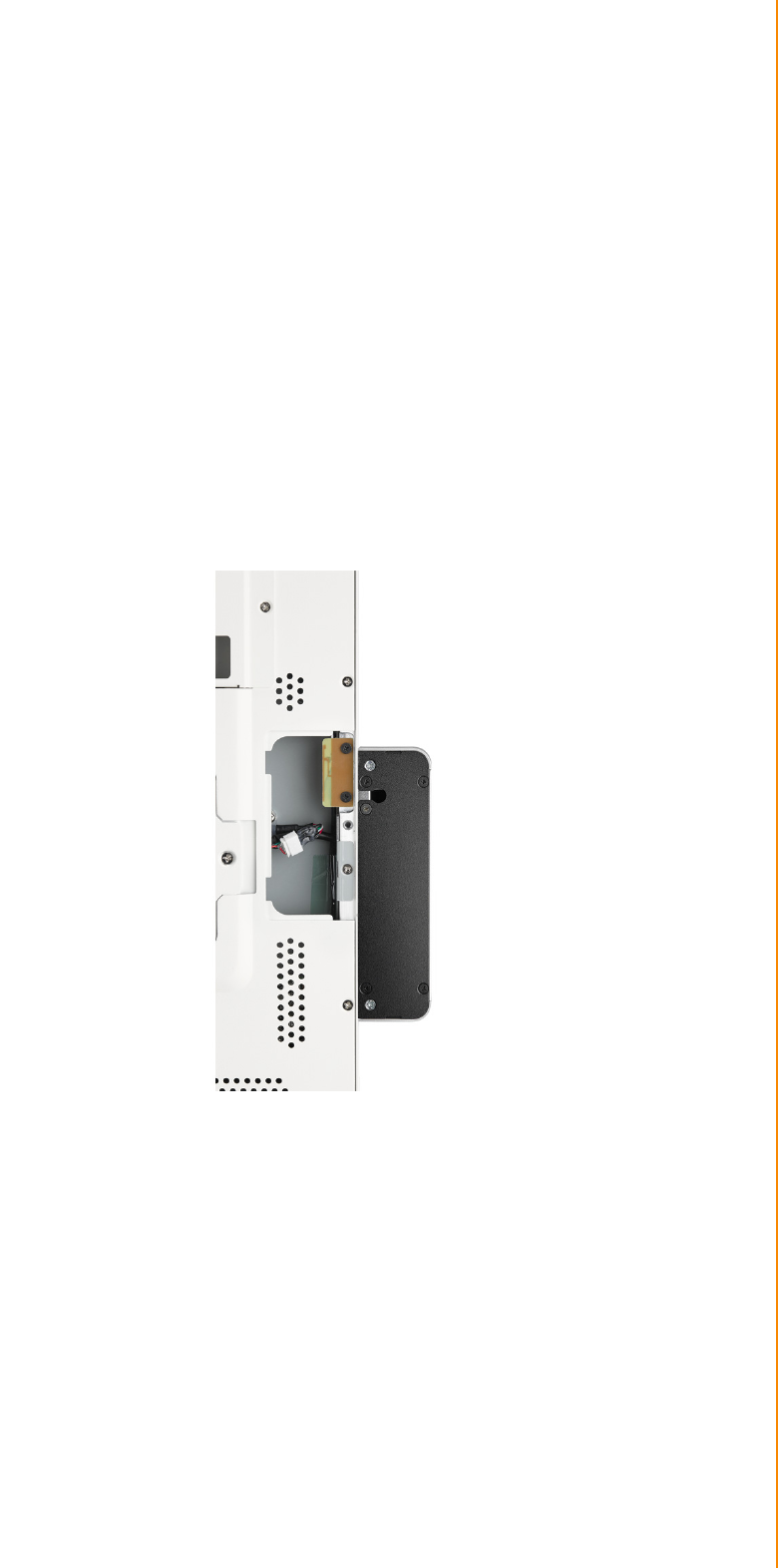
3.2 Installing Peripherals (Optional)
3.2.1 UTC-520FP-IKA0E
1. Switch off the unit.
2. Locate the peripheral cable port you want to use.
3. Remove the rubber cap.
4. Open the peripheral cover accordingly.
5. Route the cable from the peripheral module through the cable port inside the
unit.
6. Connect the cable to the USB port.
7. Attach the peripheral module to the groove rail and let the cable sink into the
groove.
8. Fasten the 2 screws to fix the peripheral module in place.
9. Close the peripheral cover.

UTC-520 User Manual 14

15 UTC-520 User Manual
Chapter 3 Upgrades and Installation

www.advantech.com
Please verify specifications before quoting. This guide is intended for reference
purposes only.
All product specifications are subject to change without notice.
No part of this publication may be reproduced in any form or by any means,
such as electronically, by photocopying, recording, or otherwise, without prior
written permission from the publisher.
All brand and product names are trademarks or registered trademarks of their
respective companies.
© Advantech Co., Ltd. 2018

17 XXX-XXXX User Manual