Advantech Co VITA-350 Automated Vehicle Location Device User Manual VITA 350 Book
Advantech Co Ltd Automated Vehicle Location Device VITA 350 Book
UserManual.wiki
>
Advantech Co
>
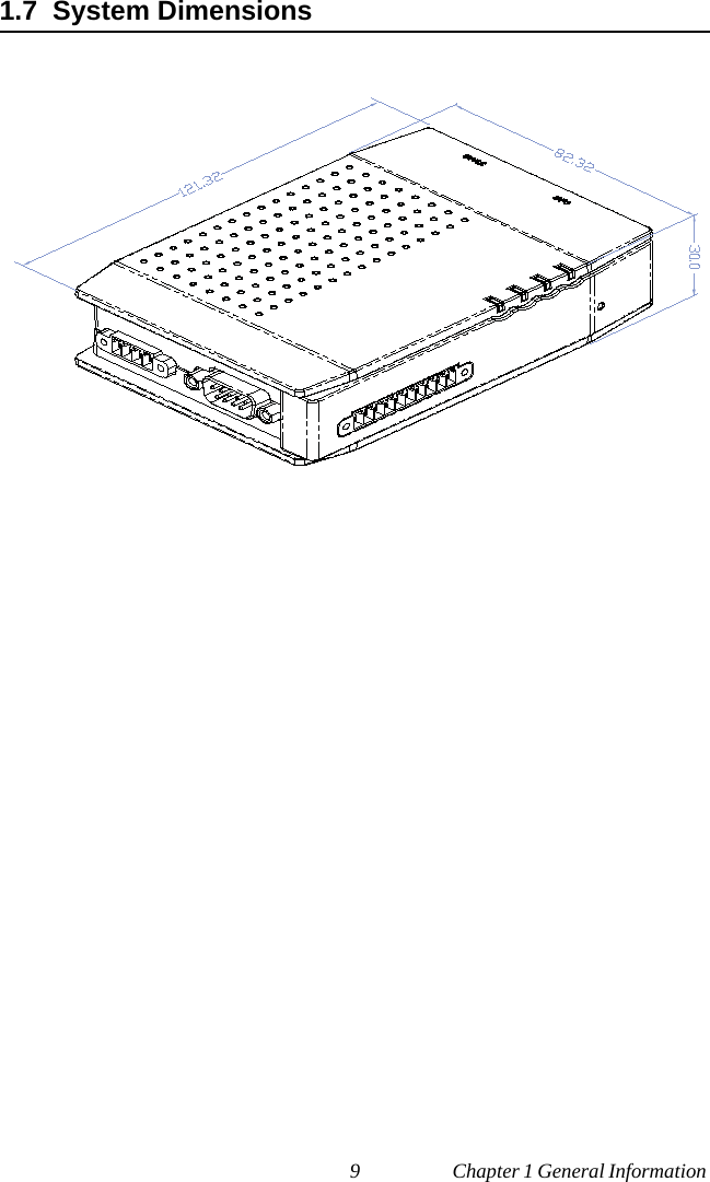
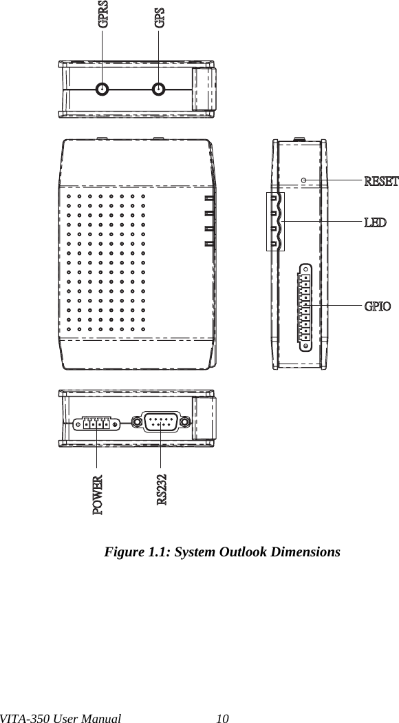
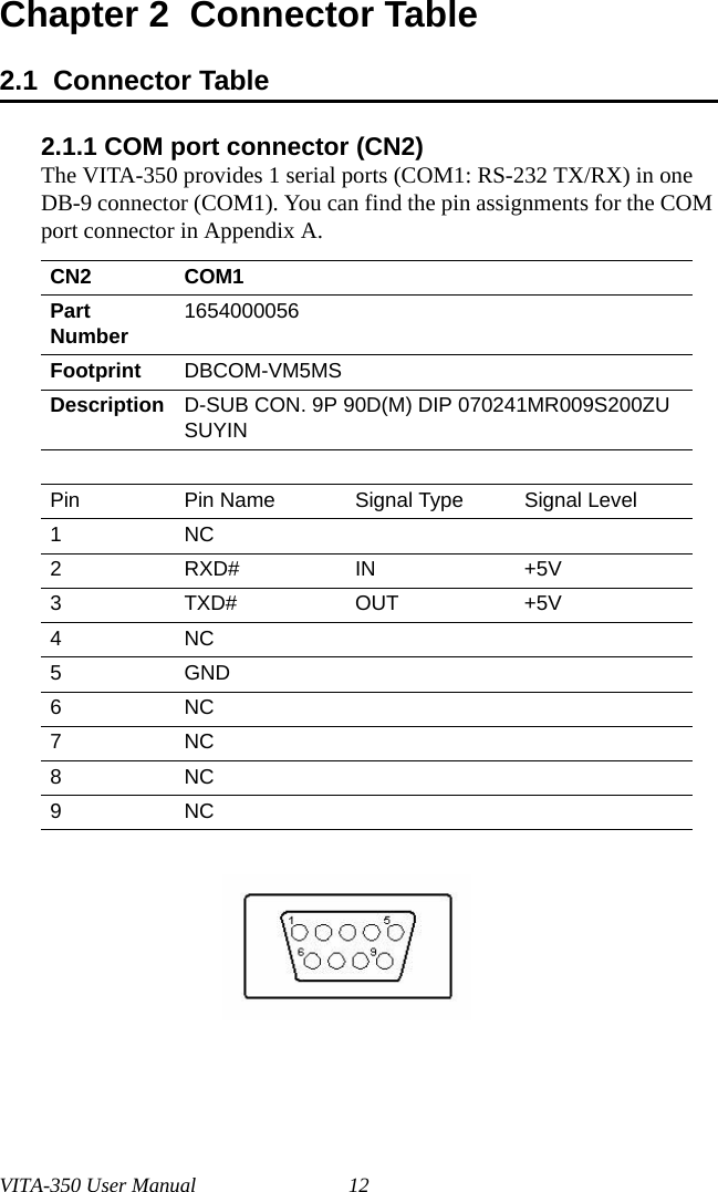
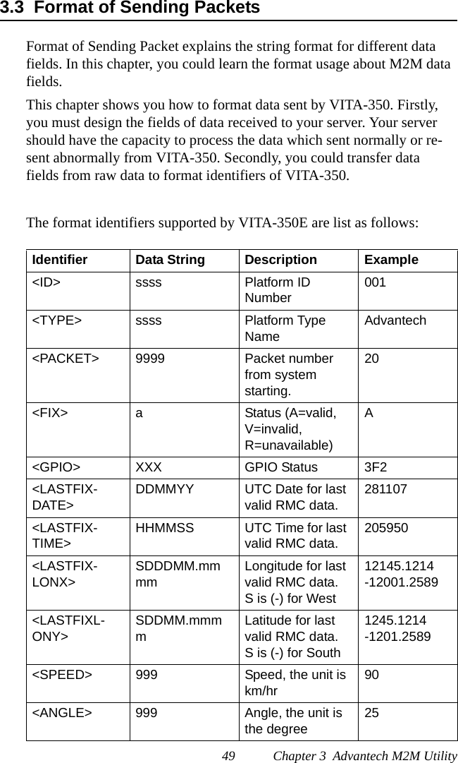
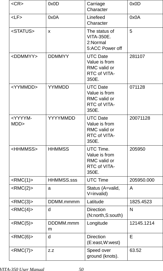
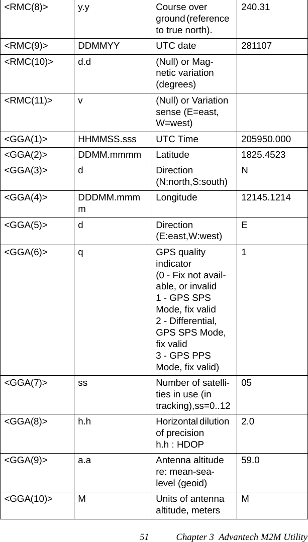
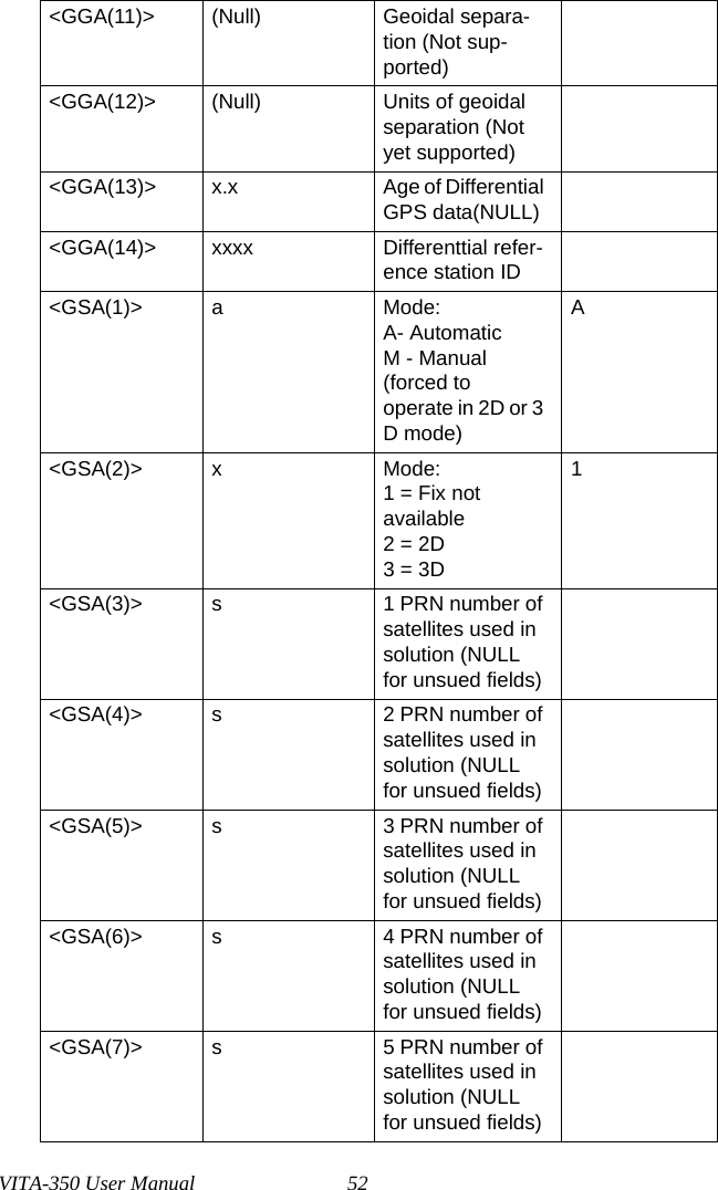
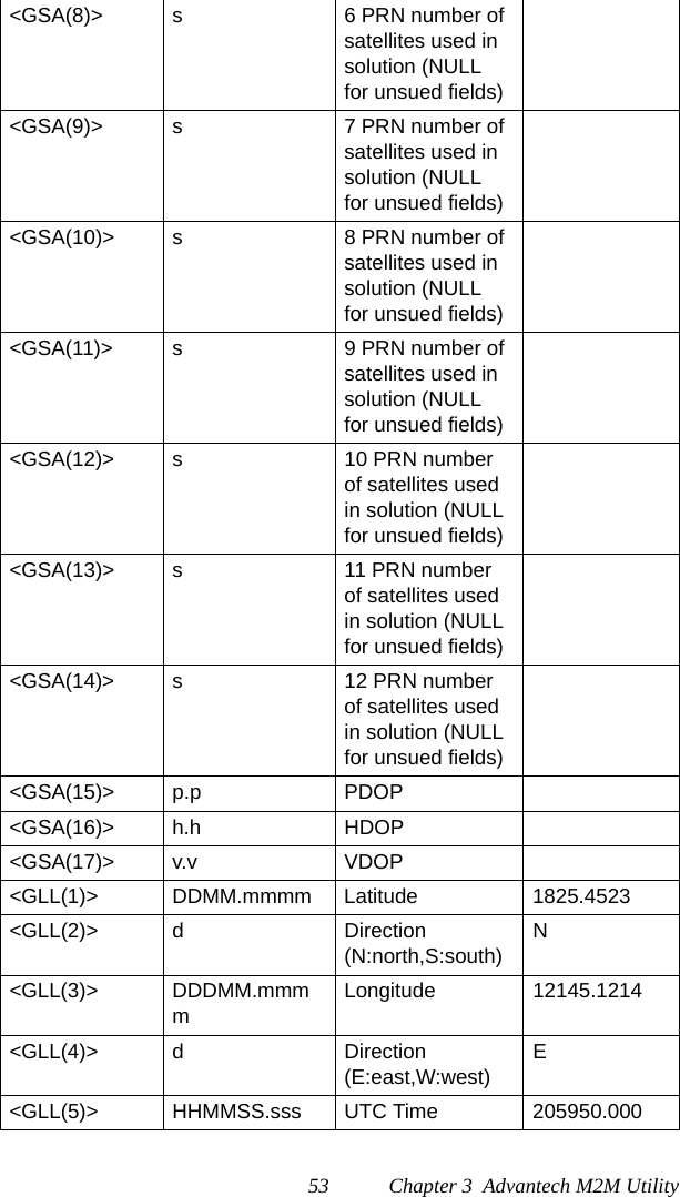
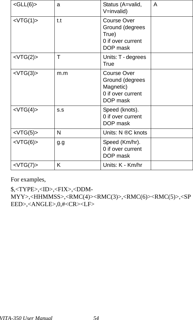
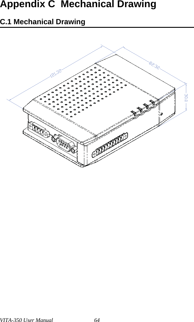
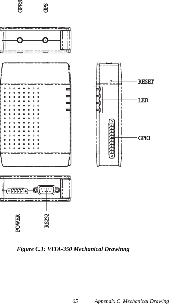
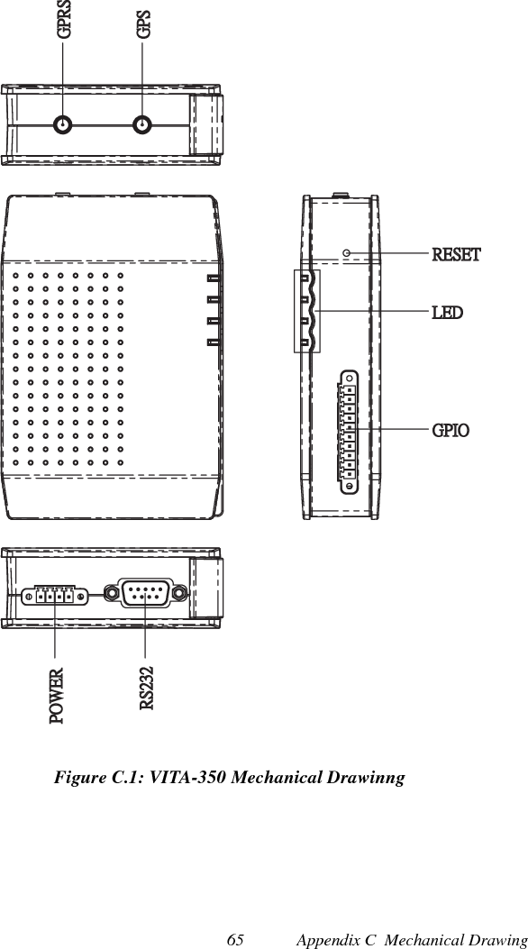
VITA 350 User Manual
Manual
Navigation menu
Upload a User Manual
Namespaces
Wiki Guide
HTML
PDF
Info
Views
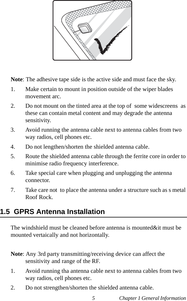
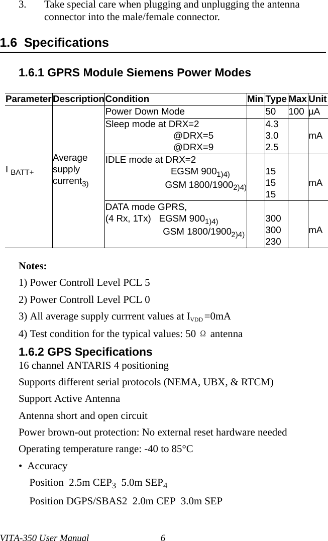
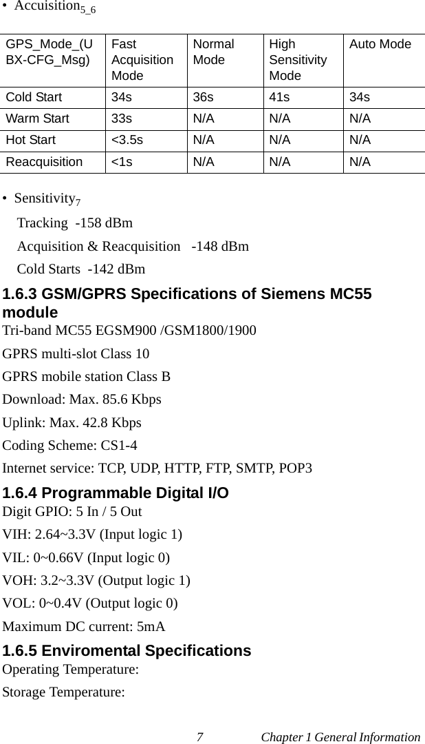
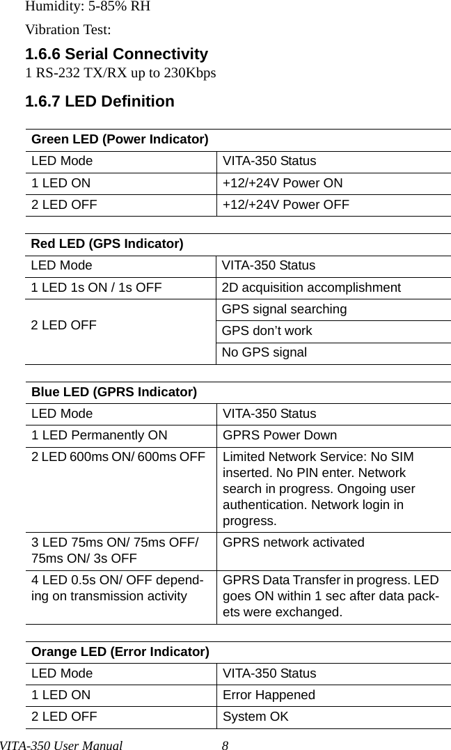
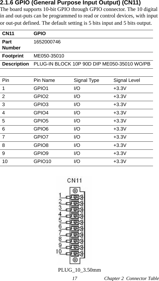
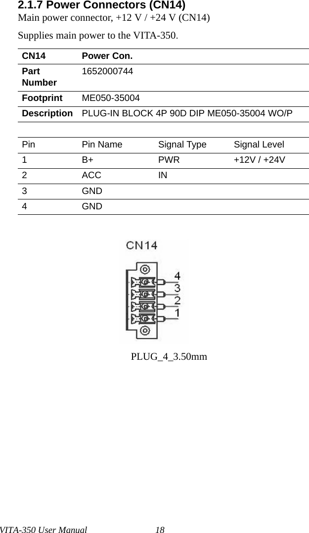
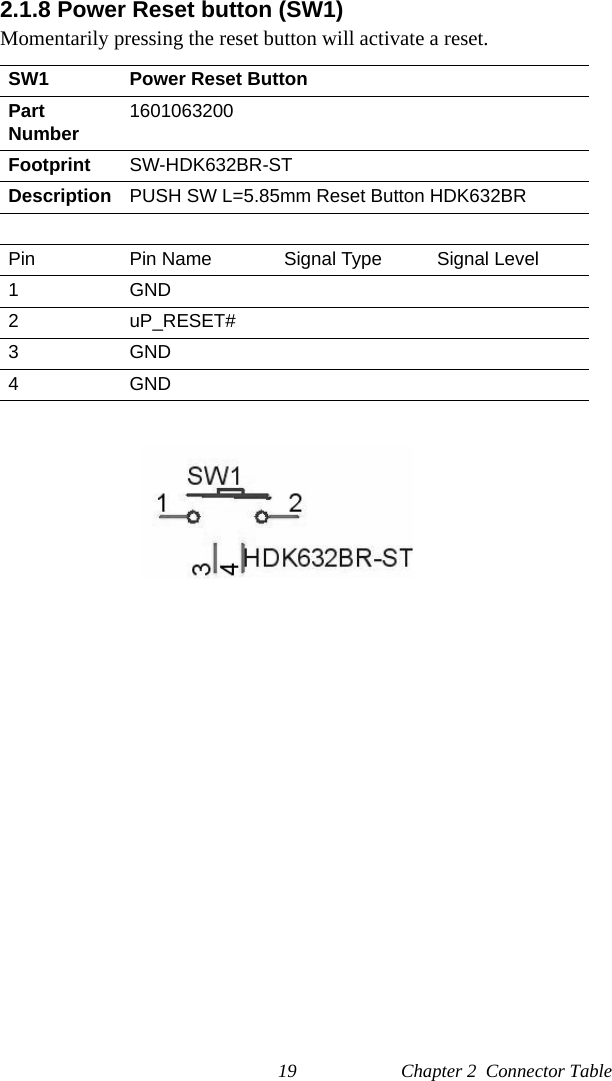
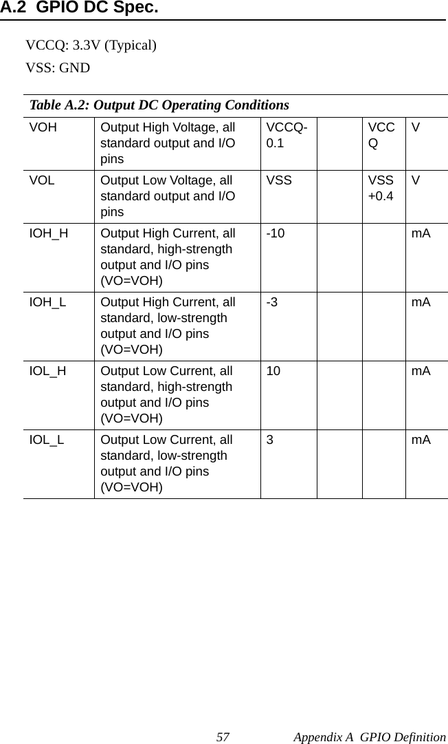
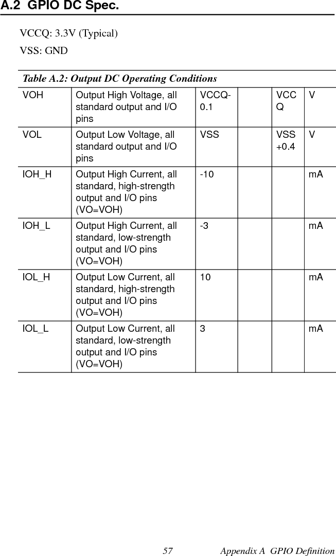
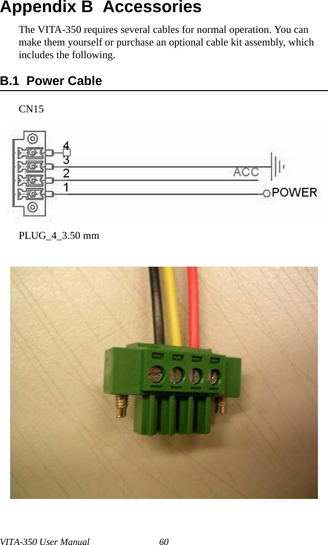
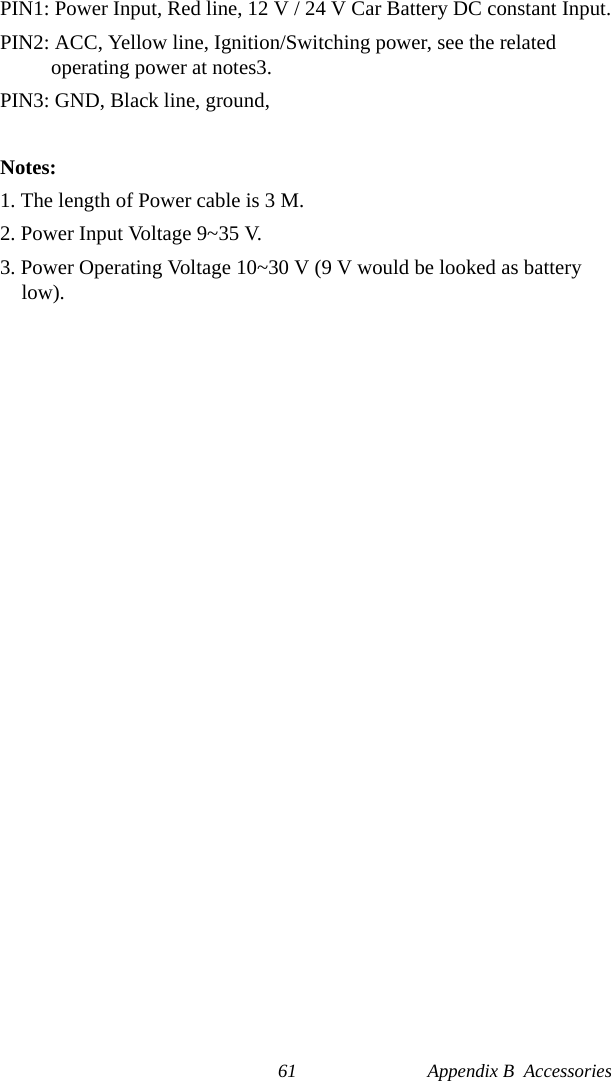
User Manual
Discussion / Help
Navigation