Advantech Co WISE1510 M2.COM LoRa IoT Node User Manual
Advantech Co Ltd M2.COM LoRa IoT Node Users Manual
UserManual.wiki
>
Advantech Co
>
WISE1510 User Manual
Users Manual
Navigation menu
Upload a User Manual
Namespaces
Wiki Guide
HTML
PDF
Info
Views
User Manual
Discussion / Help
Navigation
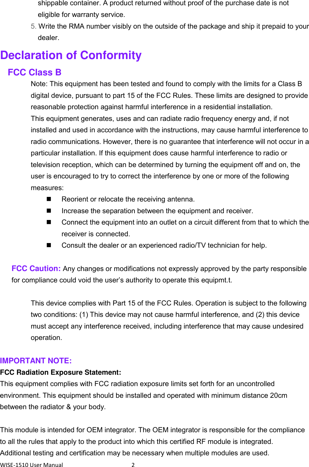
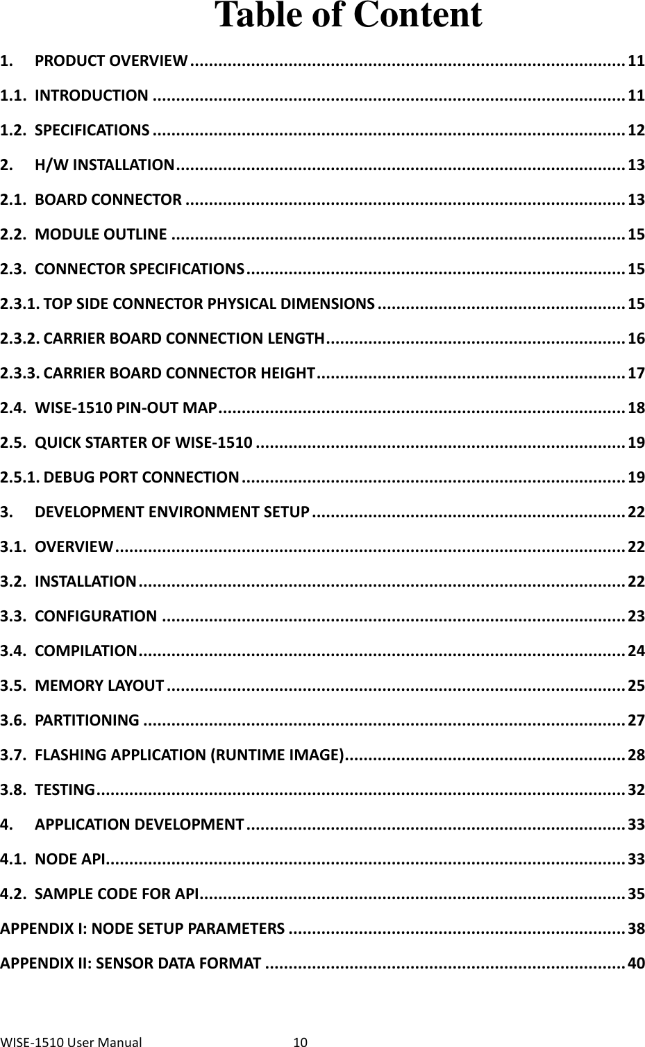
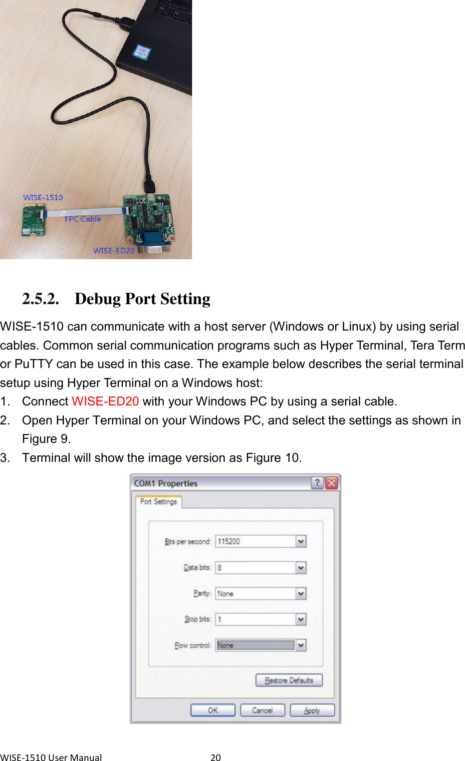
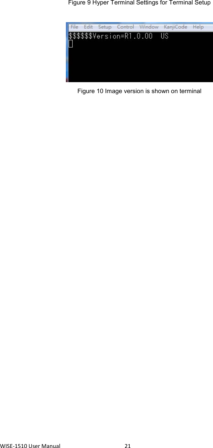
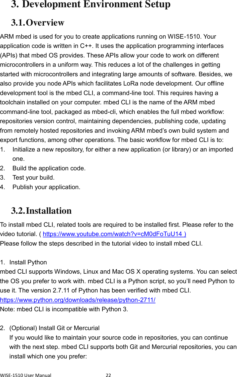
![WISE-1510 User Manual 23 Git - version 1.9.5 or later ( https://git-scm.com/ ). Mercurial - version 2.2.2 or later ( https://www.mercurial-scm.org/ ). If you don’t want to use repositories, you can just skip it. 3. Install gcc mbed CLI invokes the mbed OS 5 tools for various features, such as compiling, testing and exporting to industry standard toolchains. To compile your code, you will need either a compiler or an IDE: Compilers: GCC ARM, ARM Compiler 5, IAR. IDE: Keil uVision, DS-5, IAR Workbench. We select GCC ARM Embedded, so you can install version 4.9 of GCC ARM Embedded ( https://launchpad.net/gcc-arm-embedded ). Note: Version 5.0 or any other versions above may be incompatible with the tools. 4. Install mbed CLI You can get the latest stable version of mbed CLI from PyPI $ pip install mbed-cli Note: On Linux or Mac, you may need to run with sudo. Finally, you’ve to extract the source code to the working directory from the SDK we released. The structure of the working directory is as below: docs/ <-- Documents for SDK loranode_L443_sdk_R1_0_02/mbed-os/ <-- mbed os loranode_L443_sdk_R1_0_02/libHLLoraNode.a <-- Harmony Link Lora Node library loranode_L443_sdk_R1_0_02/node_api.h <-- Node API header file loranode_L443_sdk_R1_0_02/main.cpp <-- Sample code 3.3. Configuration After the installation of required tool chains, please set up the directory of mbed CLI to link the folder of toolchains which you want to use for compiling the source tree. You can set the GCC ARM Embedded location via the command as below: $ mbed config --global GCC_ARM_PATH "C:\Program Files\GCC_ARM" [mbed] C:\Program Files\GCC_ARM now set as global GCC_ARM_PATH](https://usermanual.wiki/Advantech-Co/WISE1510/User-Guide-3400123-Page-24.png)
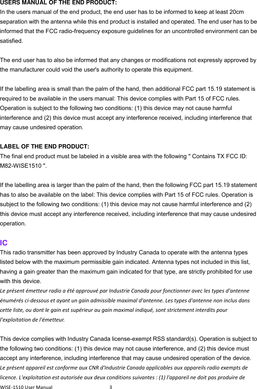
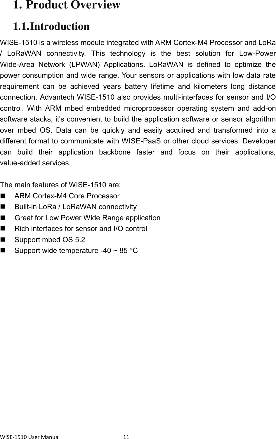
![WISE-1510 User Manual 24 Next, you can select the tool chain and target platform which mbed CLI uses to build applications. Change directory to target mbed program. $ mbed config target NUCLEO_L443RC [mbed] NUCLEO_L443RC now set as default target in program "xxxxx" $ mbed config toolchain GCC_ARM [mbed] GCC_ARM now set as default toolchain in program "xxxx" You can see the active mbed CLI configuration via: $ mbed config --list [mbed] Global config: GCC_ARM_PATH =C:\Program Files\GCC_ARM [mbed] Local config (xxxx): TOOLCHAIN=GCC_ARM TARGET=NUCLEO_L443RC 3.4. Compilation mbed CLI uses the current directory as a working context. This means that before calling any mbed CLI command, you must first change to the working directory containing the code. Then, Use the mbed compile command to compile your code: $ mbed compile -c Building project xxxxx (NUCLEO_L443RC, GCC_ARM) Scan: . Scan: mbed Scan: env Compile [ 0.5%]: base64.cpp Compile [ 1.0%]: oslmic.cpp … Compile [100.0%]: node_sapi.cpp Link: xxxxx Elf2Bin: xxxxx +--------------------+--------+-------+-------+ | Module | .text | .data | .bss | +--------------------+--------+-------+-------+ | Fill | 223 | 16 | 41 | | Misc | 104316 | 7804 | 5017 | | drivers | 3592 | 4 | 224 |](https://usermanual.wiki/Advantech-Co/WISE1510/User-Guide-3400123-Page-25.png)