Advantech Co WISE1510 M2.COM LoRa IoT Node User Manual
Advantech Co Ltd M2.COM LoRa IoT Node Users Manual
Users Manual

User Manual
WISE-1510
M2.COM LoRa IoT Node
WISE-1510 User Manual 1
Copyright
The documentation and the software included with this product are copyrighted 2016
by Advantech Co., Ltd. All rights are reserved. Advantech Co., Ltd. reserves the right
to make improvements in the products described in this manual at any time without
notice. No part of this manual may be reproduced, copied, translated or transmitted
in any form or by any means without the prior written permission of Advantech Co.,
Ltd. Information provided in this manual is intended to be accurate and reliable. However,
Advantech Co., Ltd. assumes no responsibility for its use, nor for any infringements
of the rights of third parties, which may result from its use.
Acknowledgements
ARM is trademarks of ARM Corporation.
Freescale is trademarks of Freescale Corporation.
Microsoft Windows are registered trademarks of Microsoft Corp.
All other product names or trademarks are properties of their respective owners.
Product Warranty (2 years)
Advantech warrants to you, the original purchaser, that each of its products will be
free from defects in materials and workmanship for two years from the date of purchase.
This warranty does not apply to any products which have been repaired or altered by
persons other than repair personnel authorized by Advantech, or which have been
subject to misuse, abuse, accident or improper installation. Advantech assumes no
liability under the terms of this warranty as a consequence of such events.
Because of Advantech’s high quality-control standards and rigorous testing, most of
our customers never need to use our repair service. If an Advantech product is defective,
it will be repaired or replaced at no charge during the warranty period. For out-of-
warranty repairs, you will be billed according to the cost of replacement materials,
service time and freight. Please consult your dealer for more details.
If you think you have a defective product, follow these steps:
1. Collect all the information about the problem encountered. (For example, CPU speed,
Advantech products used, other hardware and software used, etc.) Note anything
abnormal and list any onscreen messages you get when the problem occurs.
2. Call your dealer and describe the problem. Please have your manual, product, and any
helpful information readily available.
3. If your product is diagnosed as defective, obtain an RMA (return merchandize
authorization) number from your dealer. This allows us to process your return more
quickly.
4. Carefully pack the defective product, a fully-completed Repair and Replacement Order
Card and a photocopy proof of purchase date (such as your sales receipt) in a
WISE-1510 User Manual 2
shippable container. A product returned without proof of the purchase date is not
eligible for warranty service.
5. Write the RMA number visibly on the outside of the package and ship it prepaid to your
dealer.
Declaration of Conformity
FCC Class B
Note: This equipment has been tested and found to comply with the limits for a Class B
digital device, pursuant to part 15 of the FCC Rules. These limits are designed to provide
reasonable protection against harmful interference in a residential installation.
This equipment generates, uses and can radiate radio frequency energy and, if not
installed and used in accordance with the instructions, may cause harmful interference to
radio communications. However, there is no guarantee that interference will not occur in a
particular installation. If this equipment does cause harmful interference to radio or
television reception, which can be determined by turning the equipment off and on, the
user is encouraged to try to correct the interference by one or more of the following
measures:
Reorient or relocate the receiving antenna.
Increase the separation between the equipment and receiver.
Connect the equipment into an outlet on a circuit different from that to which the
receiver is connected.
Consult the dealer or an experienced radio/TV technician for help.
FCC Caution: Any changes or modifications not expressly approved by the party responsible
for compliance could void the user’s authority to operate this equipmt.t.
This device complies with Part 15 of the FCC Rules. Operation is subject to the following
two conditions: (1) This device may not cause harmful interference, and (2) this device
must accept any interference received, including interference that may cause undesired
operation.
IMPORTANT NOTE:
FCC Radiation Exposure Statement:
This equipment complies with FCC radiation exposure limits set forth for an uncontrolled
environment. This equipment should be installed and operated with minimum distance 20cm
between the radiator & your body.
This module is intended for OEM integrator. The OEM integrator is responsible for the compliance
to all the rules that apply to the product into which this certified RF module is integrated.
Additional testing and certification may be necessary when multiple modules are used.
WISE-1510 User Manual 3
USERS MANUAL OF THE END PRODUCT:
In the users manual of the end product, the end user has to be informed to keep at least 20cm
separation with the antenna while this end product is installed and operated. The end user has to be
informed that the FCC radio-frequency exposure guidelines for an uncontrolled environment can be
satisfied.
The end user has to also be informed that any changes or modifications not expressly approved by
the manufacturer could void the user's authority to operate this equipment.
If the labelling area is small than the palm of the hand, then additional FCC part 15.19 statement is
required to be available in the users manual: This device complies with Part 15 of FCC rules.
Operation is subject to the following two conditions: (1) this device may not cause harmful
interference and (2) this device must accept any interference received, including interference that
may cause undesired operation.
LABEL OF THE END PRODUCT:
The final end product must be labeled in a visible area with the following " Contains TX FCC ID:
M82-WISE1510 ".
If the labelling area is larger than the palm of the hand, then the following FCC part 15.19 statement
has to also be available on the label: This device complies with Part 15 of FCC rules. Operation is
subject to the following two conditions: (1) this device may not cause harmful interference and (2)
this device must accept any interference received, including interference that may cause undesired
operation.
IC
This radio transmitter has been approved by Industry Canada to operate with the antenna types
listed below with the maximum permissible gain indicated. Antenna types not included in this list,
having a gain greater than the maximum gain indicated for that type, are strictly prohibited for use
with this device.
Le présent émetteur radio a été approuvé par Industrie Canada pour fonctionner avec les types d'antenne
énumérés ci-dessous et ayant un gain admissible maximal d'antenne. Les types d'antenne non inclus dans
cette liste, ou dont le gain est supérieur au gain maximal indiqué, sont strictement interdits pour
l'exploitation de l'émetteur.
This device complies with Industry Canada license-exempt RSS standard(s). Operation is subject to
the following two conditions: (1) this device may not cause interference, and (2) this device must
accept any interference, including interference that may cause undesired operation of the device.
Le présent appareil est conforme aux CNR d'Industrie Canada applicables aux appareils radio exempts de
licence. L'exploitation est autorisée aux deux conditions suivantes : (1) l'appareil ne doit pas produire de

WISE-1510 User Manual 4
brouillage, et (2) l'utilisateur de l'appareil doit accepter tout brouillage radioélectrique subi, même si le
brouillage est susceptible d'en compromettre le fonctionnement.
This radio transmitter (9404A-WISE1510) has been approved by Industry Canada to operate with
the antenna types listed below with the maximum permissible gain indicated. Antenna types not
included in this list, having a gain greater than the maximum gain indicated for that type, are strictly
prohibited for use with this device.
Le présent émetteur radio (9404A-WISE1510) a été approuvé par Industrie Canada pour fonctionner avec
les types d'antenne énumérés ci-dessous et ayant un gain admissible maximal d'antenne. Les types
d'antenne non inclus dans cette liste, ou dont le gain est supérieur au gain maximal indiqué, sont
strictement interdits pour l'exploitation de l'émetteur.
Antenna list:
Part No.
MPN
Description
1750008625-01
TH-915i
Dipole Ant. SUB-1G 1.8dBi SMA/M BLK 902-928 IPX6
IMPORTANT NOTE:
IC Radiation Exposure Statement:
This equipment complies with IC RSS-102 radiation exposure limits set forth for an uncontrolled
environment. This equipment should be installed and operated with minimum distance 20cm
between the radiator & your body.
Cet équipement est conforme aux limites d'exposition aux rayonnements IC établies pour un environnement
non contrôlé. Cet équipement doit être installé et utilisé avec un minimum de 20 cm de distance entre la
source de rayonnement et votre corps.
This module is intended for OEM integrator. The OEM integrator is responsible for the compliance
to all the rules that apply to the product into which this certified RF module is integrated.
Additional testing and certification may be necessary when multiple modules are used.
Any changes or modifications not expressly approved by the manufacturer could void the user's
authority to operate this equipment.
USERS MANUAL OF THE END PRODUCT:
In the users manual of the end product, the end user has to be informed to keep at least 20cm
separation with the antenna while this end product is installed and operated. The end user has to be
informed that the IC radio-frequency exposure guidelines for an uncontrolled environment can be
satisfied.
The end user has to also be informed that any changes or modifications not expressly approved by
WISE-1510 User Manual 5
the manufacturer could void the user's authority to operate this equipment. Operation is subject to
the following two conditions: (1) this device may not cause harmful interference and (2) this device
must accept any interference received, including interference that may cause undesired operation.
LABEL OF THE END PRODUCT:
The final end product must be labeled in a visible area with the following " Contains IC:
9404A-WISE1510 ".
The Host Model Number (HMN) must be indicated at any location on the exterior of the end product
or product packaging or product literature which shall be available with the end product or online.

WISE-1510 User Manual 6
Packing List
Before setting up the system, check that the items listed below are included and in good condition. If
any item does not accord with the table, please contact your dealer immediately.
1 WISE-1510
1 Screw for WISE-1510
1 China RoHs Notice
Optional Accessories
Part No.
Description
1750008598-01
Sub G antenna Dipole L=195mm, 1dBi 902~928 MHz
1750008599-01
Sub G antenna Dipole L=195mm, 1dBi 863~870 MHz
1750008569-01
Antenna Cable SMA to MHF4 L=300mm
1700015038
FPC Cable 10P-0.5mm 7.9cm for DCU2.0
9696WED200E
ASS'Y WISE-ED20 A101-1 M2.COM Daughter
1931000590
Screw M2.5x5L F/S D=5.3 H=0.8 (1+) ST Ni
1700023619-01
A cable USB-A 4P(M)/micro USB 5P(M) 1m ADAM-T212
1700025876-01
M cable USB-A 4P(M)/Plug-in 2P-5.0 90CM
XRISC-ADP-10HW-AG
ADP A/D 100-240V 10W 5V WM
193A231540
POST F=M3*6L M=M3*6L D=5 d=2.88 B=5 H=15 Cu
Development Board
Part No.
Description
9696150000E
ASS'Y WISE-DB1500 A101-1 M2.COM CARRIER
Ordering Information
Part No.
WISE-1510WMB-SDA1N
Frequency Band
902-928MHz for North America (LoRaWAN)
Part No.
WISE-1510WMB-SDA1E
Frequency Band
863-870MHz for Europe (LoRaWAN)
WISE-1510 User Manual 7
WISE-1510 User Manual 8
Safety Instructions
1. Read these safety instructions carefully.
2. Keep this User Manual for later reference.
3. Disconnect this equipment from any AC outlet before cleaning. Use a damp cloth. Do
not use liquid or spray detergents for cleaning.
4. For plug-in equipment, the power outlet socket must be located near the equipment
and must be easily accessible.
5. Keep this equipment away from humidity.
6. Put this equipment on a reliable surface during installation. Dropping it or letting it fall
may cause damage.
7. The openings on the enclosure are for air convection. Protect the equipment from
overheating. DO NOT COVER THE OPENINGS.
8. Make sure the voltage of the power source is correct before connecting the equipment
to the power outlet.
9. Position the power cord so that people cannot step on it. Do not place anything over the
power cord.
10. All cautions and warnings on the equipment should be noted.
11. If the equipment is not used for a long time, disconnect it from the power source to
avoid damage by transient overvoltage.
12. Never pour any liquid into an opening. This may cause fire or electrical shock.
13. Never open the equipment. For safety reasons, the equipment should be opened only
by qualified service personnel.
14. If one of the following situations arises, get the equipment checked by service
personnel:
The power cord or plug is damaged.
Liquid has penetrated into the equipment.
The equipment has been exposed to moisture.
The equipment does not work well, or you cannot get it to work according to the
user's manual.
The equipment has been dropped and damaged.
The equipment has obvious signs of breakage.
DISCLAIMER: This set of instructions is given according to IEC 704-1. Advantech
disclaims all responsibility for the accuracy of any statements contained herein.

WISE-1510 User Manual 9
Change Log:
Date
Version
Description / Major change
2017/01/05
V0.1
Draft version
2017/02/03
V0.2
Modify chapter 3.2 & 3.3 and add Figure. 10
2017/02/13
V0.3
Update optional accessory with Sub G antenna
Chapter 5 is added for the instruction to enable LoRaWAN
2017/03/14
V0.4
Modify chapter 3.5~3.7 and 4.
2017/04/10
V0.5
Add chapter 3.5 Memory Layout and update 3.6~3.7
2017/04/12
V0.6
Remove Chapter 1.3, update page 2~3 Declaration of
Conformity, Chapter 3.6 and add appendix I and II
2017/04/19
V0.7
Update page 2~5 Declaration of Conformity
WISE-1510 User Manual 10
Table of Content
1. PRODUCT OVERVIEW ............................................................................................. 11
1.1. INTRODUCTION ..................................................................................................... 11
1.2. SPECIFICATIONS ..................................................................................................... 12
2. H/W INSTALLATION ................................................................................................ 13
2.1. BOARD CONNECTOR .............................................................................................. 13
2.2. MODULE OUTLINE ................................................................................................. 15
2.3. CONNECTOR SPECIFICATIONS ................................................................................. 15
2.3.1. TOP SIDE CONNECTOR PHYSICAL DIMENSIONS ..................................................... 15
2.3.2. CARRIER BOARD CONNECTION LENGTH ................................................................ 16
2.3.3. CARRIER BOARD CONNECTOR HEIGHT .................................................................. 17
2.4. WISE-1510 PIN-OUT MAP ....................................................................................... 18
2.5. QUICK STARTER OF WISE-1510 ............................................................................... 19
2.5.1. DEBUG PORT CONNECTION .................................................................................. 19
3. DEVELOPMENT ENVIRONMENT SETUP ................................................................... 22
3.1. OVERVIEW ............................................................................................................. 22
3.2. INSTALLATION ........................................................................................................ 22
3.3. CONFIGURATION ................................................................................................... 23
3.4. COMPILATION ........................................................................................................ 24
3.5. MEMORY LAYOUT .................................................................................................. 25
3.6. PARTITIONING ....................................................................................................... 27
3.7. FLASHING APPLICATION (RUNTIME IMAGE) ............................................................ 28
3.8. TESTING ................................................................................................................. 32
4. APPLICATION DEVELOPMENT ................................................................................. 33
4.1. NODE API............................................................................................................... 33
4.2. SAMPLE CODE FOR API ........................................................................................... 35
APPENDIX I: NODE SETUP PARAMETERS ........................................................................ 38
APPENDIX II: SENSOR DATA FORMAT ............................................................................. 40
WISE-1510 User Manual 11
1. Product Overview
1.1. Introduction
WISE-1510 is a wireless module integrated with ARM Cortex-M4 Processor and LoRa
/ LoRaWAN connectivity. This technology is the best solution for Low-Power
Wide-Area Network (LPWAN) Applications. LoRaWAN is defined to optimize the
power consumption and wide range. Your sensors or applications with low data rate
requirement can be achieved years battery lifetime and kilometers long distance
connection. Advantech WISE-1510 also provides multi-interfaces for sensor and I/O
control. With ARM mbed embedded microprocessor operating system and add-on
software stacks, it's convenient to build the application software or sensor algorithm
over mbed OS. Data can be quickly and easily acquired and transformed into a
different format to communicate with WISE-PaaS or other cloud services. Developer
can build their application backbone faster and focus on their applications,
value-added services.
The main features of WISE-1510 are:
ARM Cortex-M4 Core Processor
Built-in LoRa / LoRaWAN connectivity
Great for Low Power Wide Range application
Rich interfaces for sensor and I/O control
Support mbed OS 5.2
Support wide temperature -40 ~ 85 °C

WISE-1510 User Manual 12
1.2. Specifications
Processor System
MCU
ARM Cortex-M4 Core Processor 80MHz
STM – STM32L443RC
Memory
RAM
64KB
Flash
256KB
Form Factor
M2.COM Type A 2230
Spec. Standard
M2 COM Technical SPEC_v1.1
Wireless Network
Standard
LoRa Proprietary (Harmony Link) / LoRaWAN
Frequency
Band
863-870MHz for Europe (LoRaWAN)
902-928MHz* for North America (LoRaWAN)
Channels
Spreading Factor: 7 ~ 12
Topology
Star network
Transmit
Power
Up to +18dBm
Receiver
Sensitivity
Up to -136dBm at SF = 12 / 125KHz
RF Data
Rate
50 kbps at FSK mode EU868
(Based on LoRaWAN spec 1R0 version)
21.9 kbps at SF7 mode US915
(Based on LoRaWAN spec 1R0 version)
Function
End node
Antenna
connector
MHF4 connector
I/O
UART
1 (4-wire, support RTC/CTS)
I2C
1
GPIO
8
PWM
1
SPI
1
ADC
4
USB
1 (device only)
Programming / Debug
Port
1 via WISE-ED20 (CN1)
Power
3.3V
Environment
Operational
Temperature
-40 ~ 85° C
Operating
Humidity
5% ~ 95% Relative Humidity, non-condensing
WISE-1510 User Manual 13
Physical
Characteristics
Dimensions
(WxD)
22 x 30 mm
OS
mbed 5.2
* Note: Frequency Band can be configurable for Japan or Korea by request.
2. H/W Installation
2.1. Board Connector
M2.COM Type A Module
Module size: 22 mm x 30 mm
PCB thickness: 0.8 mm ± 10%
Pin count: 75 pins
Module input voltage: 3.3V DC-in
Connector mating force: 30N Maximum
Connector current rating: 0.5A / Power contact
Connector operation temperature range: -45 °C to +85 °C
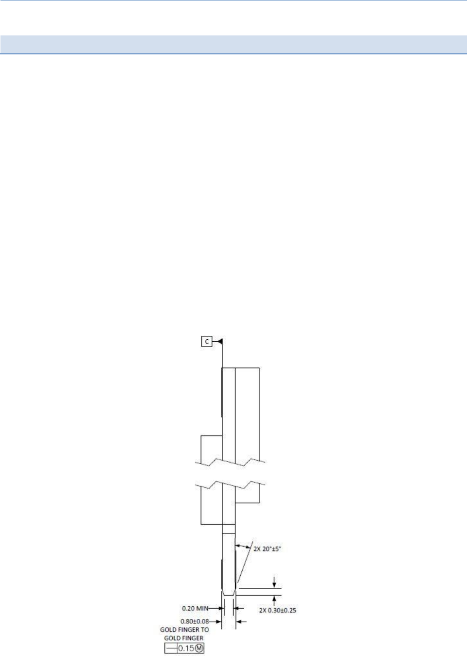
Figure 1 Card Edge Bevel
WISE-1510 User Manual 14
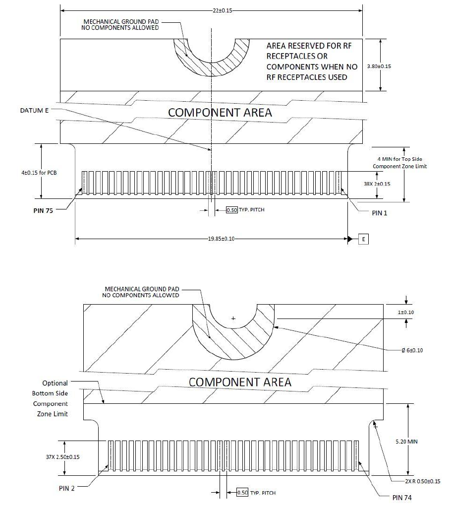
Figure 2 Card Edge Outline-Topside
Figure 3 Card Edge Outline-Backside
Reference from PCI Express M.2 Specification Rev 1.0 (Nov 1, 2013) Section 2.3.5 Card PCB Details
WISE-1510 User Manual 15
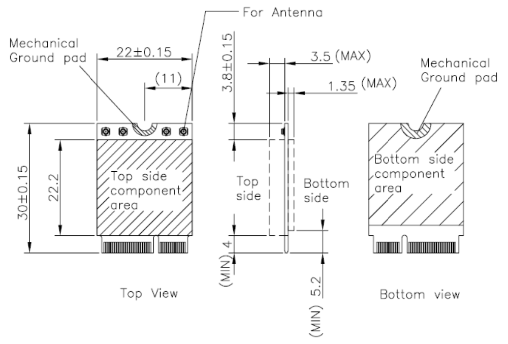
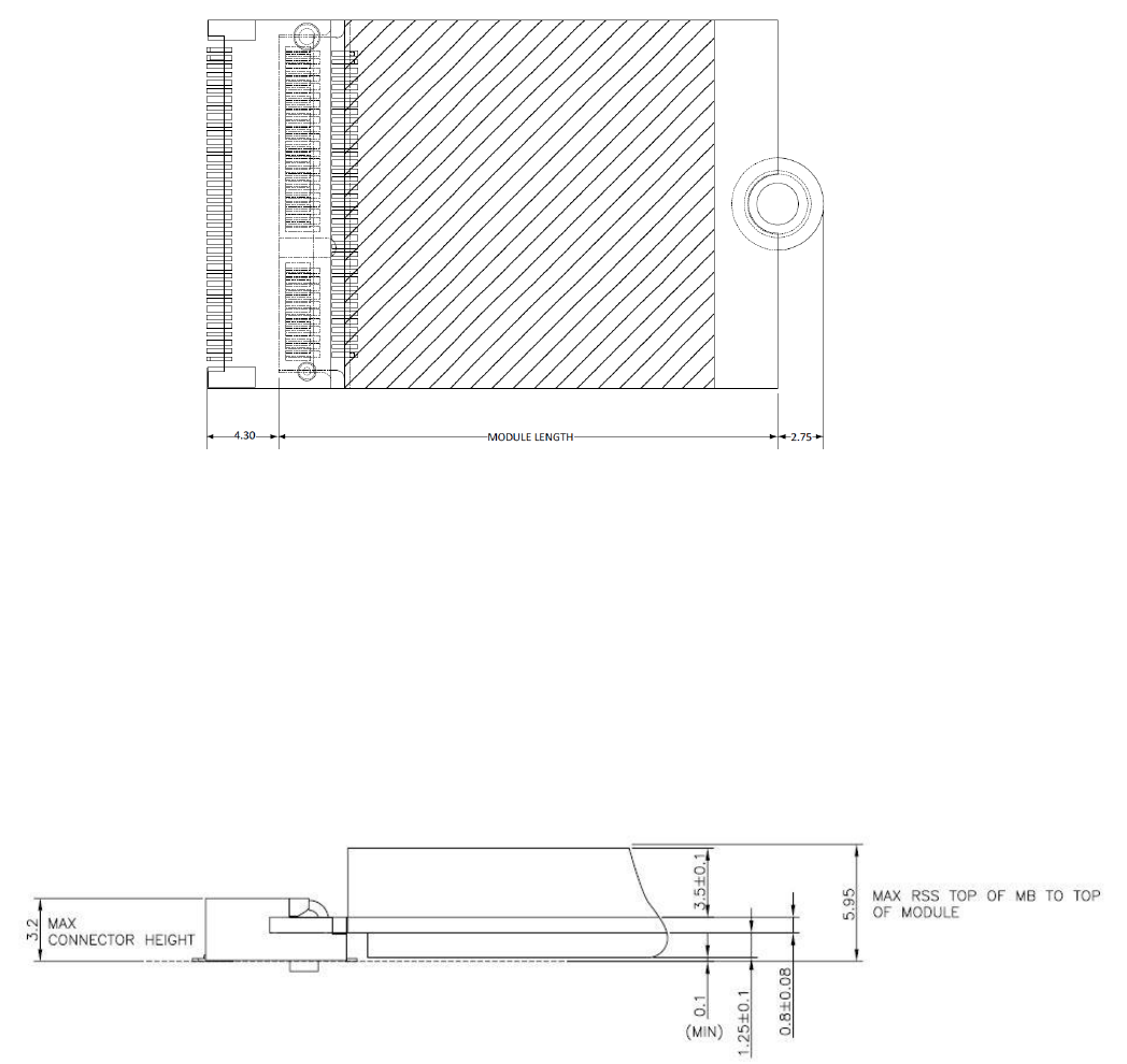
2.2. Module Outline
The mechanical dimension information of M2.COM form factor follows the Type A 2230
module size: 22 x 30 mm. Both module types use a 75-position host interface
connector and have room to support up to four RF connectors in the upper section.
Figure 4 Type A 2230
2.3. Connector Specifications
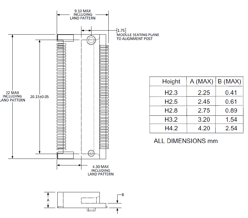
2.3.1. Top Side Connector Physical Dimensions
The top-side scheme has two connectors that share a common footprint but have
different stack-up requirements.
Length – 22 mm maximum including land pattern
Width – 9.1 mm maximum including land pattern
WISE-1510 User Manual 16
Figure 5 Top Side Connector Physical Dimensions
Reference from PCI Express M.2 Specification, Revision 1.0, November 1, 2013
2.3.2. Carrier Board Connection Length
The carrier board connector of M2.COM follows the Type 2230 M.2 module connector:
The additional increase in length is 7.05mm maximum for top-side connector to
the module length.
The retention screw adds 2.75 mm maximum.
The maximum extension, including land pattern, beyond the module leading
edge is 4.3 mm.
M2.COM module lengths are 30 mm and 42 mm.
WISE-1510 User Manual 17
Figure 6 Carrier Board Connection Length
Reference from PCI Express M.2 Specification, Revision 1.0, November 1, 2013
2.3.3. Carrier Board Connector Height
The dimensions of M2.COM form factor follow the Type A 2230 -D3 M.2 module size.
Hence, the carrier board connectors must choose H3.2-D3 or H4.2-D5 connector as in
the following diagrams.
Figure 7 H3.2-D3
Reference from PCI Express M.2 Specification, Revision 1.0, November 1, 2013

WISE-1510 User Manual 18
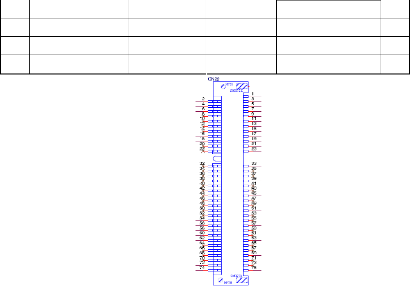
2.4. WISE-1510 Pin-Out Map
PIN
M2.COM
Signal name
STM32L443RCI6
MCU Pin Name
M2.COM
Signal name
PIN
1
GND
GND
3.3V
VCC
2
3
USB_DP
PA12
3.3V
VCC
4
5
USB_DM
PA11
N.C.
6
7
GND
GND
N.C.
8
9
N.C.
N.C.
10
11
N.C.
N.C.
12
13
N.C.
N.C.
14
15
N.C.
PC6
CB_RESET_OUT#
16
17
N.C.
GND
GND
18
19
N.C.
PC9
CB_PWR_ON
20
21
N.C.
PC4
UART TX (O)
22
23
N.C.
Connector Key
Connector Key
Connector Key
Connector Key
Connector Key
Connector Key
Connector Key
Connector Key
PB11
UART RX (I)
32
33
GND
GND
PB1
UART RTS (O)
34
35
N.C.
PB13
UART CTS (I)
36
37
N.C.
PA8
GPIO0
38
39
GND
GND
PC8
GPIO1
40
41
PWM0
PA5
PC7
GPIO2
42
43
N.C.
PC5
GPIO3
44
45
GND
GND
PB0
GPIO4
46
47
ADC0
PA7
PA3
GPIO5
48
49
N.C.
PA2
GPIO6
50
51
GND
GND
PB6
GPIO7
52
53
ADC2
PA6
N.C.
54
55
ADC3
PA4
PC2
W_DISABLE#
56
57
GND
GND
PC1
I2C_DATA
58
59
ADC4
PA0
PC0
I2C_CLK
60
61
N.C.
PB15
SPI_MOSI
62
63
GND
GND
PB14
SPI_MISO
64
65
VDD_RTC
VBAT(3.3V)
PB10
SPI_CLK
66
67
Backup#
PA1
PB12
SPI_CS0#
68
WISE-1510 User Manual 19
69
GND
GND
PB9
SPI_CS1#
70
71
RESET_IN#
NRST
3.3V
VCC
72
73
Wake#
PC3
3.3V
VCC
74
75
GND
GND
Figure 8 M.2 Connector
2.5. Quick Starter of WISE-1510
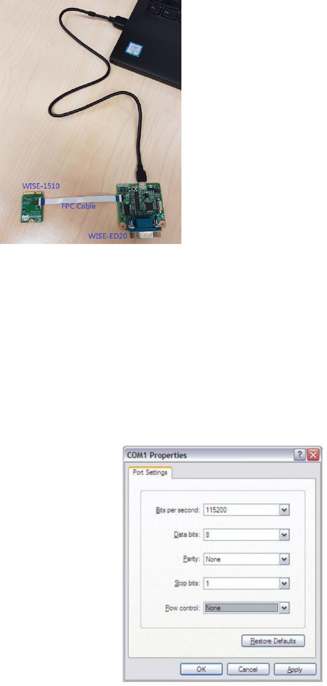
2.5.1. Debug Port Connection
1. Connect debug port FPC cable to WISE-1510 debug port (CN1; on the back of
PCB)
2. Connect WISE-ED20 debug board to the FPC debug cable.
3. Connect USB-to-microUSB cable from WISE-ED20 to the USB port on your PC.
WISE-1510 User Manual 20
2.5.2. Debug Port Setting
WISE-1510 can communicate with a host server (Windows or Linux) by using serial
cables. Common serial communication programs such as Hyper Terminal, Tera Term
or PuTTY can be used in this case. The example below describes the serial terminal
setup using Hyper Terminal on a Windows host:
1. Connect WISE-ED20 with your Windows PC by using a serial cable.
2. Open Hyper Terminal on your Windows PC, and select the settings as shown in
Figure 9.
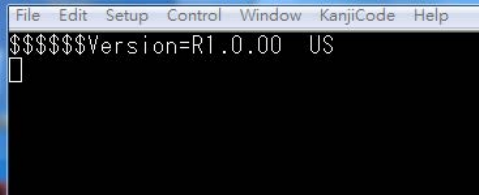
3. Terminal will show the image version as Figure 10.
WISE-1510 User Manual 21
Figure 9 Hyper Terminal Settings for Terminal Setup
Figure 10 Image version is shown on terminal

WISE-1510 User Manual 22
3. Development Environment Setup
3.1. Overview
ARM mbed is used for you to create applications running on WISE-1510. Your
application code is written in C++. It uses the application programming interfaces
(APIs) that mbed OS provides. These APIs allow your code to work on different
microcontrollers in a uniform way. This reduces a lot of the challenges in getting
started with microcontrollers and integrating large amounts of software. Besides, we
also provide you node APIs which facilitates LoRa node development. Our offline
development tool is the mbed CLI, a command-line tool. This requires having a
toolchain installed on your computer. mbed CLI is the name of the ARM mbed
command-line tool, packaged as mbed-cli, which enables the full mbed workflow:
repositories version control, maintaining dependencies, publishing code, updating
from remotely hosted repositories and invoking ARM mbed’s own build system and
export functions, among other operations. The basic workflow for mbed CLI is to:
1. Initialize a new repository, for either a new application (or library) or an imported
one.
2. Build the application code.
3. Test your build.
4. Publish your application.
3.2. Installation
To install mbed CLI, related tools are required to be installed first. Please refer to the
video tutorial. ( https://www.youtube.com/watch?v=cM0dFoTuU14 )
Please follow the steps described in the tutorial video to install mbed CLI.
1. Install Python
mbed CLI supports Windows, Linux and Mac OS X operating systems. You can select
the OS you prefer to work with. mbed CLI is a Python script, so you’ll need Python to
use it. The version 2.7.11 of Python has been verified with mbed CLI.
https://www.python.org/downloads/release/python-2711/
Note: mbed CLI is incompatible with Python 3.
2. (Optional) Install Git or Mercurial
If you would like to maintain your source code in repositories, you can continue
with the next step. mbed CLI supports both Git and Mercurial repositories, you can
install which one you prefer:

WISE-1510 User Manual 23
Git - version 1.9.5 or later ( https://git-scm.com/ ).
Mercurial - version 2.2.2 or later ( https://www.mercurial-scm.org/ ).
If you don’t want to use repositories, you can just skip it.
3. Install gcc
mbed CLI invokes the mbed OS 5 tools for various features, such as compiling,
testing and exporting to industry standard toolchains. To compile your code, you will
need either a compiler or an IDE:
Compilers: GCC ARM, ARM Compiler 5, IAR.
IDE: Keil uVision, DS-5, IAR Workbench.
We select GCC ARM Embedded, so you can install version 4.9 of GCC ARM
Embedded ( https://launchpad.net/gcc-arm-embedded ).
Note: Version 5.0 or any other versions above may be incompatible with the tools.
4. Install mbed CLI
You can get the latest stable version of mbed CLI from PyPI
$ pip install mbed-cli
Note: On Linux or Mac, you may need to run with sudo.
Finally, you’ve to extract the source code to the working directory from the SDK we
released. The structure of the working directory is as below:
docs/ <-- Documents for SDK
loranode_L443_sdk_R1_0_02/mbed-os/ <-- mbed os
loranode_L443_sdk_R1_0_02/libHLLoraNode.a <-- Harmony Link Lora
Node library
loranode_L443_sdk_R1_0_02/node_api.h <-- Node API header file
loranode_L443_sdk_R1_0_02/main.cpp <-- Sample code
3.3. Configuration
After the installation of required tool chains, please set up the directory of mbed CLI to
link the folder of toolchains which you want to use for compiling the source tree.
You can set the GCC ARM Embedded location via the command as below:
$ mbed config --global GCC_ARM_PATH "C:\Program Files\GCC_ARM"
[mbed] C:\Program Files\GCC_ARM now set as global GCC_ARM_PATH

WISE-1510 User Manual 24
Next, you can select the tool chain and target platform which mbed CLI uses to build
applications. Change directory to target mbed program.
$ mbed config target NUCLEO_L443RC
[mbed] NUCLEO_L443RC now set as default target in program "xxxxx"
$ mbed config toolchain GCC_ARM
[mbed] GCC_ARM now set as default toolchain in program "xxxx"
You can see the active mbed CLI configuration via:
$ mbed config --list
[mbed] Global config:
GCC_ARM_PATH =C:\Program Files\GCC_ARM
[mbed] Local config (xxxx):
TOOLCHAIN=GCC_ARM
TARGET=NUCLEO_L443RC
3.4. Compilation
mbed CLI uses the current directory as a working context. This means that before
calling any mbed CLI command, you must first change to the working directory
containing the code. Then, Use the mbed compile command to compile your code:
$ mbed compile -c
Building project xxxxx (NUCLEO_L443RC, GCC_ARM)
Scan: .
Scan: mbed
Scan: env
Compile [ 0.5%]: base64.cpp
Compile [ 1.0%]: oslmic.cpp
…
Compile [100.0%]: node_sapi.cpp
Link: xxxxx
Elf2Bin: xxxxx
+--------------------+--------+-------+-------+
| Module | .text | .data | .bss |
+--------------------+--------+-------+-------+
| Fill | 223 | 16 | 41 |
| Misc | 104316 | 7804 | 5017 |
| drivers | 3592 | 4 | 224 |

WISE-1510 User Manual 25
| hal | 802 | 0 | 8 |
| platform | 1782 | 4 | 297 |
| rtos | 910 | 4 | 4 |
| rtos/rtx | 7369 | 20 | 6870 |
| targets/TARGET_STM | 19944 | 4 | 1719 |
| Subtotals | 138938 | 7856 | 14180 |
+--------------------+--------+-------+-------+
Allocated Heap: unknown
Allocated Stack: unknown
Total Static RAM memory (data + bss): 22036 bytes
Total RAM memory (data + bss + heap + stack): 22036 bytes
Total Flash memory (text + data + misc): 146794 bytes
Image: ./BUILD/NUCLEO_L443RC/GCC_ARM/xxxxx.bin
Now, you have your application in binary format ready for flashing.
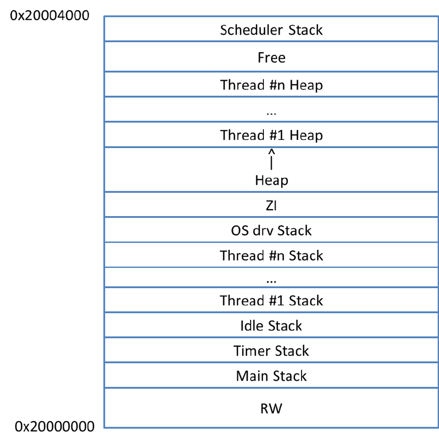
3.5. Memory Layout
A basic overview of mbed memory model is as below:
Each thread of execution in the RTOS has a separate stack. When you use the RTOS,
before explicitly initializing any additional thread, you will have four separate stacks:
• The stack of the main thread (executing the main function).
• The idle thread executed each time all the other threads are waiting for external
or scheduled events. This is particularly useful for implementing energy saving
strategies (like sleep).
• The timer thread that executes all the time-scheduled tasks (periodic and
nonperiodic).
• The stack of OS scheduler itself (also used by the ISRs).
Stack checking is turned on for all threads, and the kernel will error if an overflow
condition is detected.
WISE-1510 User Manual 26
WISE-1510 User Manual 27
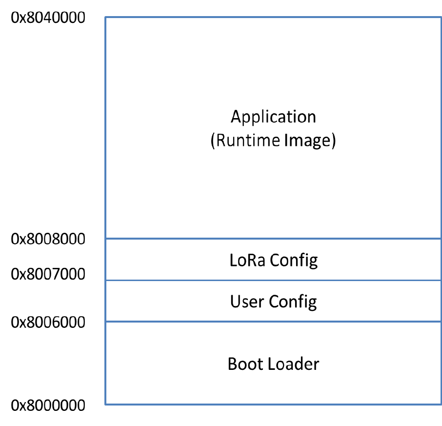
3.6. Partitioning
The content of flash is portioned by boot loader as below:
Boot Loader occupies the first 16 kilo-bytes starting at 0x8000000. LoRa Config
partition is used to store LoRa parameters, which occupies no more than 4 kilo-bytes.
All user own parameters should be written into User Config partition, for which another
4 kilo-bytes are reserved. Application (Runtime image) partition is where users’
application is stored, up to 224 kilo-bytes can be used.
WISE-1510 User Manual 28
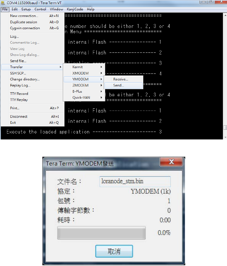
3.7. Flashing Application (Runtime Image)
To flash runtime image, your terminal program needs to support “Y-Modem”.
Tera Term is used for demonstration here.
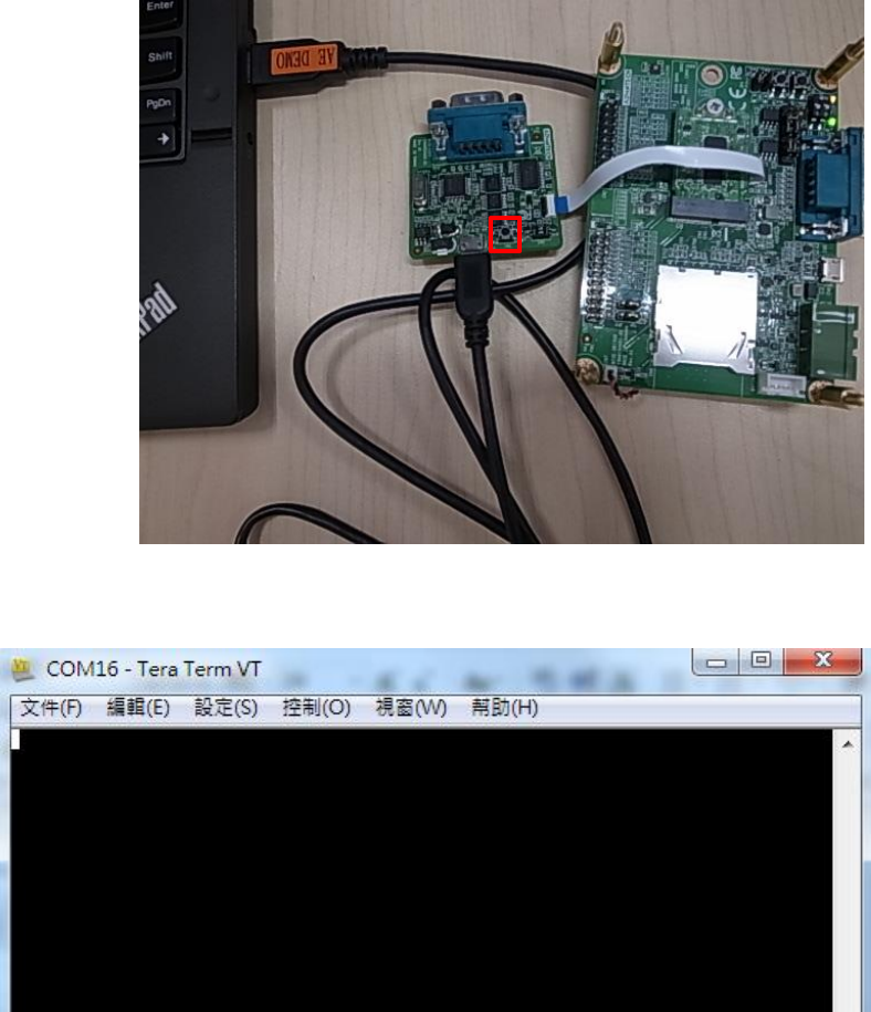
Step 1: UART port connect via debug board
Connect USB-to-microUSB cable from WISE-ED20 to the USB port on your Windows
PC. (Red frame is reset button.)
Open the corresponding COM port in serial program, ex: Tera Term.
Set baud rate to 115200.
WISE-1510 User Manual 29
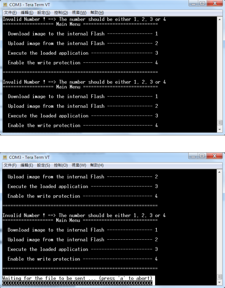
Step 2: Runtime image upgrade mode
Press ‘u’ on the PC keyboard and press reset button on ED-20 debug board.
The terminal will show messages as below.
Press "1" to “Download image to the internal Flash”.
WISE-1510 User Manual 30
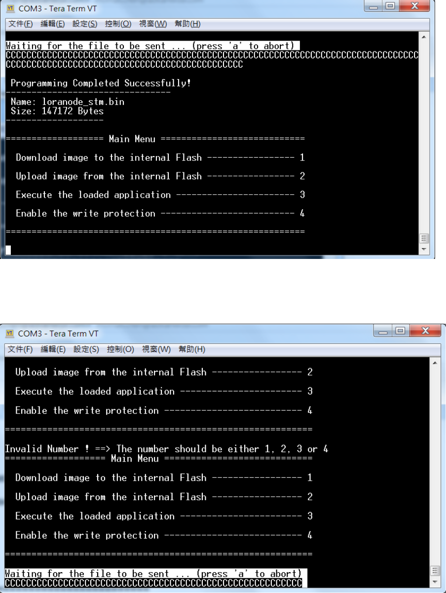
Step 3: Start upgrading via Y modem
Select the run-time image ".bin" file via Y-Modem.
Waiting for run-time image transmission is complete.
WISE-1510 User Manual 31
After downloading completed, the terminal will show as below.
Step 4: Reset device
Press reset button on ED-20 debug board to reset device.
WISE-1510 User Manual 32
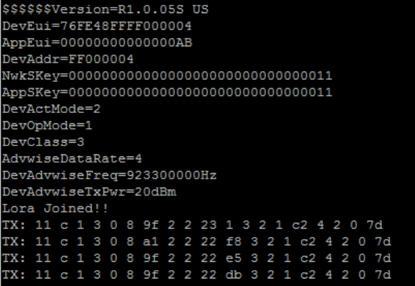
3.8. Testing
Now, you’re ready to test your WISE-1510. The sample application we created is to
send sensor data every 5 seconds via LoRa if values are changed. To observe it, you
can connect the debug port as described earlier. After reset WISE-1510, the result is
shown on your Terminal as below:
WISE-1510 User Manual 33
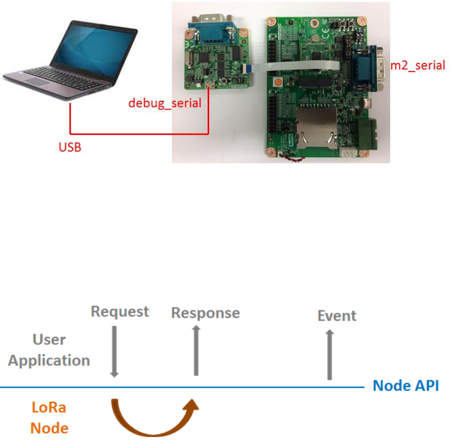
4. Application Development
Node APIs were provided to assist user develop applications. There are 2 UART
interfaces in WISE-1510. “debug_serial” is used for user development and debug.
User can see debug information of sample code via debug_serial. “m2_serial” is the
UART interface of M2.com.
4.1. Node API
Following show the architecture of the layer of LoRa Node and user application. User
can send request to LoRa node via API and got response. Besides, application can
also be notified by callback function if some event occurs from LoRa node.
Node APIs were listed as below:
System Start/reboot
nodeApiInitCarrierBoard
nodeApiStartLora
nodeApiReboot
Configuration get/set/save/factory reset
WISE-1510 User Manual 34
nodeApiGetDevEui
nodeApiGetAppEui
nodeApiGetAppKey
nodeApiGetDevAddr
nodeApiGetNwkSKey
nodeApiGetAppSKey
nodeApiGetDevActMode
nodeApiGetDevOpMode
nodeApiGetDevAdvwiseFreq
nodeApiGetDevAdvwiseDataRate
nodeApiGetDevAdvwiseTxPwr
nodeApiSetDevEui
nodeApiSetAppEui
nodeApiSetAppKey
nodeApiSetDevAddr
nodeApiSetNwkSKey
nodeApiSetAppSKey
nodeApiSetDevActMode
nodeApiSetDevOpMode
nodeApiSetDevAdvwiseFreq
nodeApiSetDevAdvwiseDataRate
nodeApiSetDevAdvwiseTxPwr
nodeApiSaveCfg
nodeApiLoadCfg
nodeApiApplyCfg
nodeApiFactoryReset
LoRa callback function register/status check/send data
nodeApiSetTxDoneCb
nodeApiSetRxDoneCb
nodeApiJoinState
nodeApiSendData
System deep sleep (low power) mode
WISE-1510 User Manual 35
nodeApiSetDevSleepRTCWakeup
The detailed description of APIs can be found in /docs/html/index.html in the released
SDK.
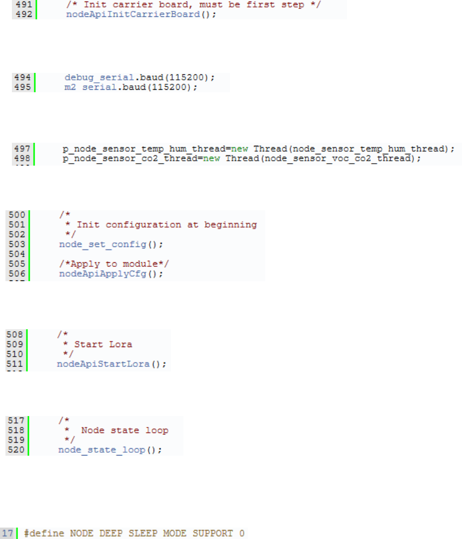
4.2. Sample Code for API
If WISE-1510 was plugged in M2.com carrier board (WISE-DB1500), do below action
to enable M2.com carrier board.
Set boud rate of debug_serial and m2_serial.
Create sensor thread.
Set and apply node configuration.
Start LoRa.
Start LoRa State loop to start rx/tx data.
Deep sleep mode is supported but disabled in default, please enable
NODE_DEEP_SLEEP_MODE_SUPPORT if you want to try low power mode.
WISE-1510 User Manual 36
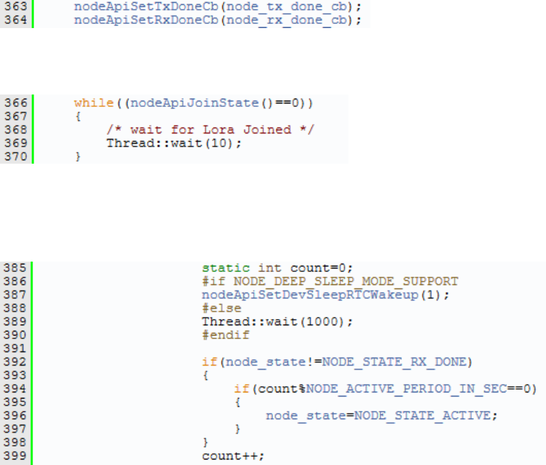
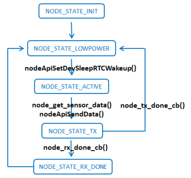
2 API were used to notify user application that LoRa finished transmit or receive
action. What you should do is Register callback function in the beginning.
Make sure node successfully joined LoRa gateway.
Then, start to run the state machine. If no data need to send, enter deep sleep
mode and wait for waking up NODE_ACTIVE_PERIOD_IN_SEC seconds.
This example send sensor (Temperature, Humidity) data periodically, user should
modify node_get_sensor_data() to implement read sensor data.
If Tx complete, node_tx_done_cb() will transfer to NODE_STATE_LOWPOWER
and prepare to read/send sensor data again.
If LoRa node got downlink data, node_rx_done_cb() will be invoked to get data.
Then transfer to NODE_STATE_LOWPOWER.
WISE-1510 User Manual 37
The detailed description of Sample code can be found in /docs/html/index.html in the
released SDK.
WISE-1510 User Manual 38
Appendix I: Node Setup Parameters
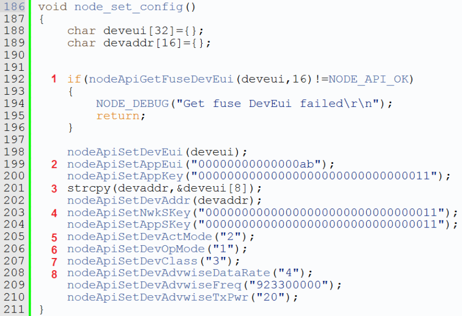
In the sample application, there is a function node_set_config() as below:
This function is used to configure all parameters of nodes. Let’s go through them
briefly.
1. Device EUI (DevEUI) is read from eFuse, and set without any change.
2. Two application dependent parameters, application EUI (AppEUI) and application
key (APPKey), are set respectively (line 218 and 219).
3. Device address (DevAddr) is derived from DevEUI by extracting the last 8 bytes
(line 220), and set (line 221). It’s up to users to define the format as long as it
matches with gateway’s setting.
4. Two session keys: network session key (NwkSKey) and application session key
(AppSKey) are set (line 222 and 223).
5. So far, all required parameters for node activation are set properly. Then, you can
decide to activate the node by either ABP (Activation By Provisioning) or OTAA
(Over-The-Air Activation). Here, we set it to ABP (line 224). Please be noted that,
only three of the above parameters are used for ABP, including DevAddr,
NwkSKey and AppSKey. If you’d like to use OTAA, then change the input
parameter of nodeApiSetDevActMode() from 2 to 1. The other three parameters
are used for OTAA, including DevEUI, AppEUI, and APPKey are set.
6. Select nodes to work with LoRaWAN or Harmony Link by setting the device
WISE-1510 User Manual 39
operating mode (DevOpMode): 1 for Harmony Link* and 2 for LoRaWAN. Here,
Harmony Link is selected as the default. (line 225) If you’d like to use LoRaWAN,
change it from 1 to 2.
* Harmony Link is Advantech’s proprietary LoRa MAC.
7. You can select which class of Node: 1 for Class A, and 3 for Class C. (2 for Class B
is reserved for future use.) Here, Class C is selected (line 226).
8. The remaining part are used to set radio related parameters, including data rate
(DevAdvwiseDataRate), frequency (DevAdvwiseFreq) and transmission power
(DevAdvwiseTxPwr) (line 227~229). Please be noted all of RF parameters are
region dependent, so you’ve to set their values accordingly. Make sure you DO
NOT violate the regional regulation.
After all parameters are configured, be reminded to apply them by nodeApiApplyCfg().
WISE-1510 User Manual 40
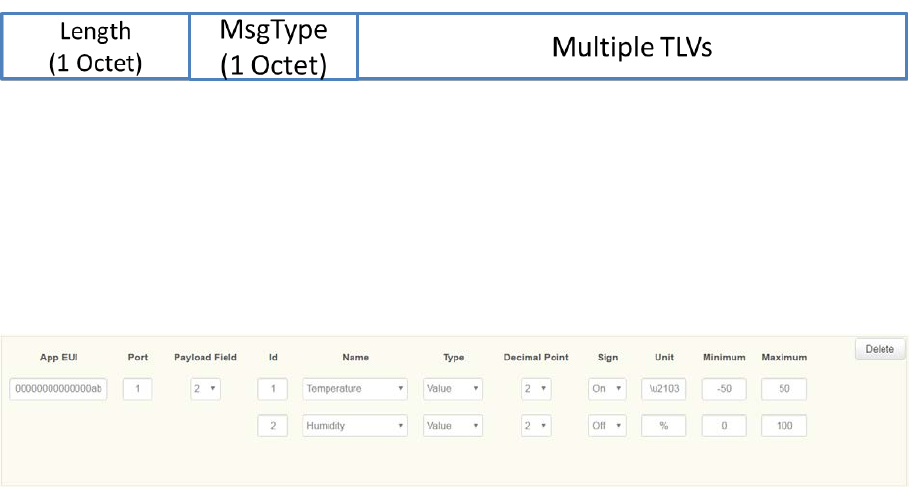
Appendix II: Sensor Data Format
In the sample application, node_get_sensor_data() encodes sensor data according to
the following format:
,where
Length: Total TLV length
MsgType: Fixed as 0xc
Multiple TLVs are one or more Tag-Length-Values: tag matches with gateway’s setting,
length is sensor data length, and value is sensor data. All octets are in hexadecimal.
For example, LoRa Payload Field setting on WISE-3610 is as below:
If temperature is 25.55 Celsius degree, translate decimal 2555 to hexadecimal 9FB.
Similarly, if humidity is 60.55%, translate from decimal 6055 to hexadecimal 17A7.
The encoded data will be
0x9 | 0xc | 0x1 | 0x3 | 0x1 | 0x9 | 0xFB | 0x2 | 0x2 | 0x17 | 0xA7
, where
0x9: the Total TLV length, included two TLVs
0xc: the fixed MsgType
0x1 | 0x3 | 0x1 | 0x9 | 0xFB: the first TLV with tag id (0x1), value length (0x3), and
positive (0x1) value (0x9FB)
0x2 | 0x2 | 0x17 | 0xA7: the second TLV with tag id (0x2), value length (0x2), and
unsigned value (0x17A7)
Be reminded temperature “Sign” setting is On, 1 extra byte is required to indicate (0
means negative, and 1 means positive) , but humidity "Sign" setting on gateway is Off,
so no extra 1 byte is required.
Users are free to define their own payload field format, but only sensor data encoded
according to the above format can be decoded successfully, and displayed on LoRa
Dashboard on WISE-3610.