Advantech Co WISE3610 IoT Gateway User Manual Quick Start Guide
Advantech Co Ltd IoT Gateway Quick Start Guide
UserManual.wiki
>
Advantech Co
>
WISE3610 User Manual
Users Manual_rev 2.pdf
Navigation menu
Upload a User Manual
Namespaces
Wiki Guide
HTML
PDF
Info
Views
User Manual
Discussion / Help
Navigation
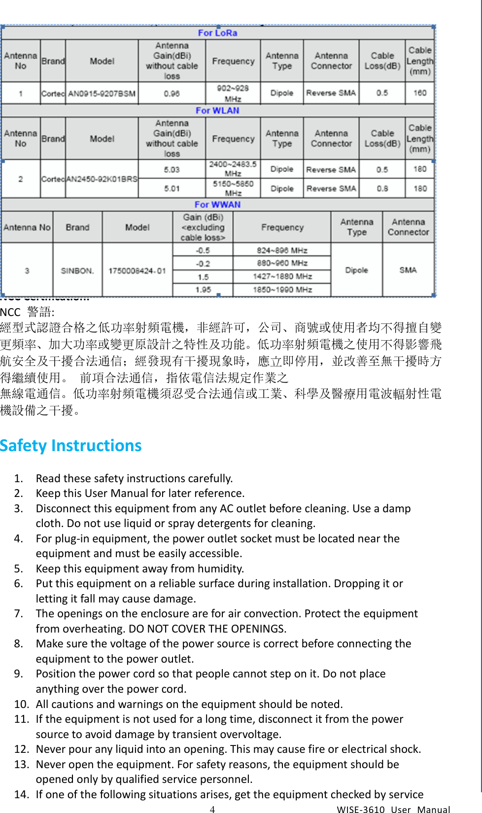
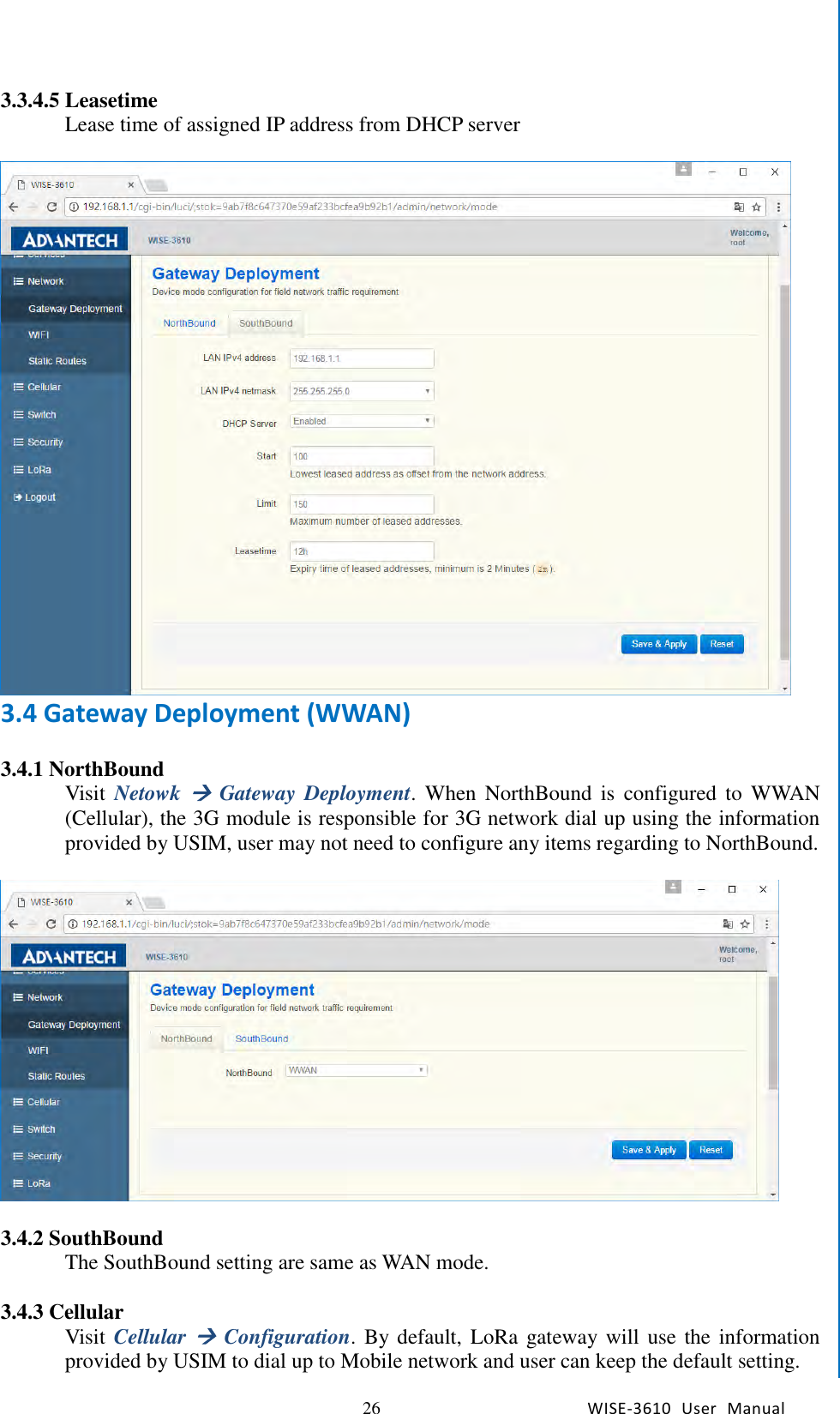
![3 WISE-3610 User Manual Chapter1 General Introduction (ii) the maximum antenna gain permitted for devices in the band 5725-5850 MHz shall be such that the equipment still complies with the e.i.r.p. limits specified for point-to-point and non-point-to-point operation as appropriate; and (iii) Users should also be advised that high-power radars are allocated as primary users (i.e. priority users) of the bands 5650-5850 MHz and that these radars could cause interference and/or damage to LE-LAN devices. Avertissement: (i) les dispositifs fonctionnant dans la bande 5150-5250 MHz sont réservés uniquement pour une utilisation à l’intérieur afin de réduire les risques de brouillage préjudiciable aux systèmes de satellites mobiles utilisant les mêmes canaux; (ii) le gain maximal d'antenne permis (pour les dispositifs utilisant la bande de 5725 à 5 850 MHz) doit être conforme à la limite de la p.i.r.e. spécifiée pour l'exploitation point à point et l’exploitation non point à point, selon le cas; (iii) De plus, les utilisateurs devraient aussi être avisés que les utilisateurs de radars de haute puissance sont désignés utilisateurs principaux (c.-à-d., qu’ils ont la priorité) pour les bandes 5650-5850 MHz et que ces radars pourraient causer du brouillage et/ou des dommages aux dispositifs LAN-EL. Radiation Exposure Statement: This equipment complies with ISED radiation exposure limits set forth for an uncontrolled environment. This equipment should be installed and operated with minimum distance 44 between the radiator & your body. Déclaration d'exposition aux radiations: Cet équipement est conforme aux limites d'exposition aux rayonnements ISED établies pour un environnement non contrôlé. Cet équipement doit être installé et utilisé avec un minimum de 44m de distance entre la source de rayonnement et votre corps. CE This device complies with Directive 2014/53/EU issued by the Commission of the European Community. Declaration of Conformity Hereby, [Advantech Co., Ltd.] declares that the radio equipment type [designation of type of radio equipment] is in compliance with Directive 2014/53/EU. The full text of the EU declaration of conformity is available at the following internet address: The frequency and maximum transmitted power in EU are listed as belows, 2412 - 2472 MHz: XX.XX dBM 5180 - 5240 MHz: XX.XX dBM 5260 - 5230 MHz: XX.XX dBM 5500 - 5700 MHz: XX.XX dBM - WLAN 5GHz: Operations in the 5.15-5.35GHz band are restricted to indoor usage only. Déclaration d'exposition aux radiations: Cet équipement est conforme aux limites d'exposition aux rayonnements ISED établies pour un environnement non contrôlé. Cet équipement doit être installé et utilisé avec un minimum de 44m de distance entre la source de rayonnement et votre corps. This radio transmitter (IC: IC: 9404A-WISE3610 / Model: WISE-3610) has been approved by ISED to operate with the antenna type listed below with maximum permissible gain indicated. Antenna types not included in this list, having a gain greater than the maximum gain indicated for that type, are strictly prohibited for use with this device. Le présent émetteur radio (IC: IC: 9404A-WISE3610 / Model: WISE-3610) a été approuvé par ISED pour fonctionner avec les types d'antenne énumérés ci-dessous et ayant un gain admissible maximal. Les types d'antenne non inclus dans cette liste, et dont le gain est supérieur au gain maximal indiqué, sont strictement interdits pour l'exploitation de l'émetteur.](https://usermanual.wiki/Advantech-Co/WISE3610/User-Guide-3607626-Page-4.png)


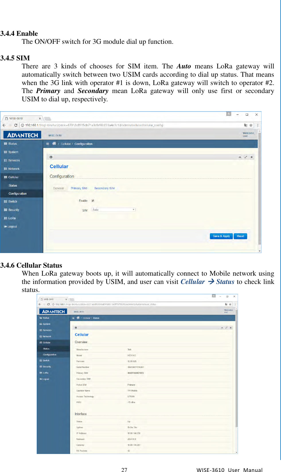
![66 WISE-3610 User Manual Chapter5 Advantech Services 3.27 LoRa Node Import Visit WISE Manageer->Node Import to import node database. Click on the “Node.json” after “Template” to download the database template. The content of Node.json is as below: [ { "Metadata" : ["DevEUI", "AppEUI", "Class", "ActMode", "AppKey", "PayloadField", "SpsConf", "Remark"], "Node" : [ ["76FE48FFFA000001", "00000000000000ab", "C", "OTAA", "000000000000000000000000000000A1", "1", "1", "Node1"], ["76FE48FFFA000002", "00000000000000ab", "A", "OTAA", "000000000000000000000000000000A2", "1", "1", "Node2"] ] }, { "Metadata" : ["DevEUI", "AppEUI", "Class", "ActMode", "DevAddr", "NwkSKey", "AppSKey", "PayloadField", "SpsConf", "Remark"], "Node" : [ ["76FE48FFFA000003", "00000000000000ab", "A", "ABP", "FA000003", "000000000000000000000000000000A3", "000000000000000000000000000000A3", "1", "1", "Node3"], ["76FE48FFFA000004", "00000000000000ab", "C", "ABP", "FA000004", "000000000000000000000000000000A4", "000000000000000000000000000000A4", "1", "1", "Node4"] ] } ]](https://usermanual.wiki/Advantech-Co/WISE3610/User-Guide-3607626-Page-72.png)