Advantech Co WISE4220 IoT Wireless Sensor Node User Manual V4 12 EA User Manual
Advantech Co Ltd IoT Wireless Sensor Node V4 12 EA User Manual
UserManual.wiki
>
Advantech Co
>
WISE4220 User Manual
Users Manual.pdf
Navigation menu
Upload a User Manual
Namespaces
Wiki Guide
HTML
PDF
Info
Views
User Manual
Discussion / Help
Navigation


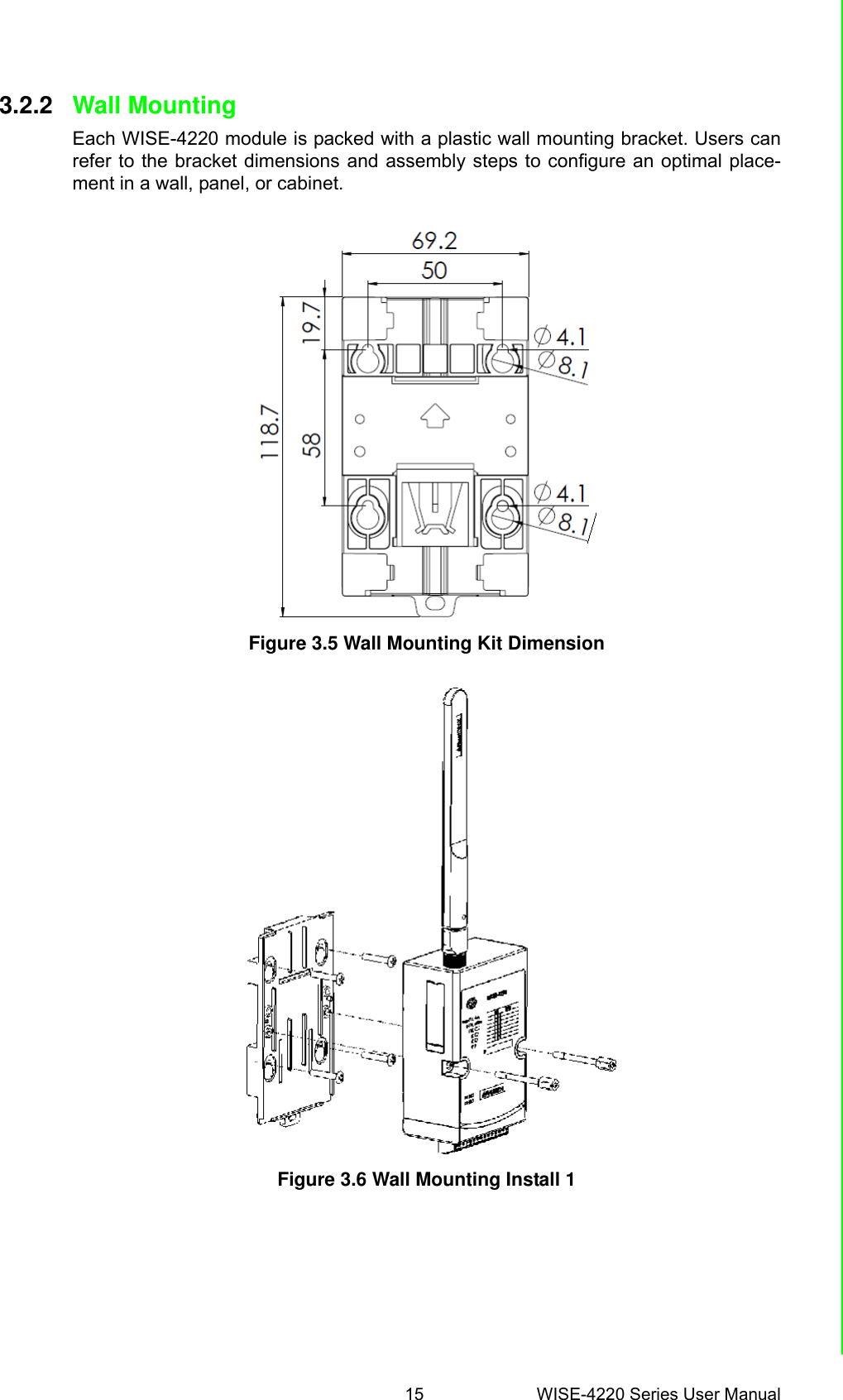


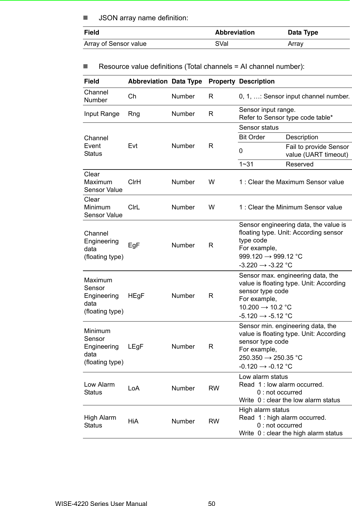
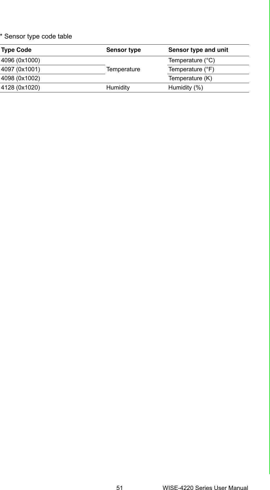
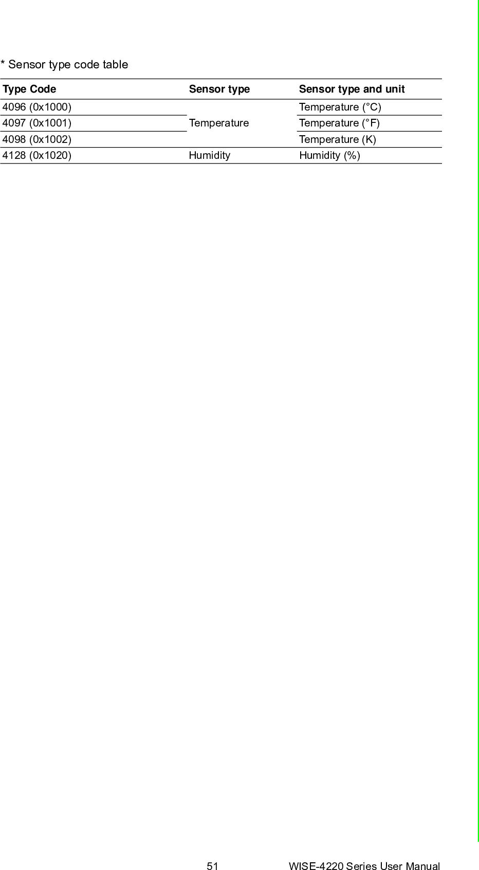
![WISE-4220 Series User Manual 48B.1 IntroductionRepresentational State Transfer (REST) is a software architecture for how web appli-cations and services interact encompassing every thing or entity that can be identi-fied, named, addressed or handled, in any way whatsoever, on the Web. It can bedeveloped with compatible popular protocols or standards like HTTP, URI, JSON,HTML. With the advantage of scalability, simplicity and performance, it's alreadyadopted by Amazon and Yahoo web services. The web service is developed basedon HTML5 language, if a user need to integrate this into other web services, the fol-lowing information/command list can be referenced.B.2 REST Resources for WISE-4220 SeriesB.2.1 Sensor Input/sensor_value/slot_0/ch_numDescription Retrieves information about the sensor input value resource on specific slot.URL Structurehttp://10.0.0.1/sensor_value/slot_0http://10.0.0.1/sensor_value/slot_0/ch_numwhere num = 0 ~ : the channel numberHTTP MethodGET: Returns the representation of all of analog input value resource.PUT: NonePATCH: Apply partial modifications to analog input value resource.GET Multi Channel Request: GET /sensor_value/slot_0Single Channel Request: GET /sensor_value/slot_0/ch_num[Example]Request: GET /sensor_value/slot_0Content-type: application/jsonResponse: 200 OK{ "SVal": [ { "Ch":0, "Rng":4096, "EgF":0.650, "HEgF":1.250, "LEgF":0.500, "Evt":0, “LoA”: 0, “HiA”: 0 "ClrH": 0, "ClrL": 0, }, { "Ch":1, "Rng":4128, "EgF":0.000, "HEgF":0.000, "LEgF":0.000, "Evt":0,](https://usermanual.wiki/Advantech-Co/WISE4220/User-Guide-3575251-Page-58.png)
![49 WISE-4220 Series User ManualAppendix B REST for WISE-4220 Series “LoA”: 0, “HiA”: 0 "ClrH": 0, "ClrL": 0 } ]}Request: GET /sensor_value/slot_0/ch_1Content-type: application/jsonResponse: 200 OK{ "Ch":1, "Rng":4128, "Evt":0, "EgF":0.000, "HEgF":0.000, "LEgF":0.000, “LoA”: 0, “HiA”: 0 "ClrH": 0, "ClrL": 0}PUT NonePATCHSingle/Multi Channel Request: PATCH /sensor_value/slot_0Single Channel Request: PATCH /sensor_value/slot_0/ch_num[Example]Request: PATCH /sensor_value/slot_0Content-type: application/json{" SVal": [ { "Ch":0, "ClrH": 0 }, { "Ch":1, "ClrL":0 } ]}Response: 200 OKRequest: PATCH /sensor_value/slot_0/ch_1Content-type: application/json{ "ClrL":0}Response: 200 OK](https://usermanual.wiki/Advantech-Co/WISE4220/User-Guide-3575251-Page-59.png)