Advantech Co WISE4220 IoT Wireless Sensor Node User Manual V4 12 EA User Manual
Advantech Co Ltd IoT Wireless Sensor Node V4 12 EA User Manual
Users Manual.pdf

User Manual
WISE-4220 Series
Model on: WISE4220

WISE-4220 Series User Manual ii
Copyright
The documentation and the software included with this product are copyrighted 2017
by Advantech Co., Ltd. All rights are reserved. Advantech Co., Ltd. reserves the right
to make improvements in the products described in this manual at any time without
notice. No part of this manual may be reproduced, copied, translated or transmitted
in any form or by any means without the prior written permission of Advantech Co.,
Ltd. Information provided in this manual is intended to be accurate and reliable. How-
ever, Advantech Co., Ltd. assumes no responsibility for its use, nor for any infringe-
ments of the rights of third parties, which may result from its use.
Acknowledgements
Intel and Pentium are trademarks of Intel Corporation.
Microsoft Windows and MS-DOS are registered trademarks of Microsoft Corp.
All other product names or trademarks are properties of their respective owners.
Product Warranty (2 years)
Advantech warrants to you, the original purchaser, that each of its products will be
free from defects in materials and workmanship for two years from the date of pur-
chase.
This warranty does not apply to any products which have been repaired or altered by
persons other than repair personnel authorized by Advantech, or which have been
subject to misuse, abuse, accident or improper installation. Advantech assumes no
liability under the terms of this warranty as a consequence of such events.
Because of Advantech’s high quality-control standards and rigorous testing, most of
our customers never need to use our repair service. If an Advantech product is defec-
tive, it will be repaired or replaced at no charge during the warranty period. For out-
of-warranty repairs, you will be billed according to the cost of replacement materials,
service time and freight. Please consult your dealer for more details.
If you think you have a defective product, follow these steps:
1. Collect all the information about the problem encountered. (For example, CPU
speed, Advantech products used, other hardware and software used, etc.) Note
anything abnormal and list any onscreen messages you get when the problem
occurs.
2. Call your dealer and describe the problem. Please have your manual, product,
and any helpful information readily available.
3. If your product is diagnosed as defective, obtain an RMA (return merchandize
authorization) number from your dealer. This allows us to process your return
more quickly.
4. Carefully pack the defective product, a fully-completed Repair and Replacement
Order Card and a photocopy proof of purchase date (such as your sales receipt)
in a shippable container. A product returned without proof of the purchase date
is not eligible for warranty service.
5. Write the RMA number visibly on the outside of the package and ship it prepaid
to your dealer.
Part No. 2003422021 Edition 2
Printed in Taiwan September 2017

iii WISE-4220 Series User Manual
Declaration of Conformity
CE
This product has passed the CE test for environmental specifications. Test conditions
for passing included the equipment being operated within an industrial enclosure. In
order to protect the product from being damaged by ESD (Electrostatic Discharge)
and EMI leakage, we strongly recommend the use of CE-compliant industrial enclo-
sure products.
FCC Class A
Note: This equipment has been tested and found to comply with the limits for a Class
A digital device, pursuant to part 15 of the FCC Rules. These limits are designed to
provide reasonable protection against harmful interference when the equipment is
operated in a commercial environment. This equipment generates, uses, and can
radiate radio frequency energy and, if not installed and used in accordance with the
instruction manual, may cause harmful interference to radio communications. Opera-
tion of this equipment in a residential area is likely to cause harmful interference in
which case the user will be required to correct the interference at his own expense.
Technical Support and Assistance
1. Visit the Advantech web site at www.advantech.com/support where you can find
the latest information about the product.
2. Contact your distributor, sales representative, or Advantech's customer service
center for technical support if you need additional assistance. Please have the
following information ready before you call:
–Product name and serial number
–Description of your peripheral attachments
–Description of your software (operating system, version, application software,
etc.)
–A complete description of the problem
–The exact wording of any error messages

WISE-4220 Series User Manual iv
Warnings, Cautions and Notes
Document Feedback
To assist us in making improvements to this manual, we would welcome comments
and constructive criticism. Please send all such - in writing to: support@advan-
tech.com
Package List
Before setting up the system, check that the items listed below are included and in
good condition. If any item does not accord with the table, please contact your dealer
immediately. Please go to Section 1.6 for package list.
Warning! Warnings indicate conditions, which if not observed, can cause personal
injury!
Caution! Cautions are included to help you avoid damaging hardware or losing
data. e.g.There is a danger of a new battery exploding if it is incorrectly
installed. Do not attempt to recharge, force open, or heat the battery.
Replace the battery only with the same or equivalent type recom-
mended by the manufacturer. Discard used batteries according to the
manufacturer's instructions.
Note! Notes provide optional additional information.

v WISE-4220 Series User Manual
Safety Instructions
1. Read these safety instructions carefully.
2. Keep this User Manual for later reference.
3. Disconnect this equipment from any AC outlet before cleaning. Use a damp
cloth. Do not use liquid or spray detergents for cleaning.
4. For plug-in equipment, the power outlet socket must be located near the equip-
ment and must be easily accessible.
5. Keep this equipment away from humidity.
6. Put this equipment on a reliable surface during installation. Dropping it or letting
it fall may cause damage.
7. The openings on the enclosure are for air convection. Protect the equipment
from overheating. DO NOT COVER THE OPENINGS.
8. Make sure the voltage of the power source is correct before connecting the
equipment to the power outlet.
9. Position the power cord so that people cannot step on it. Do not place anything
over the power cord.
10. All cautions and warnings on the equipment should be noted.
11. If the equipment is not used for a long time, disconnect it from the power source
to avoid damage by transient overvoltage.
12. Never pour any liquid into an opening. This may cause fire or electrical shock.
13. Never open the equipment. For safety reasons, the equipment should be
opened only by qualified service personnel.
14. If one of the following situations arises, get the equipment checked by service
personnel:
15. The power cord or plug is damaged.
16. Liquid has penetrated into the equipment.
17. The equipment has been exposed to moisture.
18. The equipment does not work well, or you cannot get it to work according to the
user's manual.
19. The equipment has been dropped and damaged.
20. The equipment has obvious signs of breakage.
21. DO NOT LEAVE THIS EQUIPMENT IN AN ENVIRONMENT WHERE THE
STORAGE TEMPERATURE MAY GO BELOW -20° C (-4° F) OR ABOVE 60° C
(140° F). THIS COULD DAMAGE THE EQUIPMENT. THE EQUIPMENT
SHOULD BE IN A CONTROLLED ENVIRONMENT.
22. CAUTION: DANGER OF EXPLOSION IF BATTERY IS INCORRECTLY
REPLACED. REPLACE ONLY WITH THE SAME OR EQUIVALENT TYPE
RECOMMENDED BY THE MANUFACTURER, DISCARD USED BATTERIES
ACCORDING TO THE MANUFACTURER'S INSTRUCTIONS.
23. The sound pressure level at the operator's position according to IEC 704-1:1982
is no more than 70 dB (A).
DISCLAIMER: This set of instructions is given according to IEC 704-1. Advantech
disclaims all responsibility for the accuracy of any statements contained herein.

WISE-4220 Series User Manual vi
Safety Precaution - Static Electricity
Follow these simple precautions to protect yourself from harm and the products from
damage.
To avoid electrical shock, always disconnect the power from your PC chassis
before you work on it. Don't touch any components on the CPU card or other
cards while the PC is on.
Disconnect power before making any configuration changes. The sudden rush
of power as you connect a jumper or install a card may damage sensitive elec-
tronic components.
NCC 警語
第十二條 經型式認證合格之低功率射頻電機,非經許可,公司、商號或使用者均不得
擅自變更頻率、加大功率或變更原設計之特性及功能。
第十四條 低功率射頻電機之使用不得影響飛航安全及干擾合法通信;經發現有干擾
現象時,應立即停用,並改善至無干擾時方得繼續使用。前項合法通信,指依電信法
規定作業之無線電通信。低功率射頻電機須忍受合法通信或工業、科學及醫療用電波
輻射性電機設備之干擾。
Federal Communication Commission Interference
Statement
This device complies with Part 15 of the FCC Rules. Operation is subject to the fol-
lowing two conditions: (1) This device may not cause harmful interference, and (2)
this device must accept any interference received, including interference that may
cause undesired operation.
This equipment has been tested and found to comply with the limits for a Class B dig-
ital device, pursuant to Part 15 of the FCC Rules. These limits are designed to pro-
vide reasonable protection against harmful interference in a residential installation.
This equipment generates, uses and can radiate radio frequency energy and, if not
installed and used in accordance with the instructions, may cause harmful interfer-
ence to radio communications. However, there is no guarantee that interference will
not occur in a particular installation. If this equipment does cause harmful interfer-
ence to radio or television reception, which can be determined by turning the equip-
ment off and on, the user is encouraged to try to correct the interference by one of
the following measures:
Reorient or relocate the receiving antenna.
Increase the separation between the equipment and receiver.
Connect the equipment into an outlet on a circuit different from that to which the
receiver is connected.
Consult the dealer or an experienced radio/TV technician for help.
FCC Caution: Any changes or modifications not expressly approved by the party
responsible for compliance could void the user's authority to operate this equipment.
This transmitter must not be co-located or operating in conjunction with any other
antenna or transmitter.

vii WISE-4220 Series User Manual
FOR PORTABLE DEVICE USAGE (<20m from body/SAR needed)
Radiation Exposure Statement:
The product comply with the FCC portable RF exposure limit set forth for an uncon-
trolled environment and are safe for intended operation as described in this manual.
The further RF exposure reduction can be achieved if the product can be kept as far
as possible from the user body or set the device to lower output power if such func-
tion is available.
FOR MOBILE DEVICE USAGE (>20cm/low power)
Radiation Exposure Statement:
This equipment complies with FCC radiation exposure limits set forth for an uncon-
trolled environment. This equipment should be installed and operated with minimum
distance 20cm between the radiator & your body.
FOR COUNTRY CODE SELECTION USAGE (WLAN DEVICES)
Note: The country code selection is for non-US model only and is not available to all
US model. Per FCC regulation, all WiFi product marketed in US must fixed to US
operation channels only.
Industry Canada statement:
This device complies with ISED’s licence-exempt RSSs. Operation is subject to the
following two conditions: (1) This device may not cause harmful interference, and (2)
this device must accept any interference received, including interference that may
cause undesired operation.
Le présent appareil est conforme aux CNR d’ ISED applicables aux appareils radio
exempts de licence. L’exploitation est autorisée aux deux conditions suivantes : (1) le
dispositif ne doit pas produire de brouillage préjudiciable, et (2) ce dispositif doit
accepter tout brouillage reçu, y compris un brouillage susceptible de provoquer un
fonctionnement indésirable.
FOR PORTABLE DEVICE USAGE (<20m from body/SAR needed)
Radiation Exposure Statement:
The product comply with the Canada portable RF exposure limit set forth for an
uncontrolled environment and are safe for intended operation as described in this
manual. The further RF exposure reduction can be achieved if the product can be
kept as far as possible from the user body or set the device to lower output power if
such function is available.
Déclaration d'exposition aux radiations:
Le produit est conforme aux limites d'exposition pour les appareils portables RF pour
les Etats-Unis et le Canada établies pour un environnement non contrôlé. Le produit
est sûr pour un fonctionnement tel que décrit dans ce manuel. La réduction aux
expositions RF peut être augmentée si l'appareil peut être conservé aussi loin que
possible du corps de l'utilisateur ou que le dispositif est réglé sur la puissance de sor-
tie la plus faible si une telle fonction est disponible.

WISE-4220 Series User Manual viii
FOR MOBILE DEVICE USAGE (>20cm/low power)
Radiation Exposure Statement:
This equipment complies with ISED radiation exposure limits set forth for an uncon-
trolled environment. This equipment should be installed and operated with minimum
distance 20cm between the radiator & your body.
Déclaration d'exposition aux radiations:
Cet équipement est conforme aux limites d'exposition aux rayonnements ISED
établies pour un environnement non contrôlé. Cet équipement doit être installé et
utilisé avec un minimum de 20 cm de distance entre la source de rayonnement et
votre corps.
Dipole

ix WISE-4220 Series User Manual
Contents
Chapter 1 Product Overview................................1
1.1 Series Family and Specifications .............................................................. 2
1.2 Mechanical Design and Dimensions ......................................................... 2
1.2.1 WISE-4220 Series Dimension ...................................................... 2
Figure 1.1 ME Dimension Front & Side ....................................... 2
1.3 Switch........................................................................................................ 3
1.4 LED Definition ........................................................................................... 4
1.5 Certification and Safety Standard ............................................................. 4
1.6 Package Information ................................................................................. 5
Chapter 2 General Specification..........................7
2.1 General Specification ................................................................................ 8
2.1.1 WLAN Interface............................................................................. 8
2.1.2 General ......................................................................................... 8
2.1.3 Power............................................................................................ 9
2.1.4 Software........................................................................................ 9
2.2 WISE-4220-S231 ...................................................................................... 9
2.2.1 I/O Specification............................................................................ 9
2.2.2 Pin Assignment ........................................................................... 10
Figure 2.1 Pin Assignment......................................................... 10
2.2.3 Block Diagram............................................................................. 10
Figure 2.2 Block Diagram .......................................................... 10
Chapter 3 Hardware Installations ......................11
3.1 Interface Introduction .............................................................................. 12
3.2 Mounting ................................................................................................. 12
3.2.1 DIN-Rail Mounting....................................................................... 12
Figure 3.1 DIN Mounting Kit ...................................................... 13
Figure 3.2 DIN Mounting Install ................................................. 13
Figure 3.3 DIN Mounting Front .................................................. 14
Figure 3.4 DIN Mounting Back................................................... 14
3.2.2 Wall Mounting ............................................................................. 15
Figure 3.5 Wall Mounting Kit Dimension.................................... 15
Figure 3.6 Wall Mounting Install 1 ............................................. 15
Figure 3.7 Wall Mounting Install 2 ............................................. 16
3.2.3 Pole Mounting ............................................................................. 17
Figure 3.8 Polar Mounting Front ................................................ 17
Figure 3.9 Polar Mounting Back ................................................ 17
3.3 Wiring & Connections.............................................................................. 18
3.3.1 Power Supply Wiring................................................................... 18
Figure 3.10Power Wiring ............................................................ 18
3.3.2 I/O Units ...................................................................................... 18
Chapter 4 System Configuration .......................19
4.1 Connection .............................................................................................. 20
4.2 Configure WISE Using Web Interface..................................................... 20
4.2.1 System Requirements................................................................. 20
4.2.2 Factory Default Settings.............................................................. 21
4.2.3 Module Authorization .................................................................. 21

WISE-4220 Series User Manual x
4.2.4 Operation Mode .......................................................................... 22
4.2.5 Using Web Browser to Configure the Module............................. 22
4.2.6 Configuring Cloud Server ........................................................... 39
Appendix A Modbus Mapping Table.................... 43
A.1 Modbus Function Code Introduction ....................................................... 44
A.2 WISE-4220-S231 Modbus Mapping Table ............................................. 44
Appendix B REST for WISE-4220 Series ............. 47
B.1 Introduction ............................................................................................. 48
B.2 REST Resources for WISE-4220 Series ................................................ 48
B.2.1 Sensor Input ............................................................................... 48

Chapter 1
1Product Overview
WISE-4220 Series User Manual 2
1.1 Series Family and Specifications
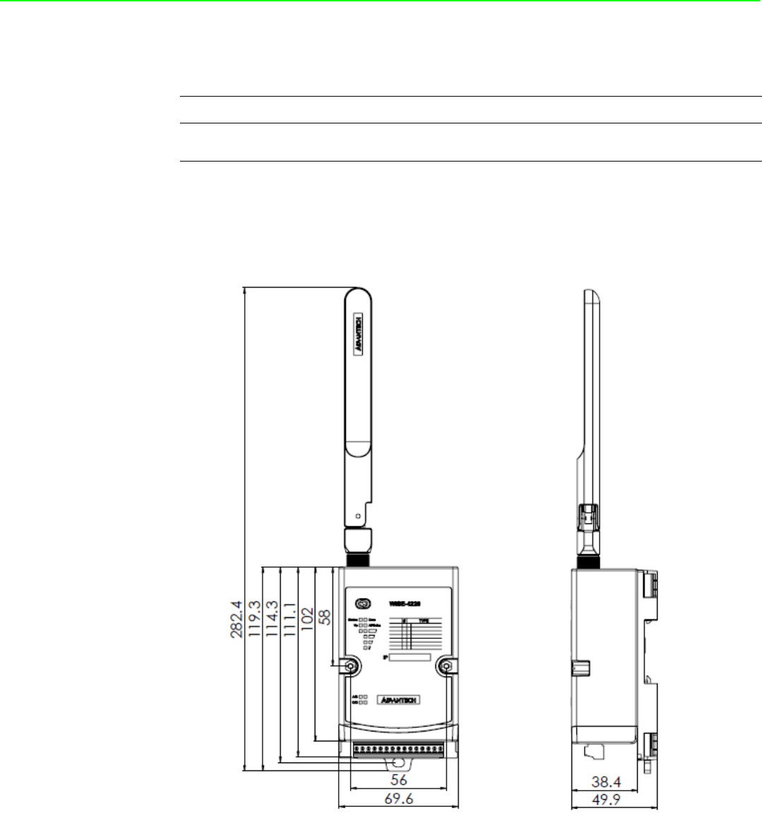
1.2 Mechanical Design and Dimensions
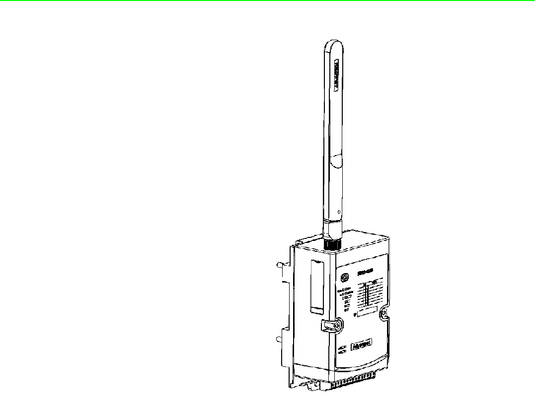
1.2.1 WISE-4220 Series Dimension
Figure 1.1 ME Dimension Front & Side
Function Model Description
Wireless Sensor Node WISE-4220-S231 IoT Wireless Sensor Node with Temperature/
Humidity Sensors
3 WISE-4220 Series User Manual
Chapter 1 Product Overview
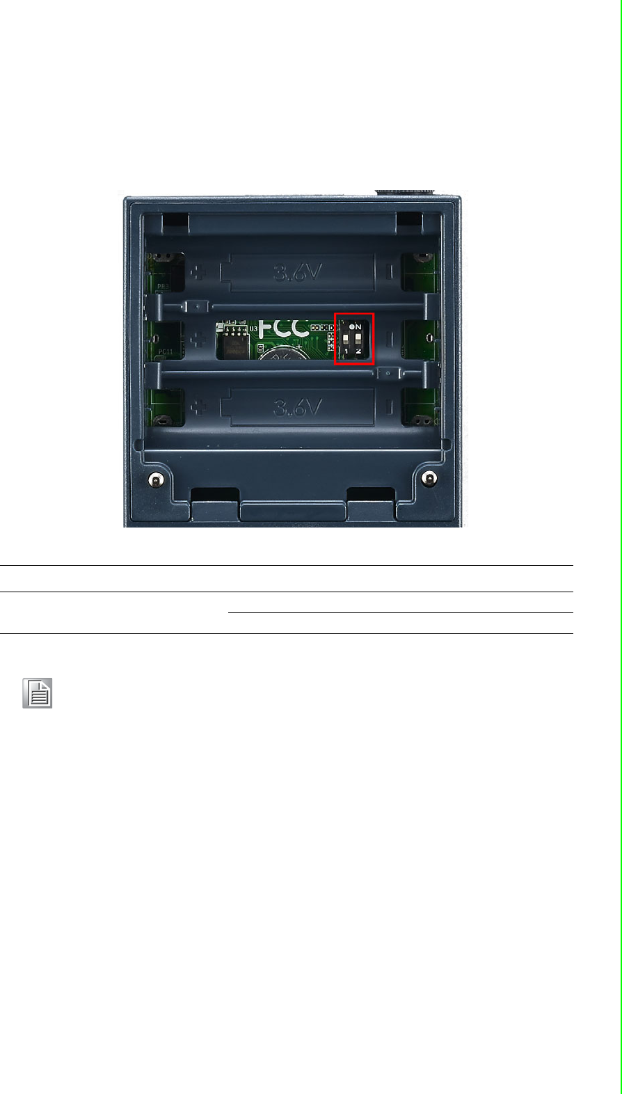
1.3 Switch
Open the housing behide the WISE-4220 module, you can see a switch inside. The
battery socket is no function for WISE-4220 series. It is reserved for WISE-4220
series.
Switch Description Position ON (Default) OFF
SW1 Operation Mode P1 Normal Mode Initial Mode
P2 N/A N/A
Note! After the position 1 of SW1 been changed, users need to power on the
module again to apply the operation mode.
.
WISE-4220 Series User Manual 4
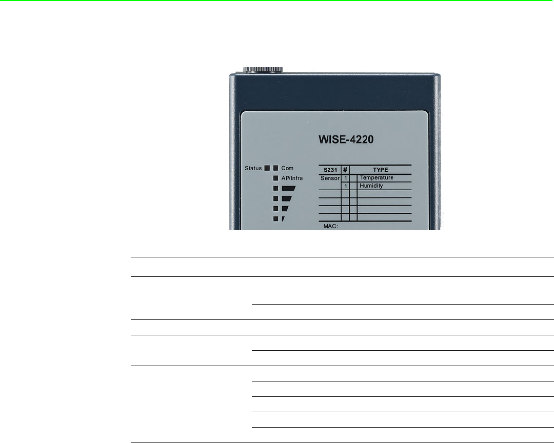
1.4 LED Definition
1.5 Certification and Safety Standard
Electromagnetic Compatibility (EMC)
CE
–EN 55011:2009 +A1:2010 (Group I, Class B)
–EN 55024:2010 +A1:2015
–EN 55032:2015 +AC:2016, Class B
–EN 61000-4-2:2009
–EN 61000-4-3:2006 +A1:2008 +A2:2010
–EN 61000-4-4:2012
–EN 61000-4-5:2014
–EN 61000-4-6:2014
–EN 61000-4-8:2010
–EN 61000-6-1:2017
–EN 61000-6-2:2017
–EN 61000-6-3:2007 +A1:2011 +AC:2012
–EN 61000-6-4:2007 +A1:2011
–EN 301 489-1 V2.1.1 (2017-02)
–EN 301 489-17 V3.1.1 (2017-02)
LED Color Indication Behavior
Status Green Blink 2Hz: Wait for connection
0.5Hz: Network Connected
ON 30 Sec When enable LOCATE function
Com Yellow Blink When TX/RX data in transmission
AP/Infra Green ON Limited AP Mode
OFF Station Mode
Signal
Strength Yellow
ON *4 Full Signal
ON *3 Good Signal
ON *2 Okay Signal
ON *1 Poor Signal
All OFF No Signal / AP Module

5 WISE-4220 Series User Manual
Chapter 1 Product Overview
FCC
–47 CFR FCC Part 15, Subpart B, Class B
–ICES-003:2016 Issue 6, Class B
–ANSI C63.4:2014
CISPR
–CISPR 32:2015 +COR1:2016, Class B
–AS/NZS CISPR 32:2015, Class B
VCCI
–-VCCI-CISPR 32:2016, Class B
Wireless Certification
FCC ID: M82-WISE4220
–47 CFR FCC Part 15, Subpart C (Section 15.247)
–ANSI C63.10:2013
IC: 9404A-WISE-4220
–Canada RSS-247 Issue 2 (2017-02)
–Canada RSS-Gen Issue 4 (2014-11)
–ANSI C63.10:2013
NCC
–LP0002
–ANSIC63.10:2013
TELEC: 001-A08148
RED: Processing
–EN 300 328 V2.2.2 (2016-11)
–EN 63211:2008
RCM:
–AS/NZS 2772.2:2011
–AS/NZS 4268:2017
SRRC: Processing
1.6 Package Information
WISE-4220-S231
WISE-4220 module with bundle antenna and terminal connector x1
Mounting bracket x1
Quick startup manual with China RoHS declare
WISE4220

WISE-4220 Series User Manual 6

Chapter 2
2General Specification

WISE-4220 Series User Manual 8
2.1 General Specification
2.1.1 WLAN Interface
Network Modes
–Infrastructure/Station (Wireless Client)
–Limited AP (Wireless Server)
Standard Conformance
–Infrastructure/Station
802.11b
802.11g
802.11n (2.4GHz only)
–Limited AP
802.11b
802.11g
2.1.2 General
I/O Connector: 3.5mm spacing plug-in screw terminal block
Power Connector: 3.5mm spacing plug-in screw terminal block
Watchdog Timer
–System: 1.6 second
–Communication
–Programmable (FSV)
RTC Accuracy: ±1 min/month
Enclosure: PC
Mounting: DIN 35 rail, wall, and stack
Dimensions (W x H x D): 69 x 38 x 102 mm
Operation Temperature: -25~70°C (-13~158°F)
Storage Temperature: -40~85°C (-40~185°F)
Operating Humidity: 10~ 95% RH (non-condensing)
Storage Humidity: 0~95% RH (non-condensing)
Note! Equipment will operate below 30% humidity. However, static electricity
problems occur much more frequently at lower humidity levels. Make
sure you take adequate precautions when you touch the equipment.
Consider using ground straps, anti-static floor coverings, etc. if you use
the equipment in low humidity environments.
Note! Measuring temperature and humidity will depend on sensor type.
Whether the device is measuring temperature or humidity depends on
the settings of the sensors.

9 WISE-4220 Series User Manual
Chapter 2 General Specification
2.1.3 Power
Power Input Voltage: External Power: 10 ~ 50 VDC
Power Consumption
–WISE-4220-S231: 1.2 W @ 24 VDC
2.1.4 Software
Configuration Interface: Web Interface, Windows Utility
Utility: Adam/Apax .NET Utility
Driver: ADAM .NET Class Library
Industrial Protocol: Modbus/TCP
Supported Protocols: TCP/IP, UDP, HTTP, HTTPS, DHCP, ARP, SNTP
Supports RESTful Web API in JSON format
Supports Web Server in HTML5 with JavaScript & CSS3
2.2 WISE-4220-S231
2.2.1 I/O Specification
2.2.1.1 Temperature Sensor Input
Operating Range: -25°C ~ 70°C (-4°F ~ 157.9°F)
Data Resolution: 0.1 (°C/°F/K)
Accuracy: ±1.0°C (Vertical Installation)
Update Rate: Minimum 1 seconds
Response Time: 15 seconds (Achieving 63% of a step function)
Long Term Drift: 0.05°C/Year (0.09°F/Year)
2.2.1.2 Humidity Sensor Input
Operating Range: 10~90% RH
Resolution: 0.1% RH
Accuracy:
±4% for 0%~50% RH
±6% for 50%~60% RH
±10% for 60%~90% RH
Update Rate: Minimum 1 seconds
Response Time: 10 seconds (Achieving 63% of a step function)
Long Term Drift: 0.5% RH/Year
WISE-4220 Series User Manual 10
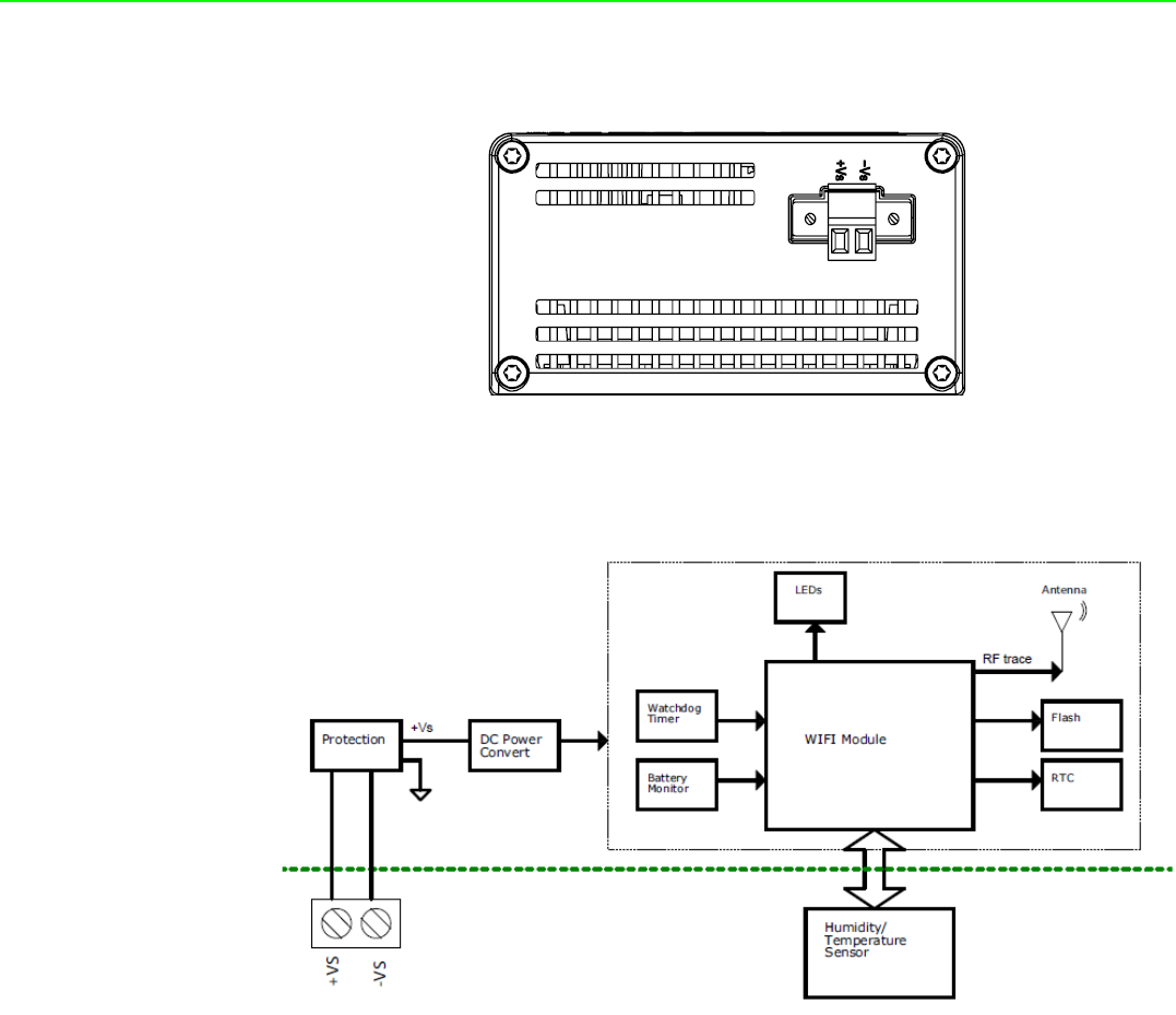
2.2.2 Pin Assignment
Figure 2.1 Pin Assignment
2.2.3 Block Diagram
Figure 2.2 Block Diagram

Chapter 3
3Hardware Installations
WISE-4220 Series User Manual 12
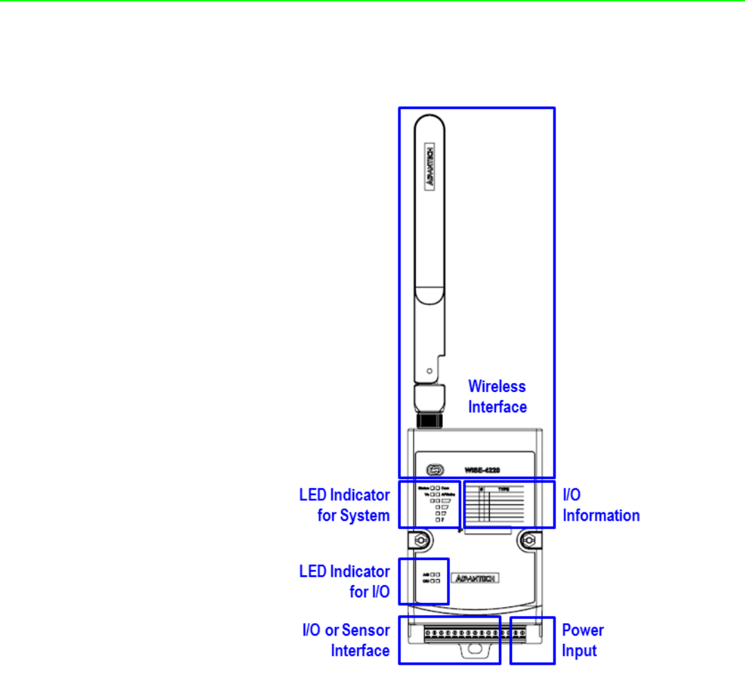
3.1 Interface Introduction
Detailed description of the WISE-4220 interface is shown below.
3.2 Mounting
WISE-4220 modules are designed as compact units and are allowed to be installed
in the field site under the following methods.
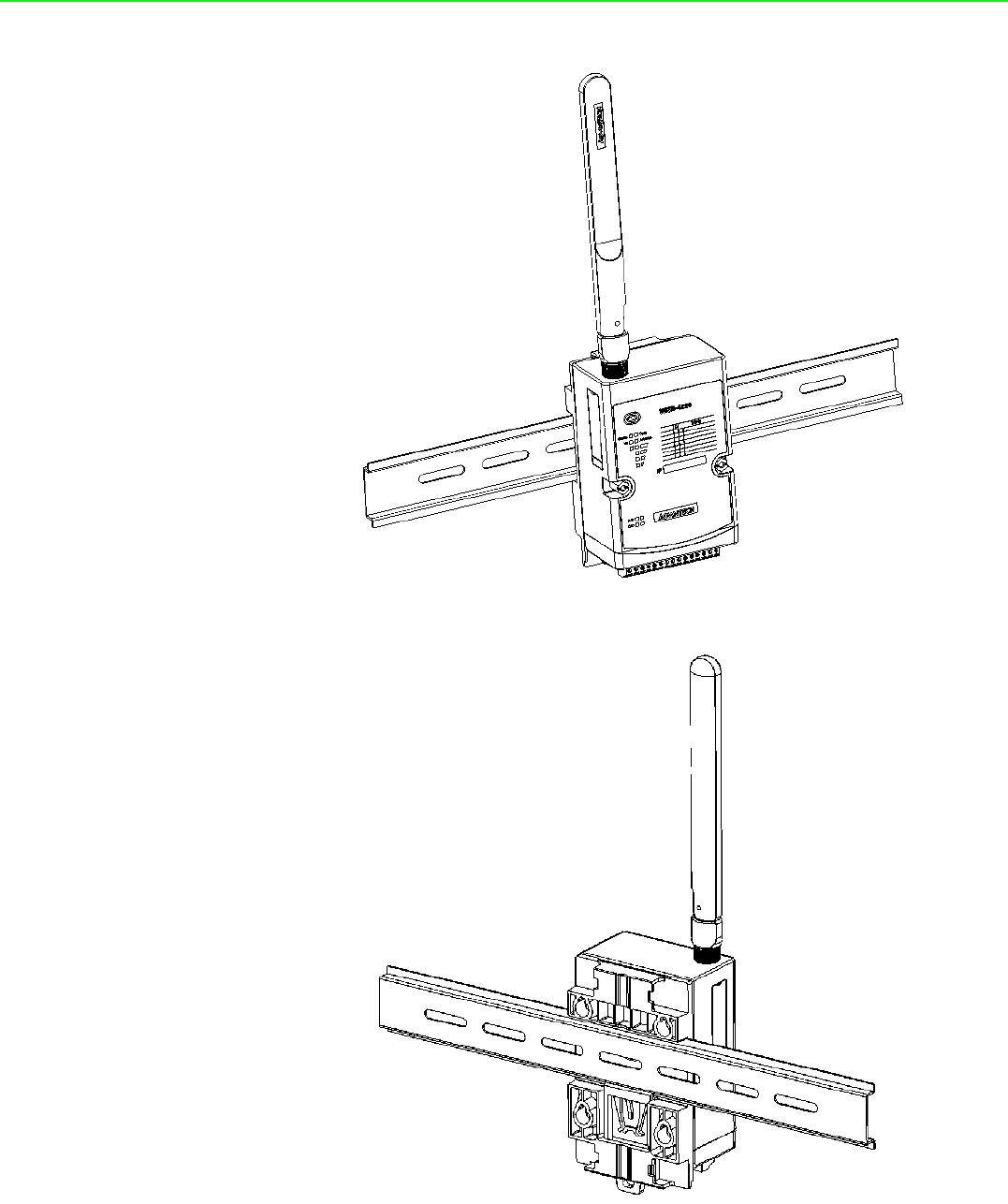
3.2.1 DIN-Rail Mounting
The WISE-4220 module can also be fixed to the cabinet by using mounting rails. You
need to assemble the DIN rail adapter to WISE-4220 module with flathead screw
driver as below. When the module is mounted on a rail, you may also consider using
end brackets at each end of the rail to keep the module from sliding horizontally along
the rail.
13 WISE-4220 Series User Manual
Chapter 3 Hardware Installations
Figure 3.1 DIN Mounting Kit
Figure 3.2 DIN Mounting Install
WISE-4220 Series User Manual 14
Figure 3.3 DIN Mounting Front
Figure 3.4 DIN Mounting Back
15 WISE-4220 Series User Manual
Chapter 3 Hardware Installations
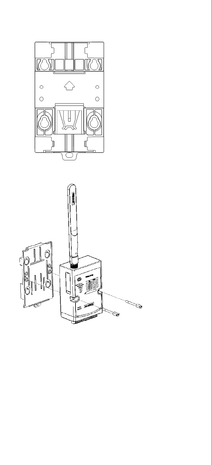
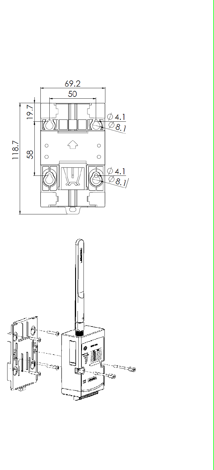
3.2.2 Wall Mounting
Each WISE-4220 module is packed with a plastic wall mounting bracket. Users can
refer to the bracket dimensions and assembly steps to configure an optimal place-
ment in a wall, panel, or cabinet.
Figure 3.5 Wall Mounting Kit Dimension
Figure 3.6 Wall Mounting Install 1
WISE-4220 Series User Manual 16
Figure 3.7 Wall Mounting Install 2
17 WISE-4220 Series User Manual
Chapter 3 Hardware Installations
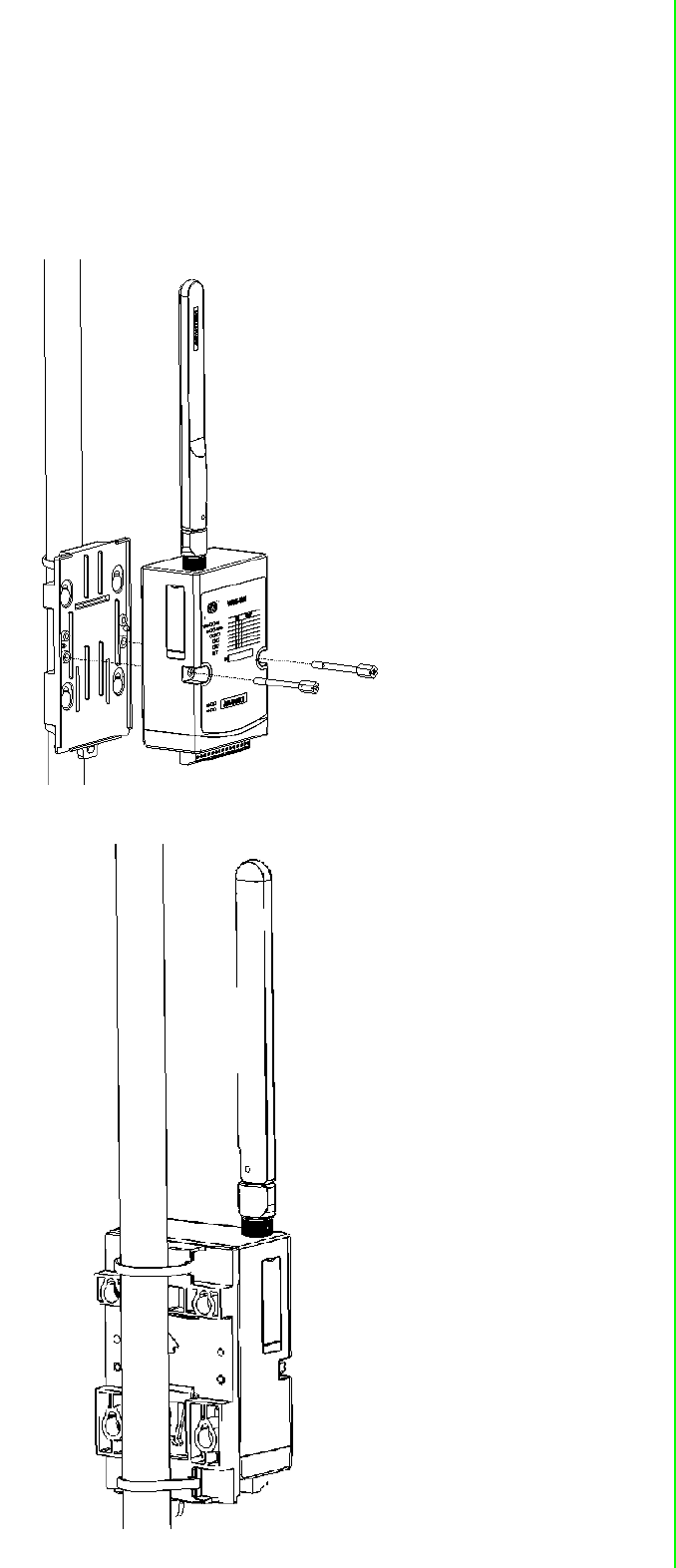
3.2.3 Pole Mounting
Put the pole mounting ring through the middle hole of it. Note that you should unlock the
pole mounting ring with a screw driver before putting it through the device. Then mount
the WISE-4220 module steadily to the pole by locking the pole mounting ring tightly.
Figure 3.8 Polar Mounting Front
Figure 3.9 Polar Mounting Back
WISE-4220 Series User Manual 18
3.3 Wiring & Connections
This section introduces basic information on wiring the power supply and I/O units.
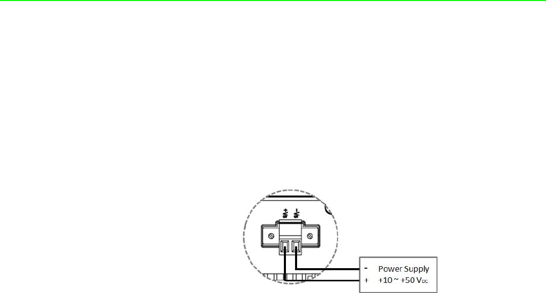
3.3.1 Power Supply Wiring
The system of WISE-4220 is designed for a standard industrial unregulated 24 VDC
power supply. For further application, it can also accept +10 to +50 VDC of power
input, 200mV peak to peak of power ripple, and the immediate ripple voltage should
be maintained between +10 and +50 VDC. Screw terminals +Vs and -Vs are for
power supply wiring.
Figure 3.10 Power Wiring
3.3.2 I/O Units
The system uses a plug-in screw terminal block for the interface between I/O mod-
ules and field devices. The following information must be considered when connect-
ing electrical devices to I/O modules.
The terminal block accepts wires from 0.5 mm to 2.5 mm.
Always use a continuous length of wire. Do not combine wires.
Use the shortest possible wire length.
Use wire trays for routing where possible.
Avoid running wires near high-energy wiring.
Avoid running input wiring in close proximity to output wiring.
Avoid creating sharp bends in the wires.

Chapter 4
4System Configuration
WISE-4220 Series User Manual 20
4.1 Connection
1. Plug a DC power source into the +Vs, -Vs pin of your module to turn on the
power.
2. When users set the switch to “ON” as Section 1.3 shows, the module will be set
to normal mode and the default setting for this operation mode is AP mode. If
you want to set the module to Initial Mode (i.e. factory default mode), you can
change position 1 of SW1 to “OFF”. The module will only work in AP Mode
when the module is in Initial Mode.
4.2 Configure WISE Using Web Interface
4.2.1 System Requirements
The web utility of WISE-4220 module is developed with public HTML 5, but for
detailed indication and data transmission modes, the type of web utility will depend
on web page of the operating system. For mobile devices, the minimum system
requirements of web browsers are as below:
Safari 6 in Apple iOS
Web Browser in Google Android 4.0 (Ice Cream Sandwich)
Chrome in Google Android 4.0 (Ice Cream Sandwich)
For PC platforms, the minimum requirements of web browsers are as below:
Internet Explorer (version 11)
Google Chrome (version 30)
Mozilla Firefox (version 25)
Mobile Browser Chrome Android Safari
Configuration Y Y Y
File Upload N N N
Data Log Chart Y Y Y
Data Log Export N N N
Mobile Browser Chrome Firefox Safari IE11 IE10
Configuration Y Y Y Y Y
File Upload Y Y N Y N
Data Log Chart Y Y Y Y Y
Data Log Export Y Y N N N

21 WISE-4220 Series User Manual
Chapter 4 System Configuration
4.2.2 Factory Default Settings
WISE-4220 Series
Operation Mode: Normal Mode
Wireless Mode: AP Mode
IP Mode: Static IP Address
Default IP: 192.168.1.1
Subnet Mask: 255.255.255.0
Default Gateway: 192.168.1.1
DHCP Server: Enabled
Default Connection Timeout: 720 seconds
HTTP Port: 80
4.2.3 Module Authorization
Account Default Password Access Ability
root 00000000 All privileges
admin 00000000 All privileges except access control configuration
user 00000000 View module status only. Not allow to change configurations
Functions Account
root admin user
Device information View View View
Device setting Edit Edit Deny
System Restart Edit Edit Edit
Module Locate Edit Edit Edit
Change passwords Edit Deny Deny
Reset Password Edit Deny Deny
Reset to default Edit Deny Deny
Access control configurations Edit Edit Deny
Group configurations Edit Edit Deny
Download/upload processes Edit Edit Deny
Network configurations Edit Edit View
I/O configurations Edit Edit View
I/O statuses monitor View View View
Reset AI calibration to default Edit Deny Deny
MODBUS addresses Edit Edit View
Data log configuration and query Edit Edit View
Clear data log Edit Edit Deny
WISE-4220 Series User Manual 22
4.2.4 Operation Mode
The operation mode can be configured by switch SW1 on the back of module. Please
refer to previous chapter for the detail of configuring SW1.
4.2.5 Using Web Browser to Configure the Module
Configure URL: http://IP_address/config
Default URL: http://192.168.1.1/config
Configuration Steps
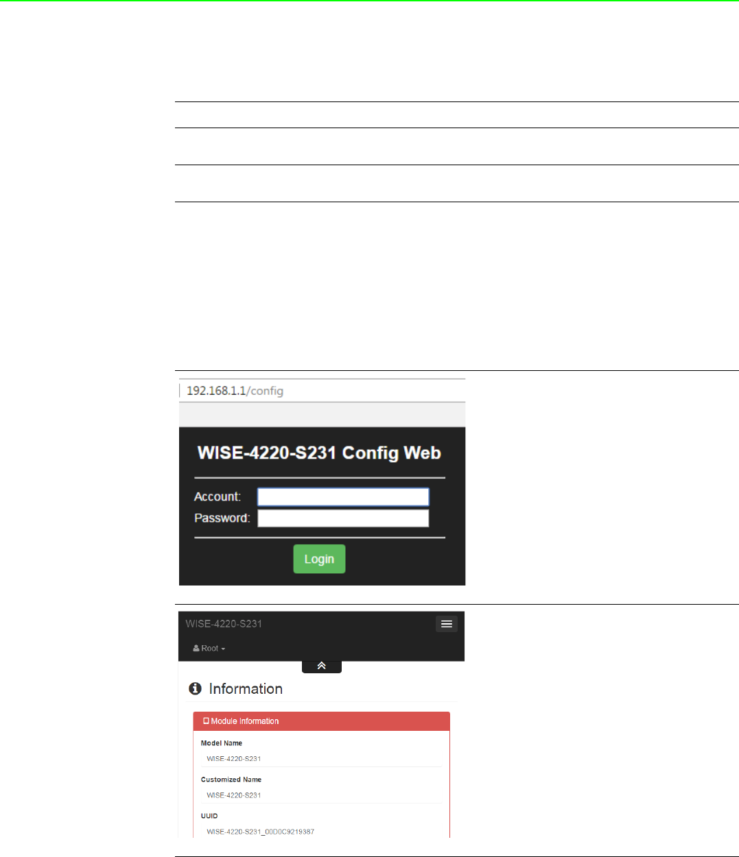
4.2.5.1 Login Web Configuration Page
Mode WISE-4220 Series
Initial Mode Fixed IP address: 192.168.1.1
Fixed Wi-Fi Mode: AP Mode
Normal Mode Default IP address: 192.168.1.1
Default Wi-Fi Mode: AP Mode
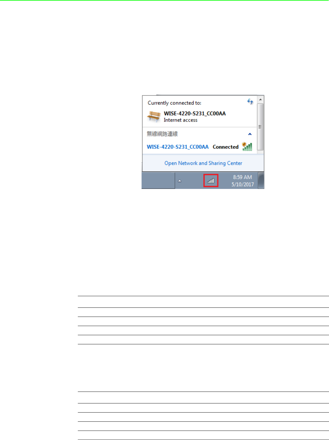
Login
1. Connect your smartphone to your
local Ethernet network and open the
browser of your smartphone.
2. Enter IP address of module with "/con-
fig", for example, the default URL is
http://192.168.1.1/config
3. Enter the account and password. Then
click Login button.
Information
4. After login, you will see the
configuration web page.
23 WISE-4220 Series User Manual
Chapter 4 System Configuration
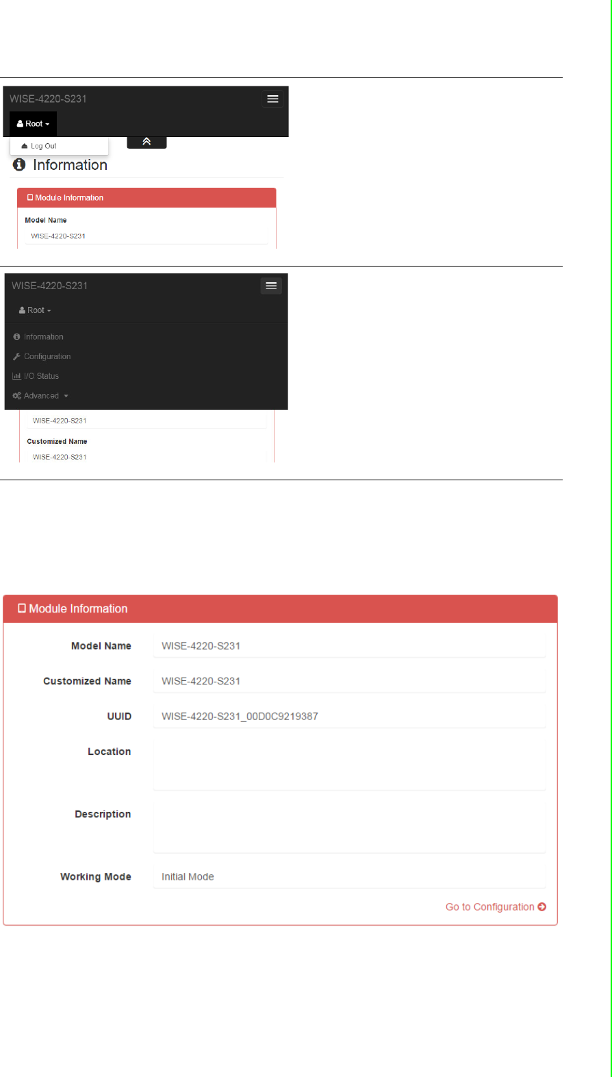
4.2.5.2 System Information
In the information page, you can see the dashboard: module detail, network setting,
and module information, including the firmware version.
Change User
5. Scroll down the tab, and you can
change the login user here.
Menu
6. Click the button on the top, and you
can switch to other pages.
WISE-4220 Series User Manual 24
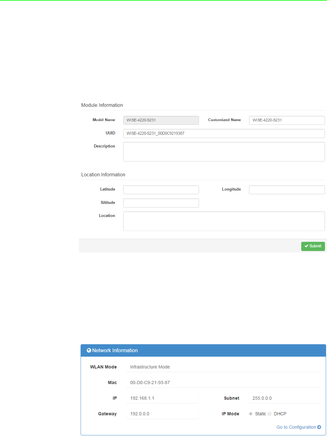
4.2.5.3 Module
You can see the naming of the module and related information. Click “Go to Configu-
ration” to view or change the configurations:
Model Name: Model name of the WISE module
Customized Name / UUID: Refer to Model name and UUID of the module. The
default UUID is the combination of model name and the MAC address. This can
be modified.
Location Information: The location of the module can be stated here.
Description: Any comments about this module can be stated here.
Working Mode: Refer to 4.2.4 for Operation Mode
4.2.5.4 Wireless Status
For WISE-4220 series, users can refer to the WLAN RSSI indicators for the signal
quality in Wireless Status section. It also shows the MAC ID of the client device. If the
module is in AP Mode, the WLAN RSSI Level and Refresh button will not be shown.
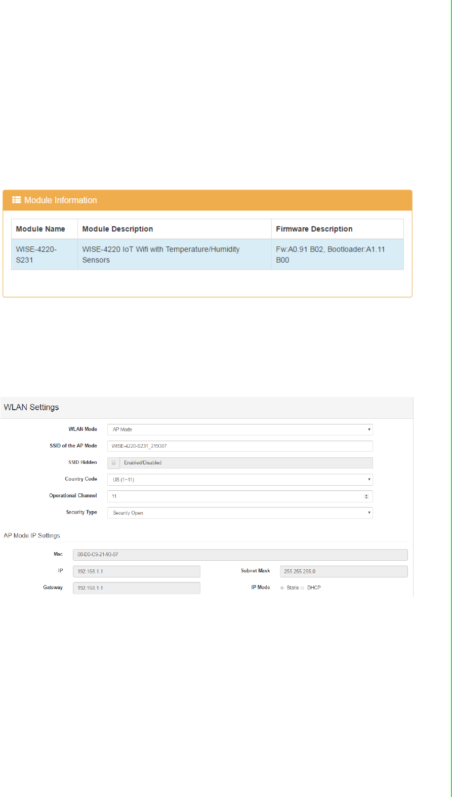
4.2.5.5 Network Information
For WISE-4220 series, WLAN Mode (AP Mode / Infrastructure) will be shown in Net-
work Information section. Here is an overview of the entire network configuration. To
configure the network configuration, click “Go to Configuration.”
25 WISE-4220 Series User Manual
Chapter 4 System Configuration
4.2.5.6 Module Information
Here you can check the model name and the module description. The firmware ver-
sion will also been shown here. At the end of the configuration web page, you can
see the version. For the normal release module, the version on the configuration web
page will increase with the firmware version. These versions have to be updated
simultaneously.
To update the firmware version, go the “Firmware Version” section.
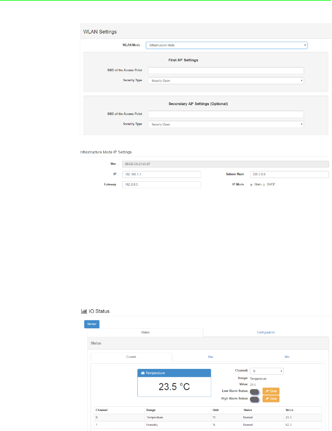
4.2.5.7 Network Configuration
AP Mode
When setting the module to AP mode, users can configure the SSID and also
decide how the WISE module works, including security. The “AP Mode IP Set-
tings” are fixed and do not allow users to make changes.
Infrastructure Mode
When using the module in “Infrastructure Mode”, users need to enter the SSID
of the Access Point (AP) that the WISE module is going to connect, and config-
ure the security type here. WISE-4220 series modules provide a “Second AP
Setting” section, an optional setting for the WISE module to connect to another
AP automatically. If you do not have a second AP, just leave the SSID blank.
After configuring the AP that the WISE module wants to access, the IP address
also needs to be defined in the Infrastructure-Network.
WISE-4220 Series User Manual 26
4.2.5.8 IO Status
The IO family of WISE-4220 series is composed of various types of IO, including tem-
perature and humidity sensors, DI, DO and AI. You can select the models which meet
your requirements based on the applications.
WISE-4220-S231:
–Temperature and Humidity Sensors
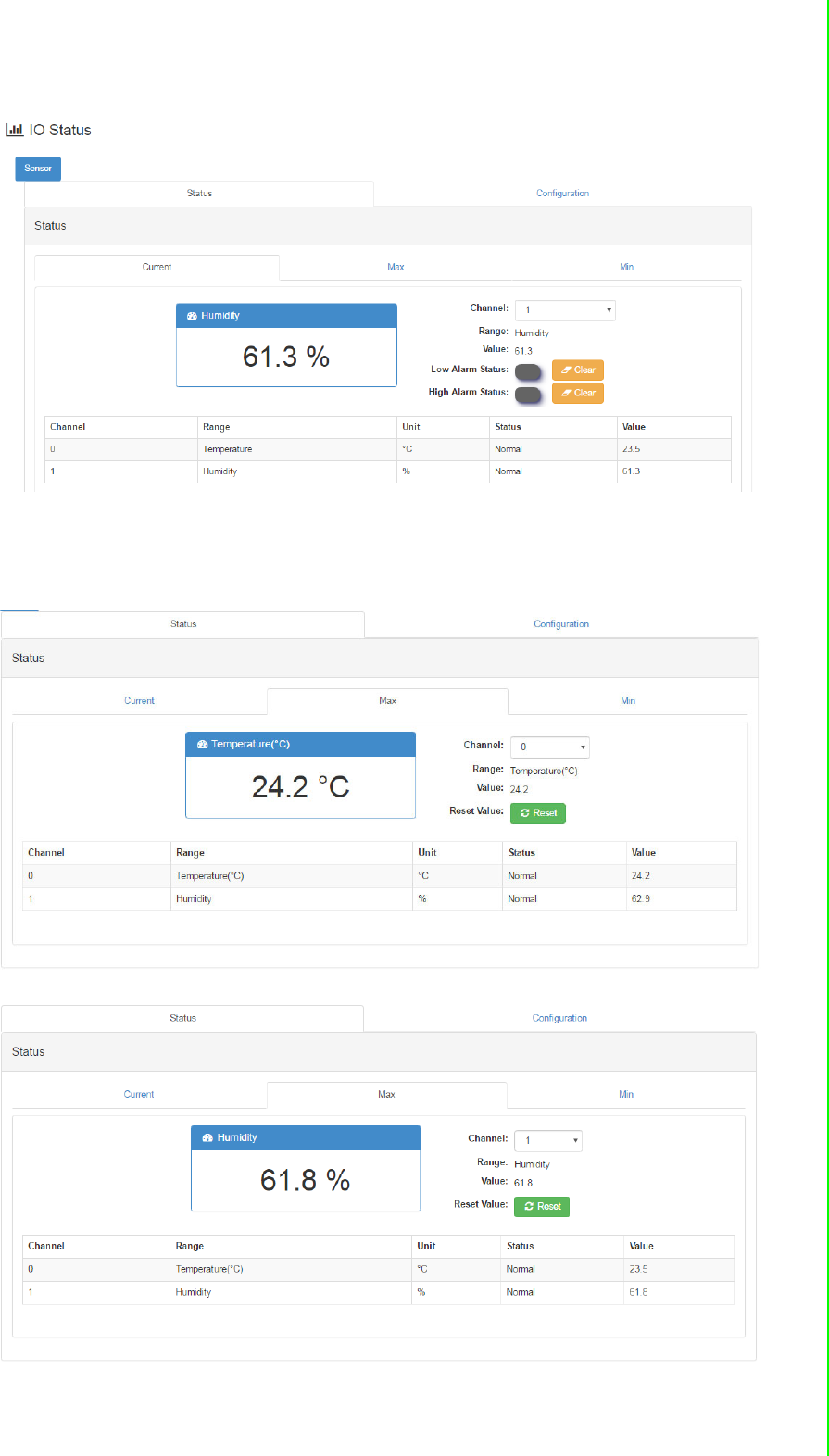
WISE-4220-S231 is equipped with built-in temperature and humidity sensors. As you
can see, the IO status section shows measured results. Channel 0 and 1 present the
measured temperatures and humidity from the sensors, respectively.
27 WISE-4220 Series User Manual
Chapter 4 System Configuration
You can also view the maximal and minimal measured results from the historical
record by selecting “Max” and “Min” tabs. By clicking “Reset,” you can reset the max-
imal and minimal records in the module.
You can also change the settings of channel 0 and 1 in the “configuration” tab. The
fields that can be changed are shown as follows:
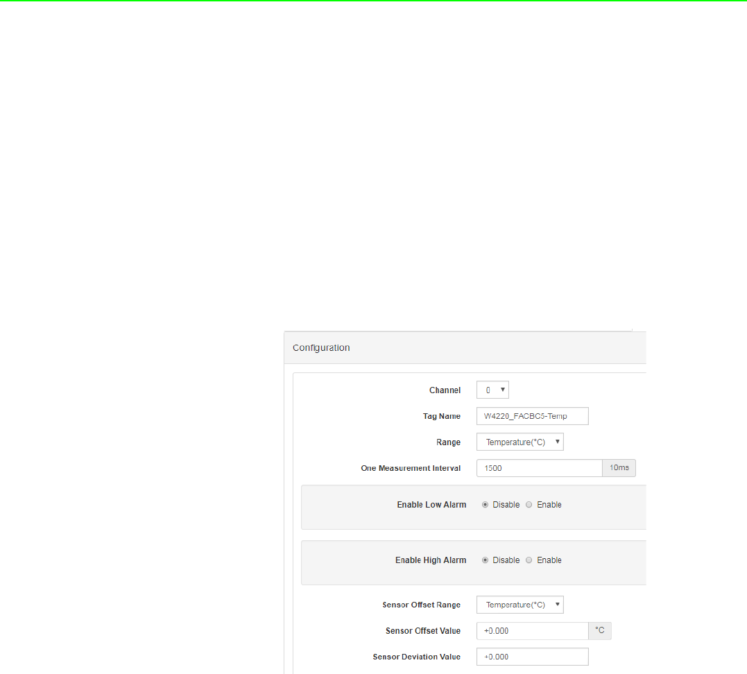
WISE-4220 Series User Manual 28
Tag Name: The name of the node
Range: The unit used by each measured factor
One Measurement Interval: The time interval between two measurement
events
Enable Low Alarm: If you enable this option, the module will send out an alarm
signal when the measured results are below than the lower limit.
Enable High Alarm: If you enable this option, the module will send out alarm
signal when the measured results are higher than the lower limit.
Sensor Deviation Value: The difference of measured results of two consecu-
tive events. If the measured difference is higher than the deviation value you
set, it will trigger an event.
Sensor Offset Range: The unit used to offset the measured number.
Sensor Offset Value: The delta value used to offset the measured number dis-
played in the “Status” section.
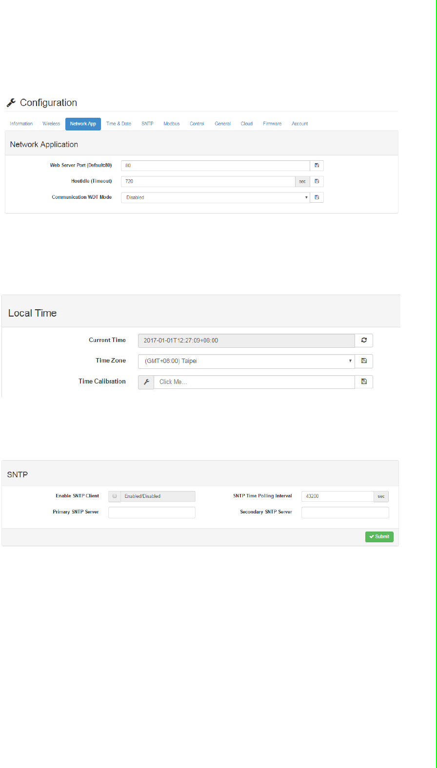
4.2.5.9 System Configuration
Network Application
You can configure the Web Server Port, Host Idle (timeout), and decide whether to
enable Communication WDT or not in the section. The “Web Server Port” field deter-
mines which Ethernet port will be used for the web service, such as the web configu-
ration and RESTful Web API. The default port is 80, but if you change the port
number to 8080, you will have to access the module through http://192.168.1.1:8080/
config in AP mode.
The Host Idle (Timeout) field dictates the availability of the TCP connection between
the host controller and WISE. Each MCU-based WISE module supports four TCP
connections from visitors simultaneously. In this case, if one of the hosts stops com-
municating with the WISE module for a time period longer than the configured host
idle time (for example, the default 720 seconds), the WISE module will terminate the
TCP connection with the host.
The Communication WDT has a Host Idle time, and will be triggered when all TCP
connections are closed. This includes all hosts which visit WISE and the communica-
tion between remote servers like Dropbox or private servers. Once the Communica-
29 WISE-4220 Series User Manual
Chapter 4 System Configuration
tion WDT mode is enabled, it will trigger system events, such as FSV of output
channel and system log.
Time & Date / SNTP
You can see the current time, select the time zone you want to use, and calibrate the
time by clicking “Click Me” to inquire time from host devices.
You can enable SNTP, so that the module can act as an SNTP client to perform time
synchronization from an assigned SNTP server.
WISE-4220 Series User Manual 30
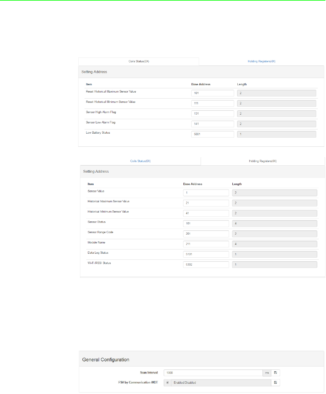
Modbus Address
In order to provide flexibility and scalability for module deployment, we release the
Modbus address setting table, so that you can configure based on your needs. There
are two Modbus address sections (0X and 4X).
General Configuration
“Scan Interval” determines the I/O polling interval in the “I/O Status” section. The
changed values will not be saved into the module. The change is only valid until the
module is powered off. The “FSV by Communication WDT” determines whether to
enable the FSV function triggered by communication with WDT. You can enable the
FSV function for all the output channels of the module here.
31 WISE-4220 Series User Manual
Chapter 4 System Configuration
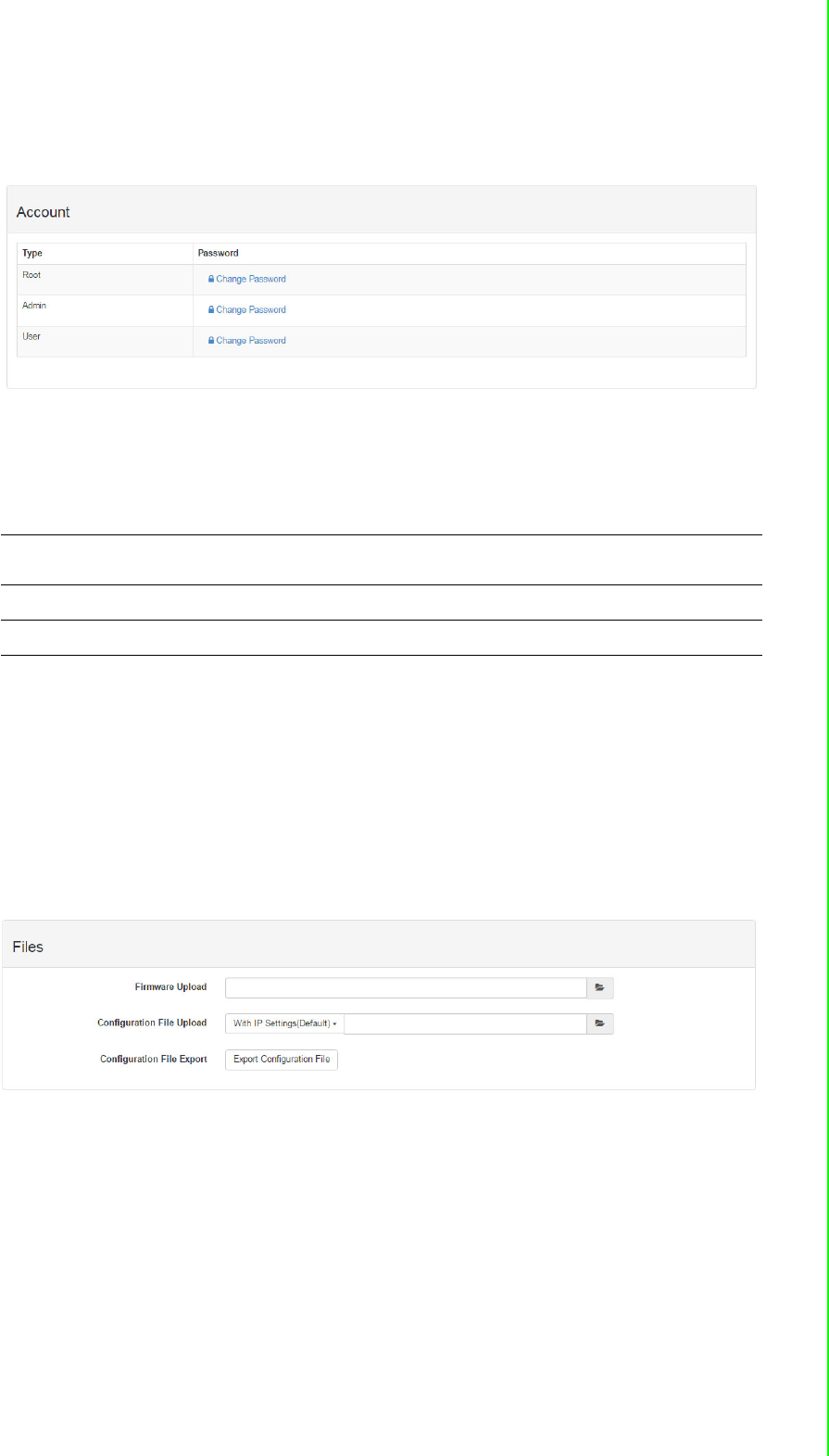
Account Management
Change the password for each account here.
4.2.5.10 System Configuration File
This section demonstrates how to update or download the configuration file from
WISE modules. The following items will be saved in the configuration file:
Download Configuration File from Module
Go to the “Firmware” page in system configuration and click the “Download
Configuration File” button. The configurations will be saved as a file.
Update Configuration File to Module
Go to the “Firmware” page in system configuration and click the icon to select
the configuration file you want to upload from the local folder. Before uploading
the configuration file to the module, select whether or not to apply the IP settings
to the WISE module.
Configuration Information, Wireless, Network App, Time & Data, SNTP, Modbus,
General Cloud, and Account
I/O Status I/O Configuration
Advanced Access Control, Data Logger (Data log and Cloud upload)
WISE-4220 Series User Manual 32
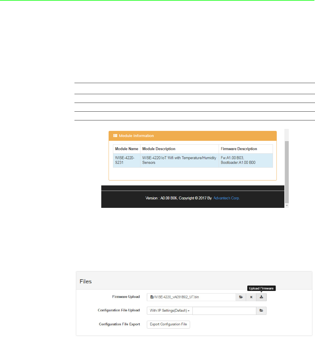
4.2.5.11 Firmware Version
Check Version
The firmware version is shown in the "System Information" page. At the end of the
configuration web page, check the version. For normal release module, the version
on the configuration web page will increase with the firmware version, as these have
to been updated at the same time.
Here is the table list the versions in following figure:
Update Firmware
Go to the “Firmware” page in system configuration and click the icon to select the
configuration file you want to upload from the local folder. You can find the latest offi-
cial release firmware file at the Advantech support site (http://support.advan-
tech.com/support/).
Type Version
Firmware A1.00 B03
Bootloader A1.00 B00
Web Page A0.00 B06
33 WISE-4220 Series User Manual
Chapter 4 System Configuration
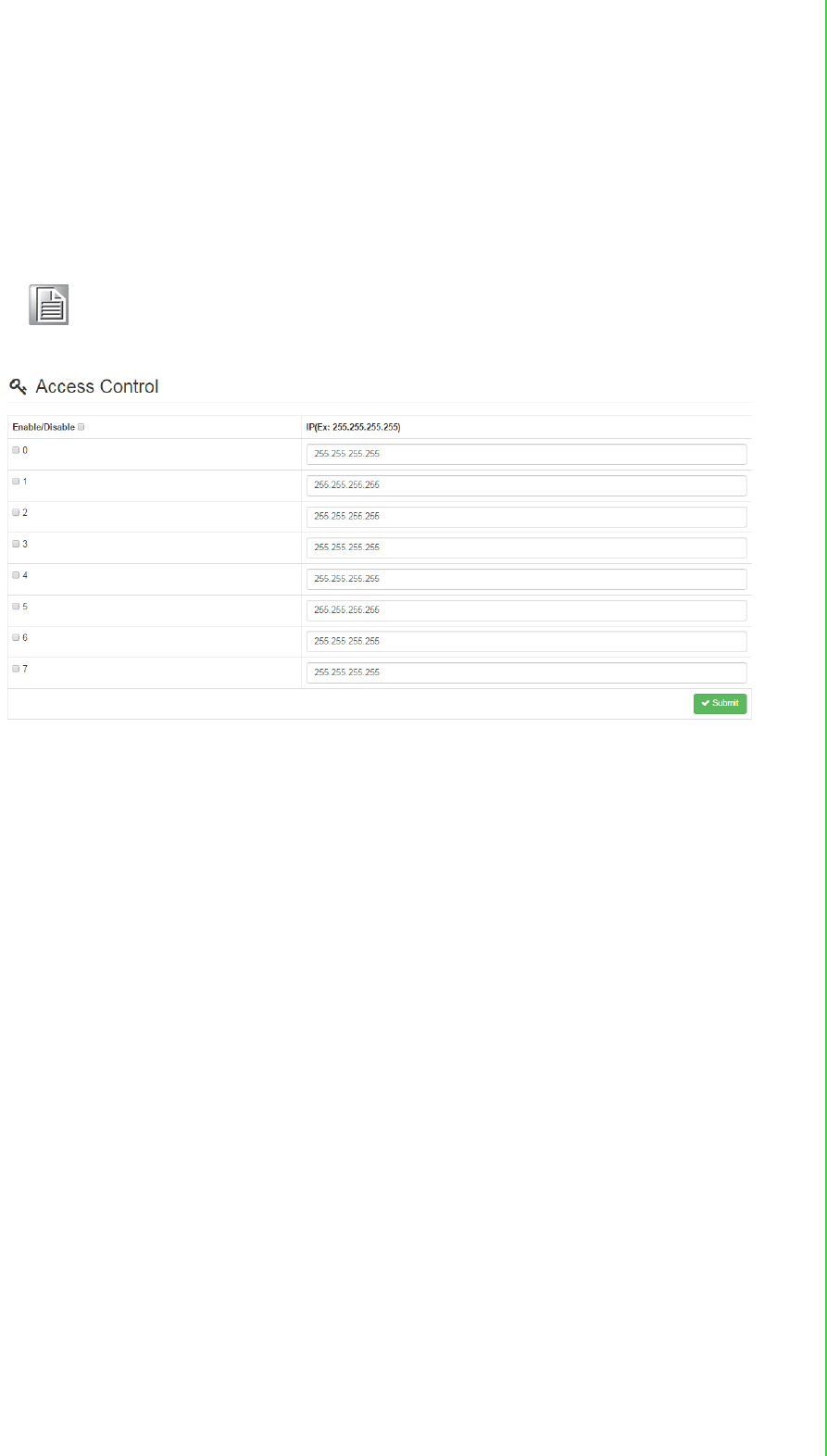
4.2.5.12 Access Control for Security
To avoid unauthorized access, you can manage the list of devices that can access
the WISE-4220 module by using the “Access Control” section. Please enable one of
the rows and enter the IP address or MAC address of the devices that are allowed to
access the WISE-4220 module.
4.2.5.13 Data Logger
The WISE-4220 series supports data log functions. I/O status can be logged in the
module and queried from the module.
Time & Date / SNTP
Before you start the log function, please make sure that the RTC time inside the
WISE module is correct. Standard WISE modules, excluding WISE-4012E, come
with an RTC battery. Once the RTC time has been configured, you don't need to syn-
chronize the time with SNTP server. The time will be kept in the RTC with a battery.
For the WISE-4012E without an RTC battery, you need to synchronize the time with
SNTP server.
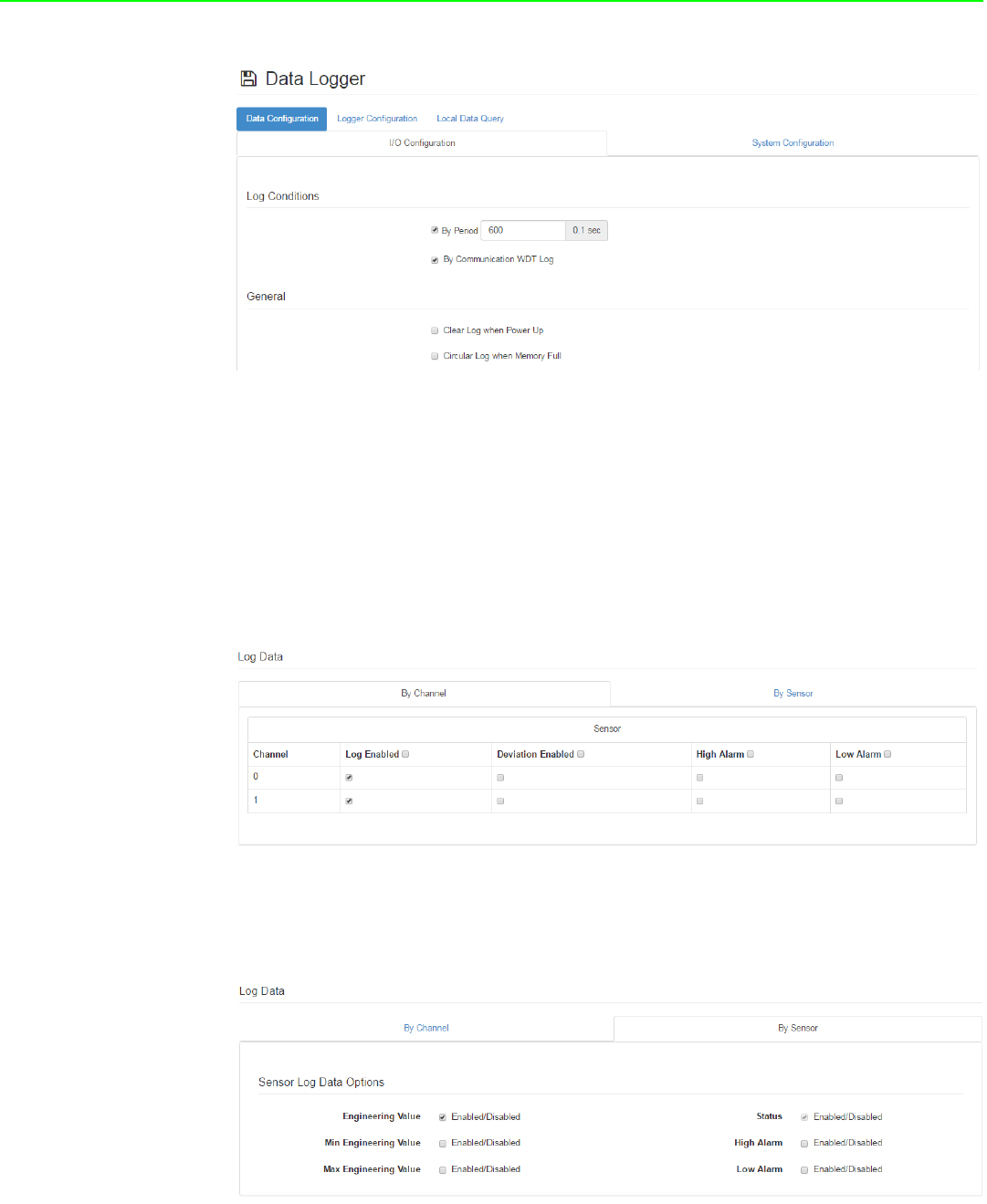
Data Configuration
–I/O Data
You can use the “Log Conditions” section in “Data Configuration” to choose the
method that will be used to log data. If you check “By Period” box, it will enable peri-
odic logging, and the log period can be assigned in the following field. Note that the
unit of this field is 0.1 second, meaning that the status of I/O will be logged every min-
ute if you enter “600” here. If you check the box “By Communication WDT”, once the
condition of the WDT is met, the status of the I/O will be logged.
For the analog input channel, data can be logged by the AI Deviation Rate (Dividing
difference between present sample value and previous sample value by the total
range value). Here you can enter the percentage of the deviation rate to be the crite-
ria for triggering the logger.
All the data can be kept even if the module is powered off; however, you can clear all
data in the logger when powering up WISE module by checking the “Clear Log when
Power Up” box. When maximum memory capacity is achieved, the logger will stop
logging by default. You can check the “Circular Log when Memory Full” box to over-
write the memory.
Note! For WISE-4220 wireless modules, users can only configure access con-
trol by the IP address, not the MAC address.
WISE-4220 Series User Manual 34
The “By Channel” tab is used to determine which kind of status will be logged and
whether the change of the status will be logged or not. Note that the log memory will
be cleared if any parameter is changed in the “By Channel” and “By Sensor.”
For S231 sensor channel, check the “Log Enabled” box to log the status of checked
channel periodically. After you check "Log Enabled" box, you can check the
"Deviation Enabled" box if you want to log data when the deviation matches the crite-
ria set in "Sensor Deviation Value" field of the "IO Status" section. You can also
choose to log the events that trigger high and low alarms by checking “High Alarm”
and “Low Alarm” boxes.
The “By Sensor” tab is used to decide what kinds of data will be logged. Note that the
log memory will be cleared once any parameter changed in the “By Channel” and “By
Sensor” tabs.
35 WISE-4220 Series User Manual
Chapter 4 System Configuration
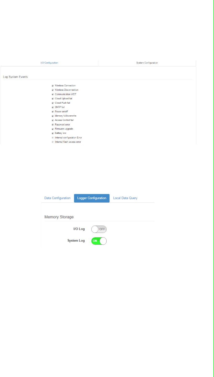
4.2.5.14 System Data
The WISE data logger function not only logs the I/O status, but also logs system
events for module diagnostics or troubleshooting. You can choose what kind of sys-
tem events you would like to log here.
Logger Configuration
In the previous page, you can configure which data is logged. In this page you can
enable the local memory storage function. There are separate switches to enable the
function of logging I/O data and system data. You can turn ON the switches to enable
the function.
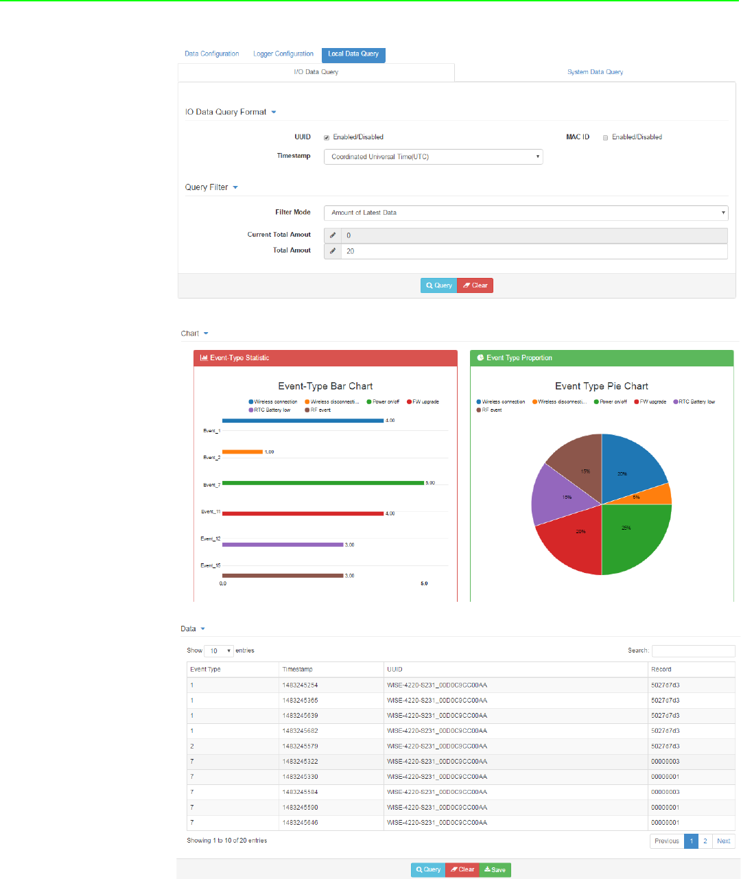
Local Data Query
The logged data can be queried from the WISE module. Due to the limitation of MCU-
based WISE modules, the file will be saved in a *.json file. You can visit https://json-
csv.com/ to convert the data from *.json to *.csv.
Before querying the logged data, you can configure the format of the file. You can
determine whether the data comes with a UUID or MAC ID, and choose the type of
time stamp. For the latest version of WISE module, which supports Local Date and
Time (GMT), the time stamp will be reported in the format like this: "2015-08-
27T15:20:29+08:00", whereas the time stamp will look like: “1440660089,” if it sup-
ports Coordinated Universal Time (UTC).
After selecting the data format, you can query the amount of data or data within a cer-
tain period by selecting “Amount of Latest Data” or “Time Filter” modes, respectively.
However, if the amount of data is not too large, you can also choose “No Filter
Enabled” to query all the data.
Now you can click Query to query the data from local memory. Then the data will be
shown in a chart and table. Click “Save” to save data from the WISE module into a
*.json file, or you can click “Clear” to clear all data in local memory.
WISE-4220 Series User Manual 36
37 WISE-4220 Series User Manual
Chapter 4 System Configuration
4.2.5.15 Cloud Logger
Dropbox
Refer to section 4.2.6 Configuring Cloud Server for Dropbox cloud logger.
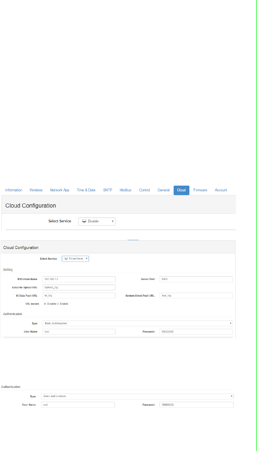
Private Server
If you don't want to push the data to a public file-based cloud like Dropbox, WISE
also supports a “Private Server” function which pushes data to a private web server
directly. You can setup your own web service to retrieve data from the WISE module,
or use the example agent on your own server to retrieve the files pushed from the
WISE module.
Go to “Cloud Configuration” page and select “Private Server.” Then configure the Pri-
vate Server Setting. If you would like to use the example agent provided by WISE,
you need to confirm the Server IP and Server Port, and make sure the server port
you configure is not occupied by another application on your private server. To setup
your own application to retrieve files from WISE, you need to configure the URL. We
also support SSL security with Dropbox, in order to provide you a safe private cloud
solution. Once SSL security is enabled, you need to setup the SSL service on your
private server.
If you are not able to setup the SSL service, there is another option for internet secu-
rity. You can use “Authentication” section for the private server with a User Name and
Password provided by our example agent.
After “Cloud Configuration” is configured as a private server, you can go back to the
Logger Configuration page in Data Logger. Before switching Cloud Upload to ON,
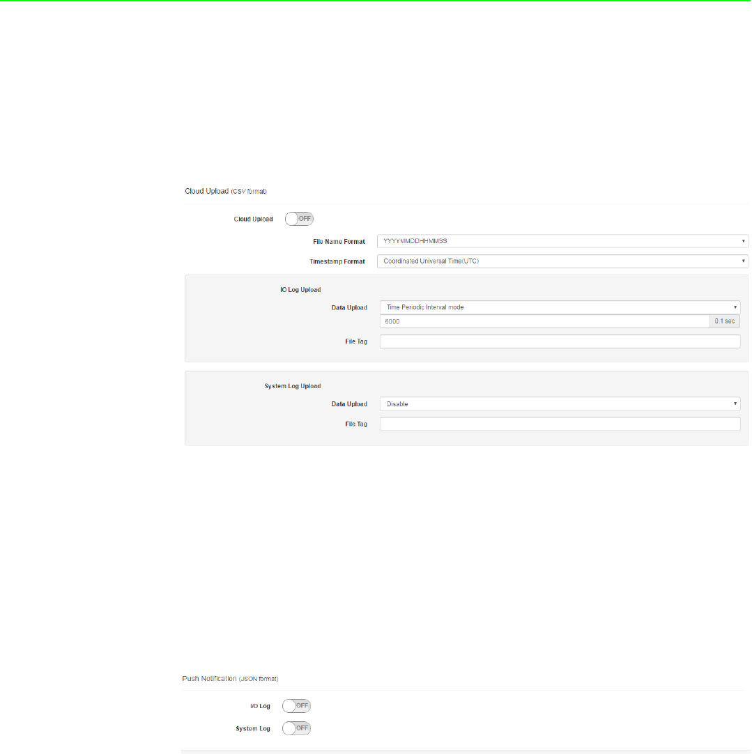
WISE-4220 Series User Manual 38
you can configure the data upload criteria for I/O signal and system diagnosis individ-
ually.
You can choose to push a certain amount of data by using Item Periodic Interval
mode, or push data within a certain period of time (Unit: 0.1 sec) by using Time Peri-
odic Interval mode. If you don't want to upload I/O or system data, choose “Disable”.
After configuring the upload criteria, you can switch Cloud Upload ON and start
uploading. The data will be pushed to the cloud in the format of *.csv.
Push Notification
For Cloud Logger functions including Dropbox Cloud Logger and other private serv-
ers, data comes from the local memory of WISE. You can pack data from the WISE
data logger into a file, and then push it to the web server. Then you can push the lat-
est data when the log condition is triggered with the events such as changes of DI
status.
The WISE module will push a notification in JSON format to the private server. You
can switch the I/O Log or System Log ON, and then the WISE module will start push-
ing the latest logged data to the private server.
39 WISE-4220 Series User Manual
Chapter 4 System Configuration
4.2.6 Configuring Cloud Server
1. Make sure the WISE-4220 module is able to access the Internet, and the device
that’s going to configure the WISE-4220 module is in the same IP domain as the
WISE-4220 module
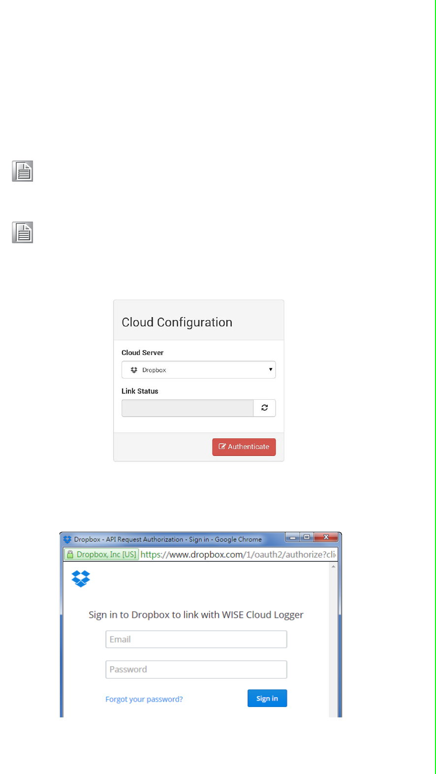
2. Go to the Cloud tab of Configuration.
3. Select Dropbox as the cloud server.
4. The browser will open a new window for Dropbox. Enter your Dropbox account
information including E-mail and Password, then click “Sign in.”
Note! The following instructions use Dropbox. Make sure Dropbox provide
their service in your region or find an alternative public cloud service.
Note! Before start to configure cloud sever, please make sure WISE module is
working in "Infrastructure Mode", and the connected AP is able to
access internet
WISE-4220 Series User Manual 40
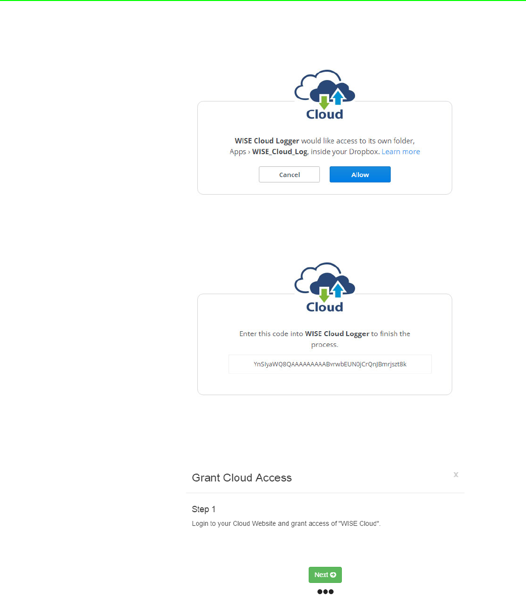
5. After logging in, click "Allow" to allow WISE Cloud Logger Apps to access your
Dropbox account to store the data log file.
6. Dropbox will then provide a code. Copy this code and return to the configuration
web page of the WISE module.
7. Click "Next" to enter the code.
8. Paste the code provided by WISE Cloud Logger, then click "Submit."

41 WISE-4220 Series User Manual
Chapter 4 System Configuration
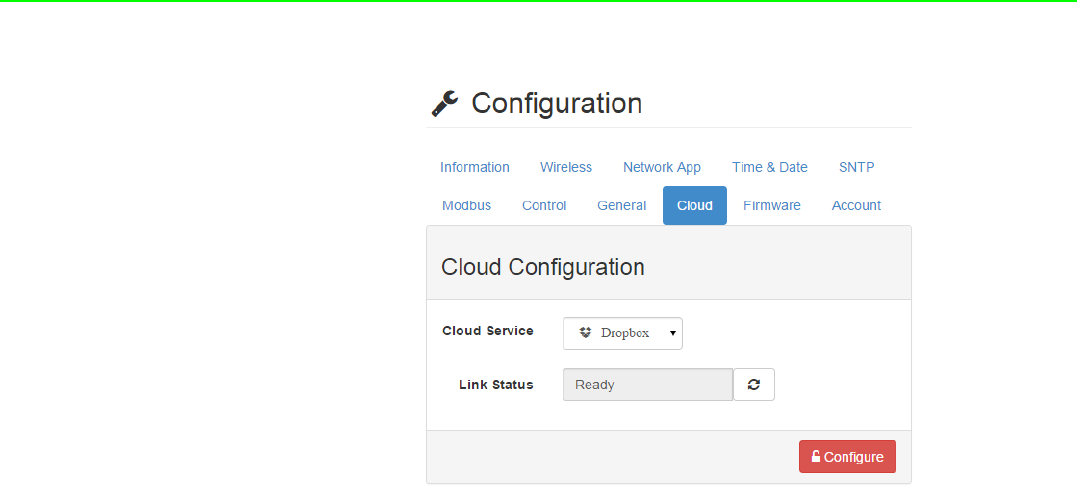
9. If your WISE-4220 module is correctly connected to the Internet, you will be able
to set the functions successfully. Click "Close" to return to Configuration.
10. You will then see the “Link Status” shows “Ready.”
WISE-4220 Series User Manual 42

Appendix A
AModbus Mapping
Table

WISE-4220 Series User Manual 44
A.1 Modbus Function Code Introduction
A.2 WISE-4220-S231 Modbus Mapping Table
Code (Hex) Name Usage
01 Read Coil Status Read Discrete Output Bit
02 Read Input Status Read Discrete Input Bit
03 Read Holding Registers Read 16-bit register. Used to read integer or
floating point process data.
04 Read Input Registers
05 Force Single Coil Write data to force coil ON/OFF
06 Preset Single Register Write data in 16-bit integer format
08 Loopback Diagnosis Diagnostic testing of the communication port
0F Force Multiple Coils Write multiple data to force coil ON/OFF
10 Preset Multiple Registers Write multiple data in 16-bit integer format
Address (0X) Channel Description Attribute
00101 Temperature Reset Historical Max. Sensor
Value
Write
00102 Humidity Write
00111 Temperature Reset Historical Min. Sensor
Value
Write
00112 Humidity Write
00131 Temperature High Alarm Flag Read
00132 Humidity Read
00141 Temperature Low Alarm Flag Read
00142 Humidity Read
05001 RTC Battery Low Read
Address (4X) Channel Description Attribute
40001 Temperature Sensor Value Read
40002 Humidity Read
40101~40102 Temperature Sensor Status* Read
40103~40104 Humidity Read
40021 Temperature Historical Max. Sensor Value Read
40022 Humidity Read
40041 Temperature Historical Min. Sensor Value Read
40042 Humidity Read
40201 Temperature Type Code** Read
40202 Humidity Read

45 WISE-4220 Series User Manual
Appendix A Modbus Mapping Table
* Sensor Status:
** Type Code
*** Data Logger Status
40211 Module Name 1 Read
40212 Module Name 2 Read
45101 Data Logger Status*** Read
Bit Order Description
0 Fail to provide sensor value (sensor not ready)
1~31 Reserved
Type Code Sensor type Sensor type and unit
4096 (0x1000)
Temperature
Temperature (°C)
4097 (0x1001) Temperature (°F)
4098 (0x1002) Temperature (K)
4128 (0x1020) Humidity Humidity (%)
Bit Order Description
0 Built-in logging is out of memory for IO log. (No space left)
1 Built-in memory errors.
2 Built-in logging is out of memory for System log. (No space left)
3 Cloud upload fail
4 Cloud push fail
5-15 Reserved

WISE-4220 Series User Manual 46

Appendix B
BREST for WISE-4220
Series

WISE-4220 Series User Manual 48
B.1 Introduction
Representational State Transfer (REST) is a software architecture for how web appli-
cations and services interact encompassing every thing or entity that can be identi-
fied, named, addressed or handled, in any way whatsoever, on the Web. It can be
developed with compatible popular protocols or standards like HTTP, URI, JSON,
HTML. With the advantage of scalability, simplicity and performance, it's already
adopted by Amazon and Yahoo web services. The web service is developed based
on HTML5 language, if a user need to integrate this into other web services, the fol-
lowing information/command list can be referenced.
B.2 REST Resources for WISE-4220 Series
B.2.1 Sensor Input
/sensor_value/slot_0/ch_num
Description Retrieves information about the sensor input value resource on
specific slot.
URL Structure
http://10.0.0.1/sensor_value/slot_0
http://10.0.0.1/sensor_value/slot_0/ch_num
where num = 0 ~ : the channel number
HTTP Method
GET: Returns the representation of all of analog input value
resource.
PUT: None
PATCH: Apply partial modifications to analog input value resource.
GET
Multi Channel Request:
GET /sensor_value/slot_0
Single Channel Request:
GET /sensor_value/slot_0/ch_num
[Example]
Request: GET /sensor_value/slot_0
Content-type: application/json
Response: 200 OK
{
"SVal": [
{
"Ch":0,
"Rng":4096,
"EgF":0.650,
"HEgF":1.250,
"LEgF":0.500,
"Evt":0,
“LoA”: 0,
“HiA”: 0
"ClrH": 0,
"ClrL": 0,
},
{
"Ch":1,
"Rng":4128,
"EgF":0.000,
"HEgF":0.000,
"LEgF":0.000,
"Evt":0,

49 WISE-4220 Series User Manual
Appendix B REST for WISE-4220 Series
“LoA”: 0,
“HiA”: 0
"ClrH": 0,
"ClrL": 0
}
]
}
Request: GET /sensor_value/slot_0/ch_1
Content-type: application/json
Response: 200 OK
{
"Ch":1,
"Rng":4128,
"Evt":0,
"EgF":0.000,
"HEgF":0.000,
"LEgF":0.000,
“LoA”: 0,
“HiA”: 0
"ClrH": 0,
"ClrL": 0
}
PUT None
PATCH
Single/Multi Channel Request:
PATCH /sensor_value/slot_0
Single Channel Request:
PATCH /sensor_value/slot_0/ch_num
[Example]
Request: PATCH /sensor_value/slot_0
Content-type: application/json
{
" SVal": [
{
"Ch":0,
"ClrH": 0
},
{
"Ch":1,
"ClrL":0
}
]
}
Response: 200 OK
Request: PATCH /sensor_value/slot_0/ch_1
Content-type: application/json
{
"ClrL":0
}
Response: 200 OK

WISE-4220 Series User Manual 50
JSON array name definition:
Resource value definitions (Total channels = AI channel number):
Field Abbreviation Data Type
Array of Sensor value SVal Array
Field Abbreviation Data Type Property Description
Channel
Number Ch Number R 0, 1, …: Sensor input channel number.
Input Range Rng Number R Sensor input range.
Refer to Sensor type code table*
Channel
Event
Status
Evt Number R
Sensor status
Bit Order Description
0Fail to provide Sensor
value (UART timeout)
1~31 Reserved
Clear
Maximum
Sensor Value
ClrH Number W 1 : Clear the Maximum Sensor value
Clear
Minimum
Sensor Value
ClrL Number W 1 : Clear the Minimum Sensor value
Channel
Engineering
data
(floating type)
EgF Number R
Sensor engineering data, the value is
floating type. Unit: According sensor
type code
For example,
999.120 → 999.12 °C
-3.220 → -3.22 °C
Maximum
Sensor
Engineering
data
(floating type)
HEgF Number R
Sensor max. engineering data, the
value is floating type. Unit: According
sensor type code
For example,
10.200 → 10.2 °C
-5.120 → -5.12 °C
Minimum
Sensor
Engineering
data
(floating type)
LEgF Number R
Sensor min. engineering data, the
value is floating type. Unit: According
sensor type code
For example,
250.350 → 250.35 °C
-0.120 → -0.12 °C
Low Alarm
Status LoA Number RW
Low alarm status
Read 1 : low alarm occurred.
0 : not occurred
Write 0 : clear the low alarm status
High Alarm
Status HiA Number RW
High alarm status
Read 1 : high alarm occurred.
0 : not occurred
Write 0 : clear the high alarm status

51 WISE-4220 Series User Manual
Appendix B REST for WISE-4220 Series
* Sensor type code table
Type Code Sensor type Sensor type and unit
4096 (0x1000)
Temperature
Temperature (°C)
4097 (0x1001) Temperature (°F)
4098 (0x1002) Temperature (K)
4128 (0x1020) Humidity Humidity (%)

www.advantech.com
Please verify specifications before quoting. This guide is intended for reference
purposes only.
All product specifications are subject to change without notice.
No part of this publication may be reproduced in any form or by any means,
electronic, photocopying, recording or otherwise, without prior written permis-
sion of the publisher.
All brand and product names are trademarks or registered trademarks of their
respective companies.
© Advantech Co., Ltd. 2017