Aeon Labs FT111 In-Wall Dimmer, Nano Dimmer User Manual 15 FT111 A UserMan
Aeon Labs LLC. In-Wall Dimmer, Nano Dimmer 15 FT111 A UserMan
UserManual.wiki
>
Aeon Labs
>
FT111 User Manual
15_FT111-A UserMan
Navigation menu
Upload a User Manual
Namespaces
Wiki Guide
HTML
PDF
Info
Views
User Manual
Discussion / Help
Navigation

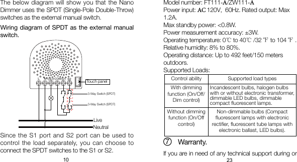
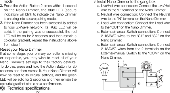
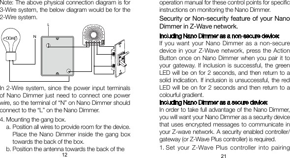
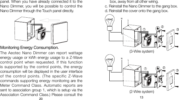
![14 19Note:The gang box should be sized 3×2×2.75 inch/ 75×50×70 mm or larger, minimum volume 14 in / 230cm .Use exible copper conductors only.If a Bypass installation is needed, the Bypass should be in parallel with the bulb load, see below:1).2).3).3 3Warning: The main circuit breaker or fuse must be shut off during the Bypass installation or bulb change.BypassYou can also set the external switch mode through Conguration Command Class. Parameter 120 [1 byte dec] is the parameter that will set one of the 3 different modes. If you set this conguration to:(0) Enter automatic identication mode(1) Momentary push button mode (2) 3-way switch mode (3) 2-state switch modeTouch panel control.As you can see that the Nano Dimmer’s surface has a pin port, this port is used to connect the Touch The Nano Dimmer can be controlled via 2-state (ip/op) external/manual switch, momentary push button or the 3-way switch. To automatically detect and set the mode to the appropriate type of manual switch wired into Nano Dimmer, toggle the button on the manual switch once and wait 2 seconds for the Nano Dimmer to detect the type of manual switch.Restore Power.Restore power at the main circuit breaker or fuse.5.](https://usermanual.wiki/Aeon-Labs/FT111/User-Guide-3245742-Page-15.png)