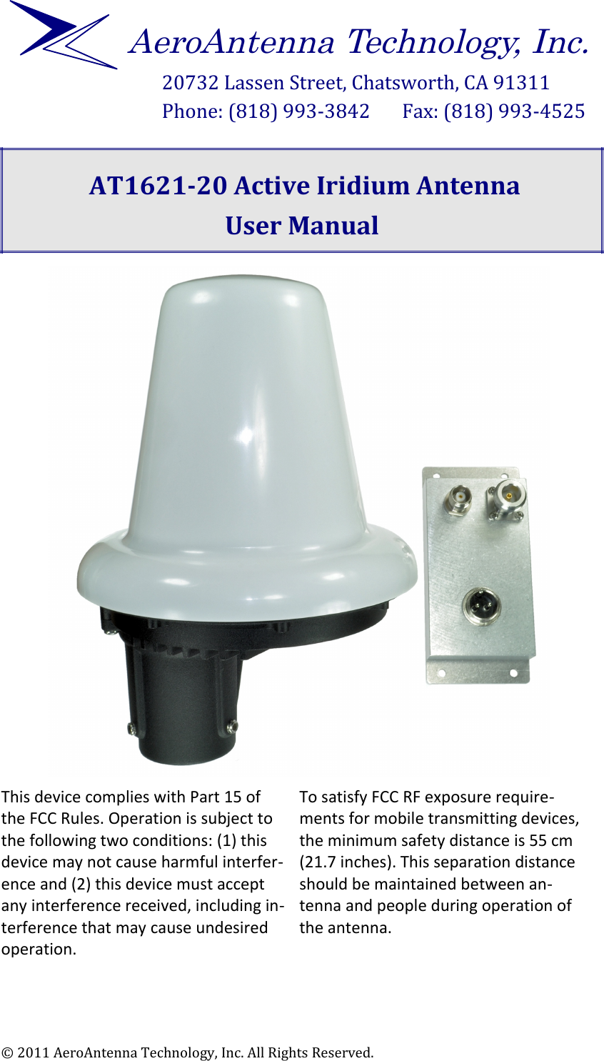
AeroAntenna Technology AT1621-20 ACTIVE IRIDIUM ANTENNA User Manual

AeroAntenna Technology, Inc. ACTIVE IRIDIUM ANTENNA Users Manual

Users Manual

20732 Lassen Street, Chatsworth, CA 91311Phone: (818) 993-3842       Fax: (818) 993-4525  AT1621-20 Active Iridium AntennaUser Manual This device complies with Part 15 of the FCC Rules. Operation is subject to the following two conditions: (1) this device may not cause harmful interfer$ence and (2) this device must accept any interference received, including in$terference that may cause undesired operation. To satisfy FCC RF exposure require$ments for mobile transmitting devices, the minimum safety distance is 55 cm (21.7 inches). This separation distance should be maintained between an$tenna and people during operation of the antenna. © 2011 AeroAntenna Technology, Inc. All Rights Reserved.AeroAntenna Technology, Inc.
AT1621-20 Active Iridium Antenna User Manual                            Rev 1 17 Jan 2011Rev HistoryRev Changes1•First version. ••Table of Contents1 Introduction............................................................................................................................... 32 Important Safety Information Regarding Exposure to RF Signals......................33 Cable Length Requirements................................................................................................ 34 Antenna Kit Contents............................................................................................................. 45 Connecting Your Antenna.................................................................................................... 45.1 Outside/Above Decks.................................................................................................... 55.1.1 Bring long RF cable to top of pole or mast...............................................55.1.2 Feed cable through mounting bracket and attach TNC connector to antenna.......................................................................................................................... 55.1.3 Screw in Mounting Screws to affix mounting bracket to antenna. 65.1.4 Place mounting bracket over pole and tighten set screws................65.2 Inside/Below Decks....................................................................................................... 75.2.1 Attach Type N connector from long RF cable to bias box..................75.2.2 Attach short RF cable to bias box and phone/docking station........85.2.3 Connect DC power (9 to 36 VDC, 30W max) to bias box. ..................96 Specifications.......................................................................................................................... 10© 2012 AeroAntenna Technology, Inc. All Rights Reserved. page 2 of 10
AT1621-20 Active Iridium Antenna User Manual                            Rev 1 17 Jan 20111 IntroductionThe AT1621-20 antenna is designed for Iridium applications where long RF cables are needed and a passive antenna cannot be used. The AT1621-20 has an integrated power amplifier (for transmitting signals to the satellite) and low noise amplifier (for receiving signals from the satellite)2 Important   Safety   Information   Regarding   Exposure   to   RF SignalsWARNING To satisfy FCC RF exposure requirements for mobiletransmitting devices, the minimum safety distance is55 cm (21.7 inches). This separation distance shouldbe maintained between antenna and people duringoperation of the antenna. 3 Cable Length RequirementsTo meet Iridium performance requirements and comply with FCC regulations, care must be taken to use the appropriate total RF cable length. Your antenna distributor should provide the appropriate cable. Total Cable Loss Requirement  13.3 dB total for two cablesReference CableSet     5 ft (1.5 m) RG58LL    1.1 dB loss @1621 MHz115 ft (35 m) LMR240 12.2 dB loss @ 1621 MHz© 2012 AeroAntenna Technology, Inc. All Rights Reserved. page 3 of 10WARNINGMICROWAVE RADIATIONMINIMUM SAFE DISTANCE0.55 METRES
AT1621-20 Active Iridium Antenna User Manual                            Rev 1 17 Jan 20114 Antenna Kit ContentsDCANTPHONEWARNINGMICRO WAVE RADIATIONMINIMUM SAFE DIS TANCE0.55 METRES13245671.4 in(35.6 mm)4 in(101.6 mm)1.4 in ID MAX(35.6 mm) antenna bias box mounting bracket set screws (3) mounting screws (3) flat washers (3) split washers(3) 5 Connecting Your AntennaWARNING To satisfy FCC RF exposure requirements for mobiletransmitting devices, the minimum safety distance is55 cm (21.7 inches). This separation distance shouldbe maintained between antenna and people duringoperation of the antenna. © 2012 AeroAntenna Technology, Inc. All Rights Reserved. page 4 of 10WARNINGMICROWAVE RADIATIONMINIMUM SAFE DISTANCE0.55 METRES
AT1621-20 Active Iridium Antenna User Manual                            Rev 1 1 Aug 20115.1 Outside/Above Decks5.1.1 Bring long RF cable to top of pole or mast5.1.2 Feed cable through mounting bracket and attach TNC connector to antenna© 2011 AeroAntenna Technology, Inc. All Rights Reserved. page 5 of 10TNCto bias boxWARNINGMICROWAVE RADIATIONMINIMUM SAFE DISTANCE0.55 METRESType Nantennapipe/ mastmountingbracketto antennaTNClong RF cablepipe/ mastType Nto bias box
AT1621-20 Active Iridium Antenna User Manual                            Rev 1 1 Aug 20115.1.3 Screw in Mounting Screws to affix mounting bracket to antenna5.1.4 Place   mounting   bracket   over pole and tighten set screws.© 2011 AeroAntenna Technology, Inc. All Rights Reserved. page 6 of 10to bias boxType NWARNINGMICROWAVE RADIATIONMINIMUM SAFE DISTANCE0.55 METRESantennaWARNINGMICROWAVE RADIATIONMINIMUM SAFE DISTANCE0.55 METRESType Nto bias boxantennapipe/ mastmountingbracket
AT1621-20 Active Iridium Antenna User Manual                            Rev 1 1 Aug 20115.2 Inside/Below Decks5.2.1 Attach Type N connector from long RF cable to bias box.© 2011 AeroAntenna Technology, Inc. All Rights Reserved. page 7 of 10Type NWARNINGMICROWAVE RADIATIONMINIMUM SAFE DISTANCE0.55 METRESDCANTPHONEbias boxantenna
AT1621-20 Active Iridium Antenna User Manual                            Rev 1 17 Jan 20115.2.2 Attach short RF cable to bias box and phone/docking station.© 2012 AeroAntenna Technology, Inc. All Rights Reserved. page 8 of 10WARNINGMICROWAVE RADIATIONMINIMUM SAFE DISTANCE0.55 METRESDCANTPHONETNCTNC1GHI4PQRS758069JKLTUVMNOWXYZABC DEF23bias boxantenna
AT1621-20 Active Iridium Antenna User Manual                            Rev 1 17 Jan 20115.2.3 Connect DC power (9 to 36 VDC, 30W max) to bias box. © 2012 AeroAntenna Technology, Inc. All Rights Reserved. page 9 of 10bias boxWARNINGMICROWAVE RADIATIONMINIMUM SAFE DISTANCE0.55 METRESDCANTPHONEto AC/DC adapter orother DC source antennaPhilmore P602C1GHI4PQRS758069JKLTUVMNOWXYZABC DEF23
AT1621-20 Active Iridium Antenna User Manual                            Rev 1 17 Jan 20116 SpecificationsEQUIPMENT TYPE  Mobile or Fixed Base Station INTEGRATED OPERATING ENVIRON-MENT [ x ] Commercial [ x ] Light Industry & Heavy Industry POWER SUPPLY REQUIREMENT 9 to 36V DC, 30W maximum RF INPUT POWER RATING (US & CANADA) 29 dBm or 0.8 Watt peak (conducted) EIRP 12.31 dBW MaxDUTY CYCLE  N/A TX OPERATING FREQUENCY RANGE  1616.0 - 1626.5 MHz RX OPERATING FREQUENCY RANGE  1616.0 - 1626.5 MHz RF INPUT IMPEDANCE  50 Ohms MODULATION  Q7WEMISSION DESIGNATION 96K1Q7WANTENNA TYPE  Integral ANTENNA CONNECTOR TYPE  TNC Female TEMPERATURE RATING     STORAGE:     OPERATIONAL: -40°C to +80°C -25°C to +55°C © 2012 AeroAntenna Technology, Inc. All Rights Reserved. page 10 of 10

Navigation menu