AeroComm 514830111 Cellular Over Fiber Cell Extender System User Manual Manual
Aerocomm Inc Cellular Over Fiber Cell Extender System Manual
AeroComm >
Manual

CELLULAR FIBER OPTICAL
EXTENDER
(Donor & Server Units)
OPERATION
INSTRUCTION MANUAL
MODEL 51483-C
MD Office:
19516 Amaranth Drive
Germantown, MD 20874
Phone: 301-540-0700
Fax: 301-540-5743
NJ Office:
464 Hudson Terrace
Englewood Cliffs, NJ 07632
Phone: 201-227-0066
Fax: 201-227-0067
Email: mail@aerocomminc.com
http://www.aerocomminc.com
ALL INFORMATION CONTAINED IN THIS DOCUMENT IS PROPRIETARY TO AEROCOMM, AND
SHALL NOT BE RELEASED, DISCLOSED OR DUPLICATED FOR ANY PURPOSE OTHER THEN
EVALUATION, INSPECTION, OR MAINTENANCE OF EQUIPMENT DELINEATED HEREIN.
AEROCOMM IS NOT RESPONSIBLE FOR ANY EQUIPMENT REPAIRED OR ALTERED BY PERSONS
NOT AUTHORIZED BY AEROCOMM, OR NOT IN ACCORDANCE WITH INSTRUCTIONS FURNISHED
BY AEROCOMM. AEROCOMM IS NOT RESPONSIBLE FOR EQUIPMENT RENDERED DEFECTIVE AS
A RESULT OF MISUSE, IMPROPER REPAIR, OR ABNORMAL CONDITIONS OF OPERATION, NOR
DOES AEROCOMM ASSUME ANY LIABILITY FOR ANY CONSEQUENTIAL DAMAGE CAUSED BY
SUCH EQUIPMENT.
SERVICE CONTRACTS OR CUSTOMER ASSISTANCE AGREEMENTS ARE AVAILABLE FOR
AEROCOMM PRODUCTS THAT REQUIRE MAINTENANCE AND/OR REPAIR. AEROCOMM ALSO
HAS AVAILABLE SERVICE AND CONSULTATION CONTRACTS FOR ENTIRE SYSTEMS
CONFIGURATION.
2
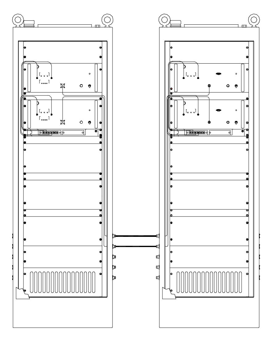
CELLULAR FIBER OPTICAL
EXTENDER
MODEL 51483-C
(824-849MHz: 869-894MHz)
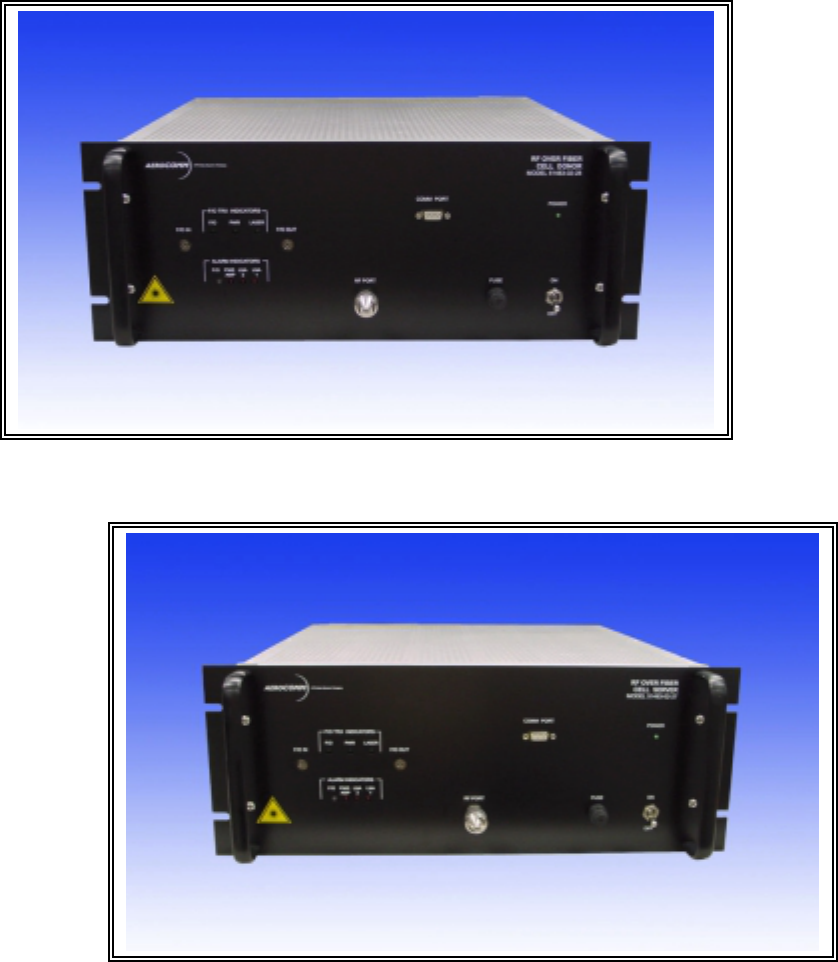
AEROCOMM
AEROCOMM SMR SERVER
RF O VER FIBER
MO DE L 51 081 -02 -47
RF OUT
F/O T RX I NDI CATORS
LA SE R
LN A
ALARM INDICATORS
A Wireless Systems Company
FO IN
21
F/ O
PW R
AM P
F/ O LN A
PW R
FO OUT
OFF
POWE R
OFF
ONFU SE
PCS SER VER
RF O VER FIBER
MO DE L 51 081 -02 -45
RF OUT
F/O T RX I NDI CATORS
LA SE R
LN A
ALARM INDICATORS
A Wireless Systems Company
FO IN
21
PW R
AM P
F/ O
F/ O
PW R
LN A
FO OUT
ON
POWE R
FU SE
AEROCOMMA Wireless Systems Co mpany
LA SE RPW R
FO IN
F/ O
F/O T RX I NDI CATORS
FO OUT
RF IN
BTS
INT ERFA CE
MO DE L 51 081 -02 -47
RF O VER FIBER
OFF
SM R SERVER
ON
OFF
POWE R
FU SE
AEROCOMM
LA SE RPW R
A Wireless Systems Company
FO IN
F/ O
F/O T RX I NDI CATORS
FO OUT
RF IN
BTS
INT ERFA CE
MO DE L 51 081 -02 -45
RF O VER FIBER
POWE R
ON
PCS SER VER
FU SE
DONOR SERVER

3
TABLE OF CONTENTS
I. INTRODUCTION...........................................................................................................4
PURPOSE OF MANUAL:..............................................................................................4
MANUAL OUTLINE .....................................................................................................4
GENERAL SYSTEM OVERVIEW:..............................................................................5
II. SPECIFICATIONS.........................................................................................................6
GENERAL SPECIFICATIONS......................................................................................6
Service: CELLULAR..................................................................................................6
SUB-ASSEMBLY SPECIFICATIONS:.........................................................................7
AC231 ....................................................................... Error! Bookmark not defined.
51099 LNA..................................................................................................................8
51211 LNA..................................................................................................................8
51098 LNA..................................................................................................................9
20dB Attenuator..........................................................................................................9
6dB Attenuator............................................................................................................9
Duplexer....................................................................................................................10
TX Filter....................................................................................................................10
RX Filter....................................................................................................................10
III. INSTALLATION.......................................................................................................11
RF CABLE CONNECTIONS.......................................................................................11
FIBER OPTICAL CABLE CONNECTIONS...............................................................11
IV. OPERATION OF EQUIPMENT...............................................................................12
V. MAINTENANCE SCHEDULE...................................................................................13
CABLE INSPECTIONS:..............................................................................................13
ENCLOSURE INSPECTIONS:....................................................................................13
LED INSPECTIONS:....................................................................................................13
VI. THEORY OF OPERATION......................................................................................14
VII. TROUBLESHOOTING............................................................................................15
SERVER UNIT..............................................................................................................15
DONOR UNIT ..............................................................................................................16
VIII. RECOMMENDED SPARES..................................................................................17
4
I. INTRODUCTION
PURPOSE OF MANUAL:
The purpose of this manual is to outline the installation, describe the operation,
and assist in the maintenance and trouble-shooting of the CELLULAR Fiber Optical
Extender, Model 51483-C.
MANUAL OUTLINE
Section II: Section II covers the general specification of the CELLULAR
Fiber Optical Extender. This section outlines the general, mechanical and
electrical specifications including the module specifications (sub-assemblies).
Section III: Section III covers the instructions for installing the CELLULAR
Fiber Optical Extender, site requirements, and equipment initialization.
Section IV: Section IV covers Operation of Equipment.
Section V: Section V is the recommended schedule of periodic maintenance of
CELLULAR Fiber Optical Extender.
Section VI: Section VI covers the general “Theory of Operations” of the logic
and modules of CELLULAR Fiber Optical Extender. This section is designed to
aid in understanding of the CELLULAR Fiber Optical Extender.
Section VII: Section VII consists of diagrams, tables and procedures to assist in
the troubleshooting of a CELLULAR Fiber Optical Extender. This section is
designed to guide a technician in locating system fault(s) to the module. Included
in the section is a list of recommended test equipment.
Section VIII: Section VIII lists the recommended spare parts for the
CELLULAR Fiber Optical Extender.
5
GENERAL SYSTEM OVERVIEW:
The AeroComm, Inc. Fiber Optic Booster Amplifier (Model#51483-C) can be
used where CELLULAR Carrier Service is required but not accessible due to long or
difficult coaxial cable runs. It eliminates costly construction using coaxial cable. The
AeroComm, Inc. Model#51483-C converts the Carrier RF signal, enabling the use of
Fiber Optic Cable which is easily routed to inaccessible areas and has much lower loss,
where it is then reconverted back to Carrier RF signal.

6
II. SPECIFICATIONS
GENERAL SPECIFICATIONS
Service: CELLULAR
Frequency Range: Uplink: 824-849 MHz Downlink: 869-894 MHz
Noise Figure: 6.3 dB Typical 7.0dB Typical
Gain: 51 dB Min. 51dB Min.
Delay: 5usec/Km
Output Power: +22 dBm +23 dBm
Input Power (No Damage): -30 dBm Max -30 dBm Max
Power Consumption: 1.2 A @ 110 VAC Per Donor/Server
Weight: 21 lbs.
Temperature: -25C to + 75 C
Size: 19” Rack Mount Unit, 4U (7”H) x 18”
RF Connectors: N-Female
Fiber Optic Connectors: FC/APC
Cable: 9/125 mm Single Mode FO Cable
Enclosure: 19” Rack Mount

7
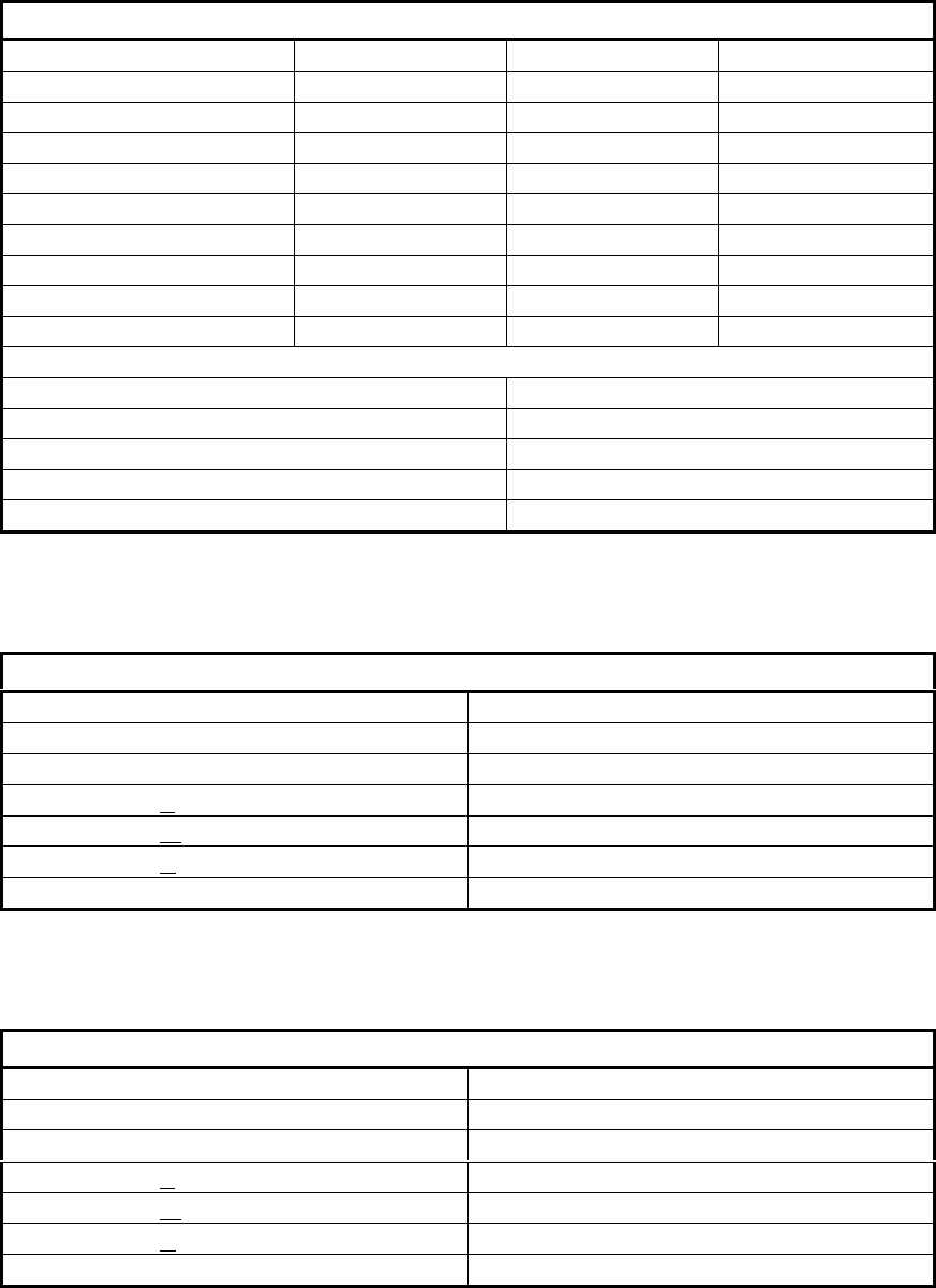
SUB-ASSEMBLY SPECIFICATIONS:
RF TO FIBER MODULE
Parameter Min Typical Max
Wavelength, peak: 1520nm
1280nm 1550nm
1310nm 1570nm
1360nm
Bandwidth: 50MHZ 2000MHZ
Frequency Flatness:
(800-2000MHZ) + / - 1.5dB
In & Out VSWR: 1.5:1 1.8:1
RF Isolation, In-band: 40
Spur Free Dynamic Range: 103dB/HZ 3/2 106dB/HZ 3/2
RF Link Gain: -2dB 0dB +2dB
Noise Figure WM option
WA option
WB option
34dB
38dB
42dB
Input 3rd Order Intercept
WM option
WA option
WB option
+22dBm
+26dBm
+29dBm
Absolute Maximums
Operating Temperature: -30°C to +75°C
Storage Temperature: -40°C to +85°C
Maximum RF Input to Transmitter: +10dBm
Maximum Optical Input to Receiver: 4mW
D.C. Supply Voltage: 12 volts +\-5%

8
51099 LNA
Parameter Min Typical Max
Gain: 13dB 14.5dB
Noise Figure: 1.5dB 1.8dB
VSWR: 1.5:1 / 1.3:1
OP1dB: +16.5dBm
Input IP3: +15dBm
Reverse Isolation: 23dB
Bias Current: 50mA 100mA
Input Voltage: +10VDC +15VDC +30VDC
Absolute Maximum Ratings
Input Power: +17dBm
Operating Temperature: -30°C to +60°C
Storage Temperature: -40°C to +85°C
51211 LNA
Parameter Min Typical Max
Gain: 35dB 36dB
Gain Flatness: +/- 0.5dB +/- 1dB +/- 1.2dB
Noise Figure: 1.35dB 1.5dB
In / Out VSWR: 1.5:1 / 1.2:1
OP1dB: +22.5dBm +23dBm
Input IP3: +36dBm +41dBm
Reverse Isolation: 45dB
Bias Current: 125mA 200mA
Input Voltage: +10VDC +13.5VDC +17VDC
Absolute Maximum Ratings
Input Power: +17dBm
Operating Temperature: -30°C to +60°C
Storage Temperature: -40°C to +85°C
9
51098 Power AMP
Parameter Min Typical Max
Gain: 28.5dB 30dB 31dB
Gain Flatness: +/- 0.4dB +/- 1.2dB
Noise Figure: 2.3dB 3.7dB
In / Out VSWR: 1.5:1 / 1.2:1
OP1dB: +35dB +36dBm
Input IP3: +50dbm +52dBm
Input Voltage: +12VDC +13.5VDC +18VDC
Bias Current: 1600mA 2000mA
Operating Temperature -20°C +60°C
Absolute Maximum Ratings
VCC: +20VDC
Input Power: +5dBm
Current: 2200mA
Operating Temperature: -30°C to +70°C
Storage Temperature: -40°C to +85°C
20dB Attenuator
P/N: BW-S20W2
Frequency: DC-18GHZ
Accuracy: ±0.60
VSWR: L DC-4GHZ 1.20
M 4-8GHZ 1.25
U 8-12.4GHZ 1.30
Power: 2W
6dB Attenuator
P/N: BW-S6W2
Frequency: DC-18GHZ
Accuracy: ±0.40
VSWR: L DC-4GH 1.20
M4-8GH 1.25
U 8-12.4GHZ 1.30
Power: 2Watts

10
Duplexer
P/N: 60024
Receive: 821-851MHz
Transmit: 866-895MHz
Passband Insertion Loss: 1.0dB maximum
Channel to Channel Isolation: 65dB minimum
Maximum Transmit Power Handling:
CW 20 watts
Peak Instantaneous 80 watts
Passband Return Loss: 15dB minimum
Operating Temperature: -30 to +70°C
Dimensions: 2.00”W x 2.97”D x 5.00”H
Connectors: SMA- Female
TX Filter
P/N: 5BCR12C-882.5/33-D
Passband: 869-894MHZ
3dB Passband: 34MHZ
Passband Insertion Loss: 2.5dB maximum
Rejection:
DC - 849MHZ 60dB minimum
849 - 859MHZ 30dB minimum
914 – 3xFoMHZ 40dB minimum
Passband Return Loss: 15dB minimum
VSWR: 1.5:1 max.
Connectors: SMA- Female
RX Filter
P/N: 5BCR12C-840.5/33-D
Passband: 826-851MHZ
3dB Passband: 34MHZ
Passband Insertion Loss: 2.5dB maximum
Rejection:
DC - 806MHZ 60dB minimum
806 - 816MHZ 30dB minimum
871 - 3xFoMHZ 40dB minimum
Passband Return Loss: 15dB minimum
VSWR: 1.5:1 max.
Connectors: SMA- Female
11
III. INSTALLATION
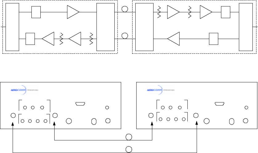
The CELLULAR Fiber Optical Extender is housed in a 19” Rack Mount
enclosure. Refer to Figure 1 for the installation block diagram.
RF CABLE CONNECTIONS
! The RF cable from Donor Antenna to the DONOR UNIT is connected to female N-
Type Connector on the CELLULAR DONOR front panel RF PORT.
! The RF cable from Server Antenna to the SERVER UNIT is connected to female N-
Type Connector on the CELLULAR SERVER front panel RF PORT.
FIBER OPTICAL CABLE CONNECTIONS
The FC/APC to FC/APC fiber cables is connected between Donor and Server front panel.
! Donor FO OUT connects to the Server FO IN.
! Donor FO IN connects to the Server FO OUT.
" Caution: The FC/APC Fiber Optic connector is a Keyed connector, if the Key is not
mated properly the connector will not mate. Extreme caution must be maintained to
avoid touching the end of the fiber optic connector and getting it dirty.
" Coaxial and Fiber Optic cables are supplied by user.
AC POWER CONNECTIONS
Connect AC Line Cord to the 110VAC Power Sources.
D uplexer
TX
RX
FO
INPUT
FO
OU TPUT
RF
INPUT
RF
OU TPUT
D uplexer
TX
RX
RF
INPUT
RF
OU TPUT
FO
INPUT FO
OU TPUT
RF / FO
Tranceiver
Anacom
A C231
RF / FO
Tranceiver
Anacom
A C231
51211
51211
RX Filter RX Filter
TX Filter TX Filter
51099
51099 51098
51098
20dB ATT
20dB ATT 6dB ATT
6dB ATT
LNA Aerocom m
LNA Aerocom m
LNA Aerocom m Power AM P
Aerocom m
Power AM P
Aerocom m
DONOR UNIT SERV ER UNIT
CELLULAR FOEX
BLOCK DIAGRAM
D onor Antenna
Server Antenna
F/O TRX INDICATORS
FO OUTFO IN
RF PORT
F/O PWR LASER
FUSE ON
OFF
F/O TRX INDICATORS
FO OUTFO IN
RF PORT
F/O PWR LASER
FUSE ON
OFF
ALARM INDICATORS
F/O PWR LNA LNA
AMP 2 1
RF OVER FIBER
CELL SERVER
MODEL 51483-02-27
PO WE R
PO WE R
RF OVER FIBER
CEL L DO NO R
MODEL 51483-02-28
F/O PWR LNA LNA
AMP 2 1
COMM PORT COMM PORT
FIGURE 1
12
IV. OPERATION OF EQUIPMENT
The CELLULAR Fiber Optical Extender requires no operator settings for
operation. It is designed for unattended operation.
The following is all that is necessary for operation:
# Install
# Connect
# Turn-On
# Watch LED
13
V. MAINTENANCE SCHEDULE
The CELLULAR Fiber Optical Extender is designed for unattended operation
requiring minimal maintenance. General maintenance consists of equipment inspection
and operational tests. Periodical equipment tune-up and alignment is recommended.
CABLE INSPECTIONS:
The external and internal cables and connectors should be checked for
indication of corrosion.
ENCLOSURE INSPECTIONS:
The interior of the enclosures should be inspected for evidence of
condensation.
LED INSPECTIONS:
DONOR UNIT
# POWER LED: ON
# F/O TRX INDICATORS
F/O LED: ON
PWR LED: ON
LASER LED: ON
# ALARM INDICATORS
F/O LED: GREEN
PWR AMP LED: OFF
LNA2 LED: OFF
LNA1 LED: OFF
# COMM PORT
Normal: Closed (Pin1 & Pin2)
Fault: Open (Pin1 & Pin2)
SERVER UNIT
# POWER LED: ON
# F/O TRX INDICATORS
F/O LED: ON
PWR LED: ON
LASER LED: ON
# ALARM INDICATORS
F/O LED: GREEN
PWR AMP LED: OFF
LNA2 LED: OFF
LNA1 LED: OFF
# COMM PORT
Normal: Closed (Pin1 & Pin2)
Fault: Open (Pin1 & Pin2)
The performance of operations testing is recommended to be done semi-annually.
Operational testing will indicate equipment status, determining if an alignment is
necessary.
14
VI. THEORY OF OPERATION
The CELLULAR Fiber Optical Extender has two channels, one is Down Link
frequencies from 869MHZ to 894MHZ, and the other is UP Link frequencies from
824MHZ to 849MHZ. Both Up Link and Down Link signals are converted from RF
signals to optical signals then through the fiber optical cable to the far end and converted
back to RF signals. The AeroComm, Inc. Fiber Optic Booster Amplifier (Model#51483-
C) can be used where CELLULAR Carrier Service is required but not accessible due to
long or difficult coaxial cable runs. It eliminates costly construction using coaxial cable.
The AeroComm, Inc. Model# 51483-C converts the Carrier RF signal to optical signals,
enabling the use of Fiber Optic Cable which is easily routed to inaccessible areas and has
much lower loss, where it is then reconverted back to Carrier RF signal.
Caution: The user that changes or modifications not expressly approved by the party
responsible for compliance could void the user’s authority to operate the device (CFR 47
section 15.2)
NOTE: This equipment has been tested and found to comply with the limits for a Class
A digital device, pursuant to part 15 of the FCC Rules. These limits are designed to
provide reasonable protection against harmful interference when the equipment is
operated in commercial environment. This equipment generates, uses and can radiate
radio frequency energy and, if not installed and used in accordance with the instruction
manual, may cause harmful interference to radio communications. Operation of this
equipment in a residential area is likely to case harmful interference in which case the
user will be required to correct the interference at this own expense.

15
VII. TROUBLESHOOTING
This Troubleshooting Procedure has been developed for the use of a trained
technician with knowledge of troubleshooting methodology in order to isolate faults to
the unit level.
SERVER UNIT
Problem Solution
1. Power LED is off a) Check Fuse, if fuse is ok go to next step.
b) Check Power Supply 110VAC input, if 110VAC is
present, go to next step.
c) Check Power Supply +12VDC output. If +12 volt is not
present, replace the Server Unit.
2. PWR LED is off
(F/O TRX INDICATORS) a) Replace the Server Unit.
3. LASER LED is off
(F/O TRX INDICATORS) a) Replace the Server Unit.
4. F/O LED is off
(F/O TRX INDICATORS) a) to Problem 8.
5. LNA1 LED is on
(ALARM INDICATORS) a) Replace the Server Unit.
6. LNA2 LED is on
(ALARM INDICATORS) a) Replace the Server Unit.
7. PWR AMP LED is on
(ALARM INDICATORS) a) Replace the Server Unit.
8. F/O LED is red
(ALARM INDICATORS) a) Check the FC/APC Connectors and insure they are
mated properly. Using a cotton swab cleaner, and alcohol
clean the FC/APC connector. If F/O LED is still red, go
to next step.
b) Using a short FC/APC to FC/APC Fiber Optic
Patchcord connect between FO IN and FO OUT. If LED
is still red, replace the Server Unit. If LED is green go to
next step.
b) Check Fiber Optic Cable by using Fiber Test Meter, if
Fiber Optic Cable is ok, the problem is on the Donor
Unit.

16
DONOR UNIT
Problem Solution
1. Power LED is off a) Check Fuse, if fuse is ok go to next step.
b) Check Power Supply 110VAC input, if 110VAC is
present, go to next step.
c) Check Power Supply +12VDC output. If +12 volt is not
present, replace the Donor Unit.
2. PWR LED is off
(F/O TRX INDICATORS) a) Replace the Donor Unit.
3. LASER LED is off
(F/O TRX INDICATORS) a) Replace the Donor Unit.
4. F/O LED is off
(F/O TRX INDICATORS) a) to Problem 8.
5. LNA1 LED is on
(ALARM INDICATORS) a) Replace the Donor Unit.
6. LNA2 LED is on
(ALARM INDICATORS) a) Replace the Donor Unit.
7. PWR AMP LED is on
(ALARM INDICATORS) a) Replace the Donor Unit.
8. F/O LED is red
(ALARM INDICATORS) a) Check the FC/APC Connectors and insure they are
mated properly. Using a cotton swab cleaner, and alcohol
clean the FC/APC connector. If F/O LED is still red, go
to next step.
b) Using a short FC/APC to FC/APC Fiber Optic
Patchcord connect between FO IN and FO OUT. If LED
is still red replace the Donor Unit. If LED is green go to
next step.
b) Check Fiber Optic Cable by using Fiber Test Meter, if
Fiber Optic Cable is ok, the problem is on the Server
Unit.
17
VIII. RECOMMENDED SPARES
We recommend units be sent to factory for repair or replacement.