AeroScout EX5210 Exciter - EX5210, EX5210R User Manual EX5210R Exciter Installation Configuration Guide
AeroScout Exciter - EX5210, EX5210R EX5210R Exciter Installation Configuration Guide
User Manual

EX5210R RUGGED EXCITER
INSTALLATION & CONFIGURATION GUIDE
DRAFT 1: Updated 2018/10/10

Disclaimer
The information and know-how included in this document are the exclusive property of STANLEY
Healthcare and are intended for the use of the addressee or the user alone. The addressees shall
not forward to another their right of using the information, know-how or document forwarded
herewith, in whole or in part in all matters relating or stemming from or involved therein,
whether for consideration or without consideration, and shall not permit any third party to utilize
the information, know-how or the documents forwarded herewith or copies or duplicates
thereof, unless at the company’s consent in advance and in writing. Any distribution,
advertisement, copying or duplication in any form whatsoever is absolutely prohibited. The
Company reserves the right to sue the addressee, user and/or any one on their behalves, as well as
third parties, in respect to breaching its rights pertaining to the intellectual rights in particular
and its rights of whatever kind or type in the information, know-how or the documents
forwarded by them herewith in general, whether by act or by omission.
This document is confidential and proprietary to STANLEY Healthcare and is not to be distributed
to any persons other than licensed AeroScout Visibility System users or other persons appointed in
writing by STANLEY Healthcare.
Trademark Acknowledgements
AeroScout is a trademark of Stanley Black & Decker, Inc. or its affiliates. Other brand products and
service names are trademarks or registered trademarks of their respective holders. Below is a
partial listing of other trademarks or registered trademarks referenced herein:
Cisco™ is a trademark of Cisco Systems, Inc.
Sun, Sun Microsystems, the Sun Logo, Java, JRE and all other Sun trademarks, logos, product
names, service names, program names and slogans that are referred to or displayed in this
document are trademarks or registered trademarks of Sun Microsystems, Inc. in the United States
and other countries.
This product includes software developed by the Apache Software Foundation
(http://www.apache.org/).
This product includes code licensed from RSA Data Security
Skype, SkypeIn, SkypeOut, Skype Me, the Skype Logo and the S logo and other marks indicated on
Skype’s website are trademarks of Skype Limited or other related companies.
Esper is a trademark of EsperTech, Inc.
Jboss is a trademark of Red Hat Middleware, LLC.
Oracle 10G is a registered trademark of Oracle Corporation and/or its affiliates.
MS SQL Server is a registered trademark of Microsoft Corporation in the United States and/or
other countries.
JasperSoft, the JasperSoft Logo, JasperReports, the JasperReports logo, JasperIntelligence,
JasperDecisions, JasperAnalysis, Scope Center, Scope Designer, and JasperServer are trademarks or
registered trademarks of JasperSoft, Inc. in the United States and other countries.
©2018 STANLEY Healthcare. All rights reserved.
Doc: 0981-xxx-000 REV A. Published: Draft1. KB Article: xxxxx.

EX5210R Exciter Installation & Configuration Guide
3
Table of Contents
Introduction .................................................................................................. 5
Exciter Applications and Industry Examples .............................................. 6
Theft Prevention .................................................................................................. 6
Process Control ..................................................................................................... 6
Automatic Inventory Management ..................................................................... 6
Real-Time Alerts ................................................................................................... 6
Security applications ............................................................................................ 6
Exciter Features ............................................................................................. 7
RFID Detection of STANLEY Healthcare Tags ...................................................... 7
Tag Behavior Modification .................................................................................. 7
Message Programming Functions ........................................................................ 8
Network Connectivity .......................................................................................... 8
Chaining ............................................................................................................... 8
LED Status Indicators .................................................................................... 9
Exciter Connector Panel ............................................................................. 10
Wiring the Exciter ....................................................................................... 12
LF Coverage ................................................................................................. 13
Network and Power Connections .............................................................. 14
Direct Power Supply ........................................................................................... 15
PoE Switch .......................................................................................................... 15
110/220 VAC to 48 VDC PoE Single-Port Injector .............................................. 16
Power Connection Summary .............................................................................. 17
Chaining EX5210R Exciters ......................................................................... 18
EX5210R Chain Connection................................................................................ 18
Configuring Chained Exciters ............................................................................ 19
Configurations for Engine 5.2 and below ....................................................................19
Configurations for Engine 5.3 and above ....................................................................21
DHCP ............................................................................................................. 23

EX5210R Exciter Installation & Configuration Guide
4
Resetting the Exciter IP Address ................................................................ 24
Mounting the Exciter .................................................................................. 25
Fixing the Exciter to a Wall/Ceiling .................................................................... 25
Mounting the Exciter to a Poll ........................................................................... 27
Appendix A: Exciter and Accessories ........................................................ 28
Appendix B: Exciter Specifications ............................................................ 29
EX5210R Exciter Installation & Configuration Guide
5
Introduction
The EX5210R Rugged Exciter is a component of the STANLEY Healthcare suite of
enterprise-level visibility solutions based on standard Wi-Fi wireless
communications for location- based applications. The EX5210R Exciter is
designed for outdoor mounting, providing robust and sophisticated RFID
detection capabilities.
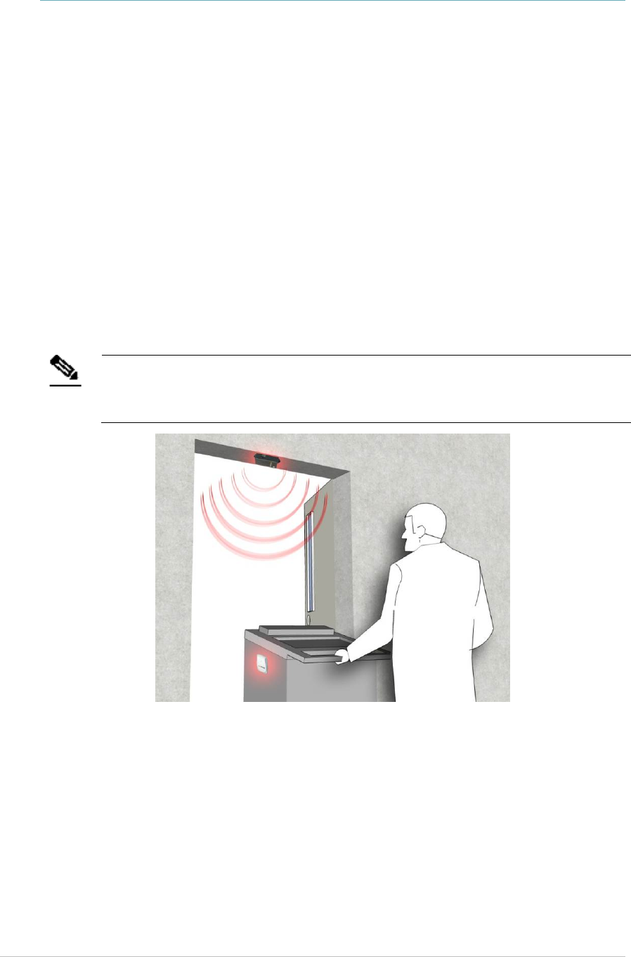
The EX5210R Exciter triggers tags as they pass through a chokepoint or as they
approach the Exciter. Tags in turn transmit a message to either the AeroScout
Location Receivers or to compatible Access Points within range. The Exciter can
activate or deactivate tags, program them, or even instruct the tags to operate
in a specific way (for example, to blink). This provides instant acknowledgment
that a tagged asset has passed through a gate, doorway, or other specifically
defined area. The detection capabilities of the EX5210R Exciter combined with
the location features of the AeroScout Location Engine, to make the STANLEY
Healthcare suite the most sophisticated enterprise visibility solution, for various
applications.
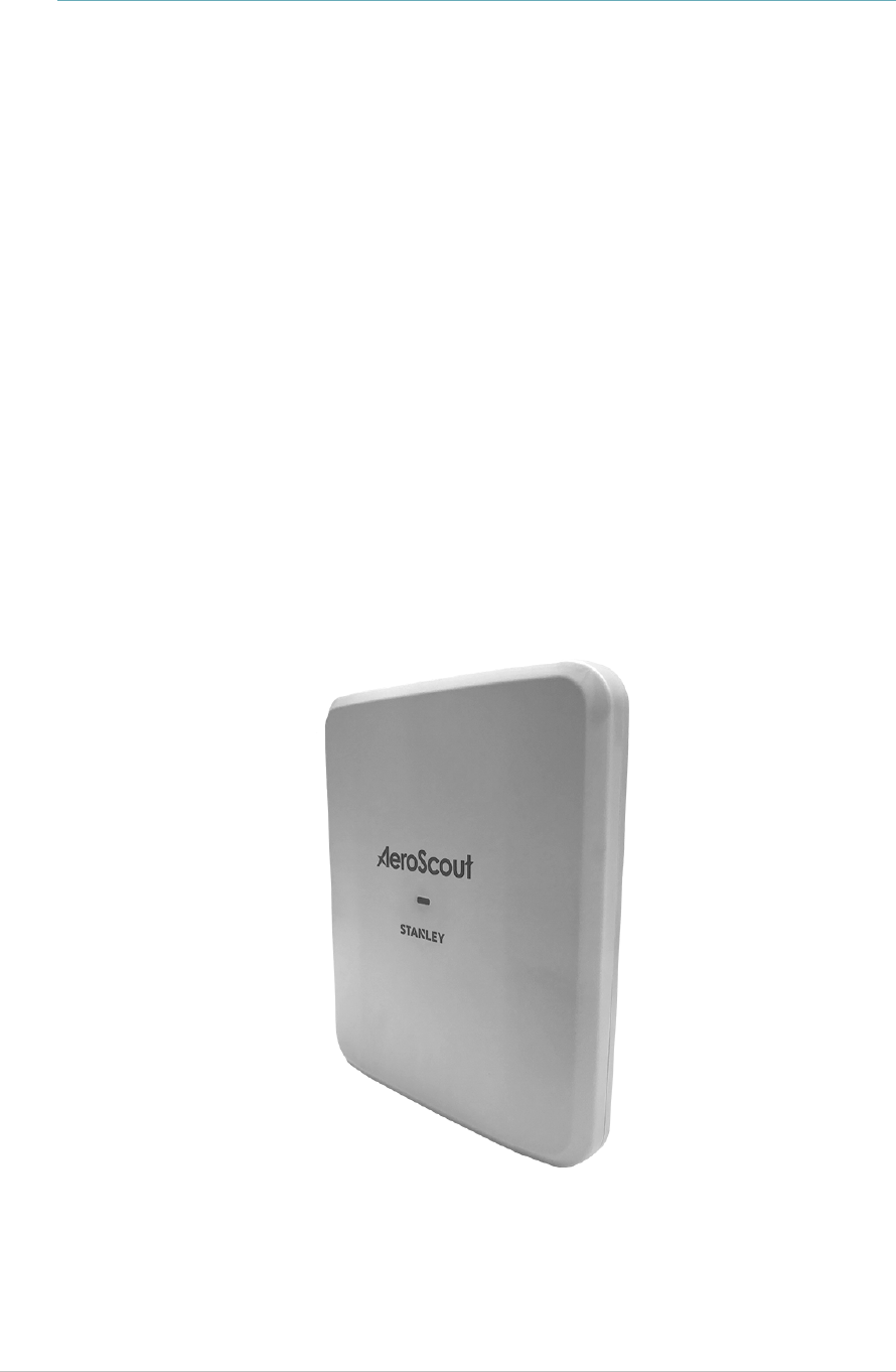
Figure 1: EX5210R Exciter

EX5210R Exciter Installation & Configuration Guide
6
Exciter Applications and Industry
Examples
Theft Prevention
Healthcare organizations or enterprises with expensive and mission-critical
equipment can tag valuable assets that are intended to remain within a
specified area. The AeroScout System can track the location of such items and
trigger an alert when they pass through an exit point or enter a restricted area.
Process Control
Manufacturing companies can track the location of equipment, carriers, and the
work-in-process (WIP) inventory during a production cycle. This provides a real-
time view of the production line. The type and quantity of products can be
tracked through each step in the process.
Automatic Inventory Management
Logistics organizations can update inventory records by automatically
determining assets within defined areas, ensuring real-time knowledge of
inventory levels without manual checks or barcode scanning.
Real-Time Alerts
Organizations can use the Exciters to trigger automated events and alerts based
on the current location of an asset. For example, in a shipping yard,
notifications can be sent when vehicles pass through gates and enter or exit a
certain dock or bonded area.
Security applications
Exciters can be installed at the entrances of restricted areas to trigger alerts
when unauthorized persons attempt to enter or leave.
EX5210R Exciter Installation & Configuration Guide
7
Exciter Features
RFID Detection of STANLEY Healthcare Tags
The Exciter triggers Tags to transmit as they pass through a defined area, within
a range of up to 6.5 meters (21.3 feet)*. This is typically enough to cover door or
gate areas. The Exciter also supports a chained configuration, thus enabling an
increased RFID detection range for larger areas.
*In an outdoor environment, the Exciter’s actual LF coverage range is a maximum of
3meters (9.8feet), even if it is set to the maximum of 6.5m in the Engine.
*When used indoors, the Exciter’s LF coverage range can reach up to 6.5meters.
Note
The Exciter’s effective range may be less than the configured range due to
specific site or environmental conditions. The effective range must be taken
into consideration when planning and designing the deployment.
Figure 2: Exciter Positioned at Chokepoint Triggering a Tag
Tag Behavior Modification
Exciters can be programmed to wirelessly activate and deactivate Tags based on
pre-configured conditions. Tag battery life can be extended by switching them
off when they leave a defined tracking area through a gate or doorway. The
Exciter can also be configured to change the Tag transmission rate temporarily
or indefinitely to accommodate different usage patterns in different
environments.

EX5210R Exciter Installation & Configuration Guide
8
Message Programming Functions
The Exciter can store messages on the Tag for subsequent transmission. The
stored messages can subsequently be triggered by other Exciters, enabling
sophisticated process control functions.
The Exciter can trigger a Tag to:
Transmit up to 15 bytes of data sent to it by the Exciter
Transmit one of 15 pre-stored (customer-created) messages
Store up to 15 bytes of data sent to it by the Exciter
Network Connectivity
When connected to the network, the Exciter can be remotely programmed,
monitored, and its firmware can be updated via the AeroScout Engine. The
Exciter can also work in an offline mode, thus eliminating the need for a
physical network connection. In the offline mode, however, remote
configuration and monitoring is not available.
Chaining
In an area where the required low frequency (LF) coverage exceeds the capacity
of one Exciter, the Exciter can be chained to another Exciter for complete and
precise coverage.

EX5210R Exciter Installation & Configuration Guide
9
LED Status Indicators
The EX5210R has a single LED that changes color based on the Exciter's status as
follows:
Green (continuous): The Exciter is transmitting and functioning correctly
Green (Blinking) During Firmware upgrade the Exciter blinks green until
the upgrade is complete
Red (Blinking) During IP reset the Exciter blinks red
Red (continuous): Error
EX5210R Exciter Installation & Configuration Guide
10
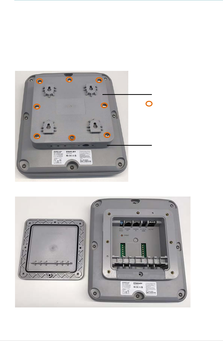
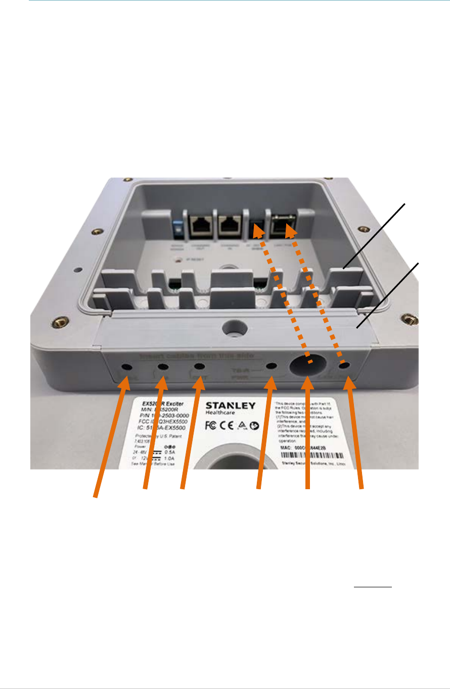
Exciter Connector Panel
The EX5210R Exciter connection panel is housed in the sealed compartment at
the back of the Exciter.
Unscrew the 8 mounting plate screws and remove the plate.
Exciter Mounting Plate
8 Mounting Plate Screws
Sealed Connector Compartment
EX5210R Exciter Installation & Configuration Guide
11
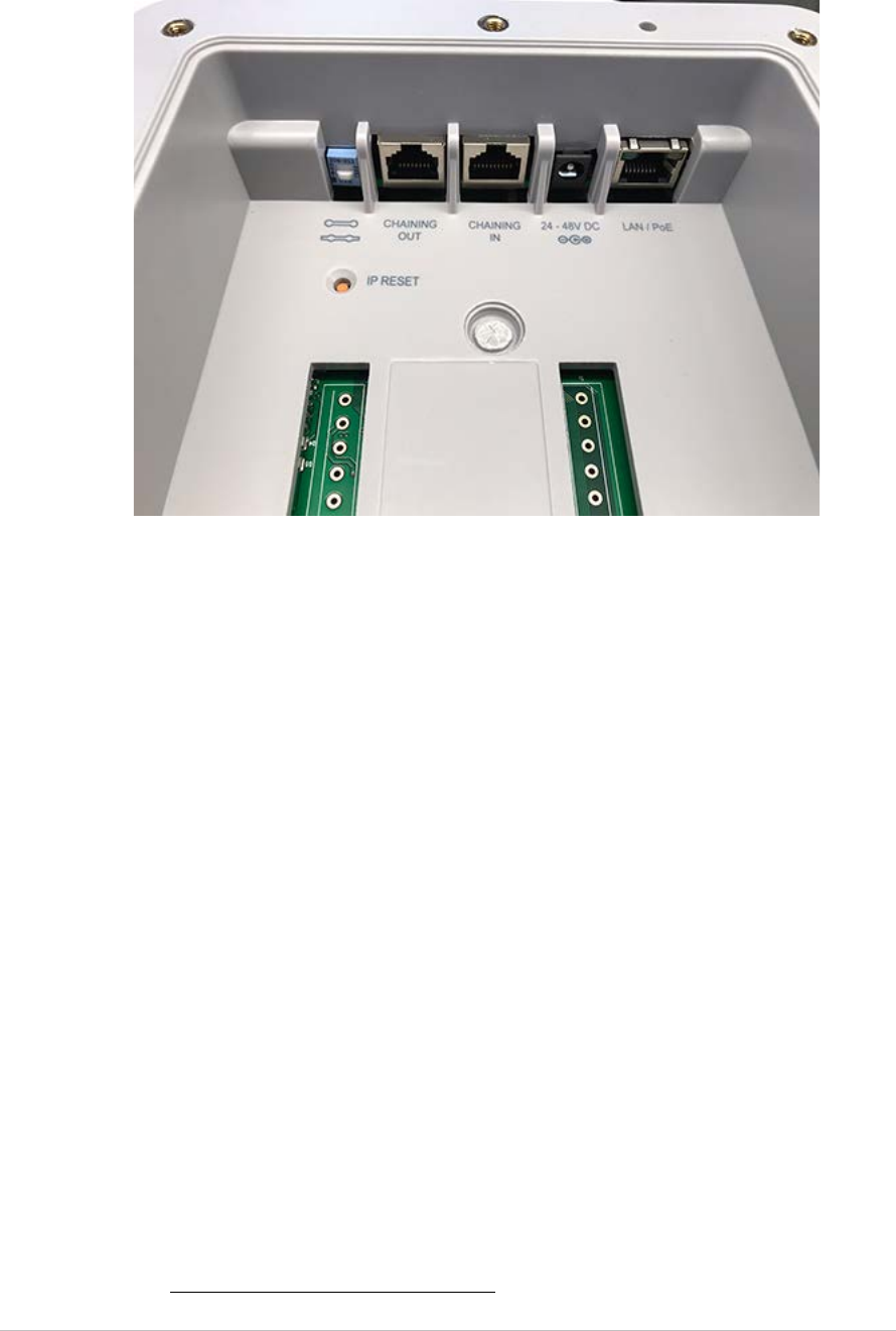
The Exciter has four connectors and two switches inside the back panel:
Figure 3: EX5210R Connector Wiring
(#1) Ethernet LAN Connection: RJ-45 connector. In a configuration with a
physical Ethernet cable connection to the LAN, the network cable is attached
here.
Permanent connection to a wired network is not mandatory. However, you
must have a wired connection to configure the Exciter. Some monitoring
functions are not available if the Exciter is not connected to the network. This
connection is also used for Power over Ethernet (PoE, 802.3af).
(#2) Power Jack: Accepts an input voltage of 24-48V DC. This is a standard 5.5
mm jack connector for direct power supply. The power Adaptor is not supplied
with the Exciter and can be purchased separately. When PoE is used, this
connector becomes redundant.
(#3) Chain IN: RJ-45 connector. This connector is used for receiving data from
Chained Exciters. The Chain IN port is also used to set the Exciter IP via the
Exciter Manager Application using a special 10-pin RJ45 to DB9 serial cable
(AeroScout SKU EXM-1000, or part of the Hardware Management kit).
(#4) Chain OUT and Control Connector: RJ-45 connector. This connector is
used for distributing power and data to Chained Exciters and to connect the
External LF Antenna device. The output voltage is 12 V DC (0.5A maximum).
(#5) Termination Switch: For defining the termination settings in a Chained
Exciters installation. The termination of the first and last Exciter in the chain
must be set to On (o-o) and the other Exciters set to Off: (-o-o-).
(#6) IP Reset: Restores the Exciter’s IP address to the company-set default
value. See Resetting the Exciter IP Address for details.
1
2
3
4
5
6
EX5210R Exciter Installation & Configuration Guide
12
Wiring the Exciter
When wiring the Exciter, all cables must be pushed through the removable
cable rubber plug and then connected to the required port. Use the cable
holder to keep the cables in-line with the rubber’s holes.
Once the cables are connected correctly, place and screw in the mounting panel.
Make sure the mounting panel is secured and sealed correctly before mounting
the Exciter.
Cable Holder
Cable
Rubber Plug
TB-L
IN
OUT
TB-R
PWR
LAN / PoE
EX5210R Exciter Installation & Configuration Guide
13
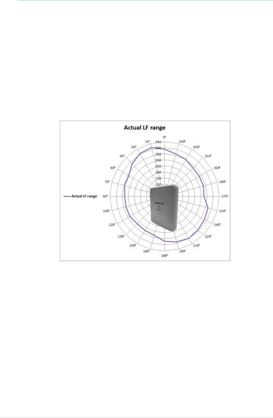
LF Coverage
The EX5210R has an adjustable coverage range between 0.5m (1.6 ft.) and 6.5m
(21.3 ft.) in intervals of 0.5 m (1.6 ft.). LF Coverage varies according to location*
*Indoor LF Coverage is around 6.5 meters (21.3 feet). Outdoor LF Coverage is
around 3 meters (9.8 feet).
The LF coverage pattern set at 4m is displayed in Figure 5.
Figure 4: EX5210R LF range and coverage pattern set at 4m

EX5210R Exciter Installation & Configuration Guide
14
Network and Power Connections
The following is a brief summary of available powering and networking
options:
Usage Option Description
Single EX5210R– not
connected to a
network
EX5210R can be used as standalone device that
functions independently without any network
connection. In this case, you only need to connect the
Exciter to the power supply.
Using the AeroScout Engine Manager (AEM), set the
device as “not connected to the network."
Single EX5210R–
connected to a
network
EX5210R can be remotely controlled (for configuration
and monitoring purposes) via the local area network. In
this case, you need to connect it to both a power source
and the network.
The power can be provided either via the LAN/ PoE
connector, or via the dedicated power supply
connection, using 24-48VDC.
Chained Exciter In case of a Chained Exciter, the Primary Exciter controls
the Chained Exciter over RS485 communication.
An external power supply can be used to power up to
two Exciters. In case external power is used, every
second Exciter needs to be powered (#1 in the chain, #3,
#5, #7).
In case PoE is used (either via a PoE switch or PoE
injector), two EX-5210R can be powered from one PoE
port.
EX5210R Exciter Installation & Configuration Guide
15
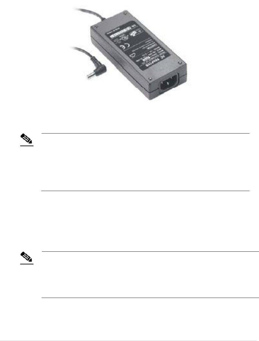
Direct Power Supply
To connect to the power supply, connect a 110/220 VAC to 48 VDC power
Adaptor to the Exciter’s power jack.
Figure 5: 110/220 VAC to 48 VDC Adaptor
Note
The EX5210R requires approximately 6W of power. When connecting an
Exciter to a direct power source, verify that the power level is sufficient.
When using a direct power source for chaining, you can only power up to
two Exciters sequentially, even if the power source is sufficient for more.
Exciters must only be powered by a limited (marked LPS or NEC class 2)
power supply.
PoE Switch
If your network has a Power-over-Ethernet infrastructure, you can connect a
CAT-5/6 Ethernet cable from the PoE switch to the Exciter’s LAN connector. This
supplies both the power and the network connection.
Note
PoE standard 802.3af class 0 allows power for a single EX5210R Exciter.
When using PoE with the other Chained Exciters, a PoE connection must be
made to every second Exciter in the chain. In addition, the LAN connectivity
that the PoE supplies is not used for Chained Exciters in a chain. Chained
Exciters receive data from the Primary Exciter via the Chaining IN connection.
EX5210R Exciter Installation & Configuration Guide
16
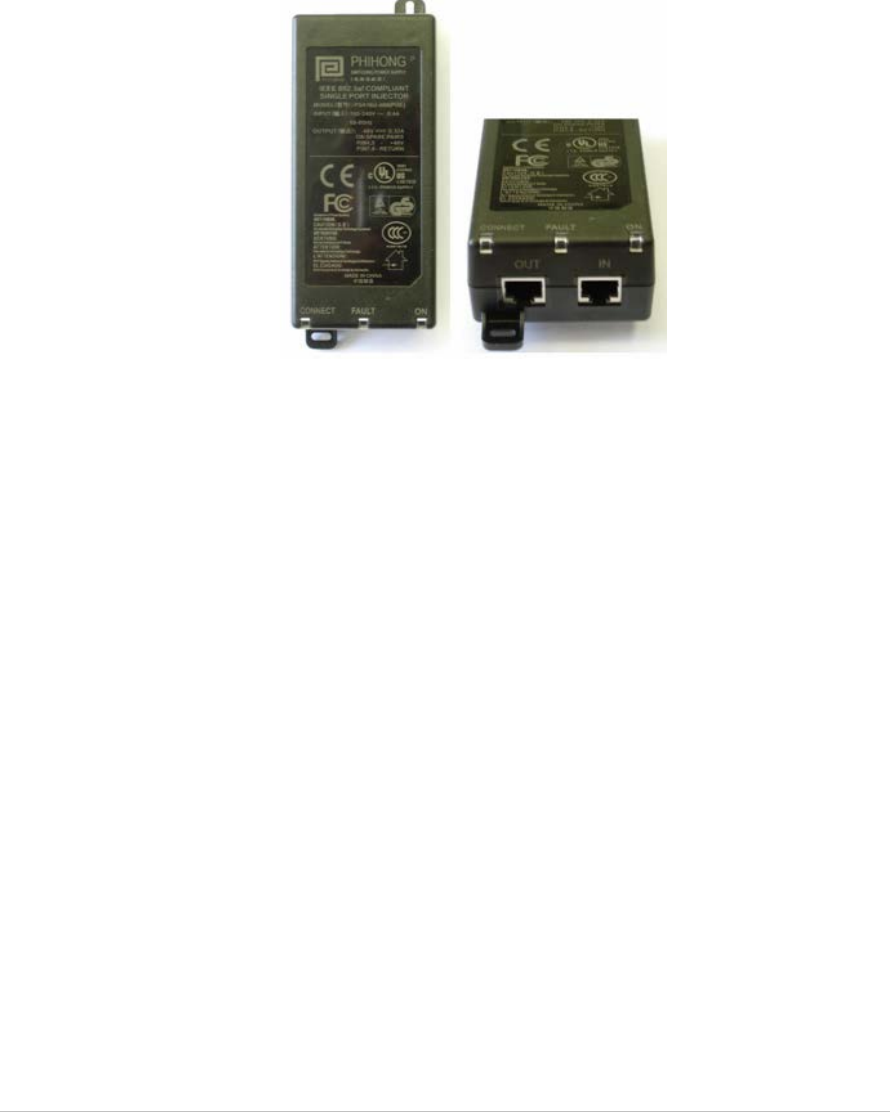
110/220 VAC to 48 VDC PoE Single-Port Injector
The PoE Single Port Injector converts 110/220 VAC to 48 VDC. In addition, it can
receive a network connection and you can run a single cable to the Exciter’s LAN
connector, thus supplying both power and network connectivity.
When using this injector, the Exciter power jack is not used.
Figure 6: 110/220 VAC to 48VDC PoE Single-Port Injector
The injector’s IN connector is connected to the network. The injector’s OUT
connector is connected to the Exciter’s LAN connector.
The injector can be used for both networked and non-networked Exciters. In the
case of a non-networked Exciters, the IN connector on the injector is not used.
EX5210R Exciter Installation & Configuration Guide
17
Power Connection Summary
The following table summarizes the power connection options:
Power Supply Input Output
Maximum
Current
Available
Power
Maximum #
of Exciters
with One
Source
PoE single port
injector
100-240
VAC, 50-
60 Hz
48 VDC 0.32 A(1) 15.4 W Two
Standard PoE 802.3af
switch port(2)
– 48 VDC 0.32 A(1) 15.4 W Two
External power
Adaptor
– 48 VDC > 0.4 A > 20 W Two
Note
To prevent power loss, PoE cables must not exceed 100m (330’) in length.
EX5210R Exciter Installation & Configuration Guide
18
Chaining EX5210R Exciters
In an area where the required LF coverage exceeds the capacity of one Exciter,
you can extend the coverage by chaining several Exciters. For example, a large
entrance with two sets of double doors too wide for a single Exciter might
require two Exciters chained together.
The system treats Chained Exciters as a single device with a single ID.
Transmissions do not interfere with one another.
Each Exciter must be positioned to allow transmission range overlap between
neighboring Exciters. This ensures full coverage of the area.
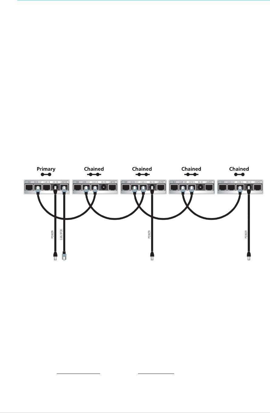
Figure 8 shows 5 Chained Exciters, their connections and the state of each
Exciter termination switch.
Figure 7: EX5210R Chaining Using a Power Adaptor
EX5210R Chain Connection
Up to 8 Exciters can be connected in a chain, as follows:
1. The first Exciter in the chain, directly connected to the LAN, is designated
the “Primary”. Other Exciters are designated “Chained”.
EX5210R Exciters can act as either Primary or Chained Exciters.
2. The Primary Exciter is connected to the first Chained Exciter as follows:
Primary Chaining OUT to Chained Chaining IN.
3. Chained Exciters are then connected as follows: Chaining OUT to Chaining
IN.
EX5210R Exciter Installation & Configuration Guide
19
4. The Termination Switch of the Primary Exciter and the last Chained Exciter
in the chain must be set to On (o-o).
On the other Chained Exciters, it must be set to Off (-o o-).
5. The Primary/Chaining configuration is set via AeroScout Engine Manager.
Chained Exciters inherit the Primary Exciter ID and LF configuration.
Transmission range is configurable. See Configuring Chained Exciters.
Configuring Chained Exciters
Each Chained Exciter must be set as ‘Slave Exciter’ and the transmission range
configured, in the AeroScout Engine Manager, before being connected to the
Primary. The EX5210R appears as an EX5210 in the Engine Manager.
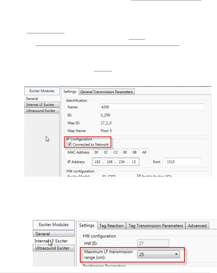
Configurations for Engine 5.2 and below
1. Connect the Chained Exciter directly to the network via the LAN port.
2. Under IP Configuration, check Connected to network.
3. Configure the following parameters:
• Transmission Range (Internal LF Exciter > Settings tab): Select the
desired transmission range of the Chained Exciter so that the LF
coverage is sufficient and some overlap exists between the chained
Exciters.
EX5210R Exciter Installation & Configuration Guide
20
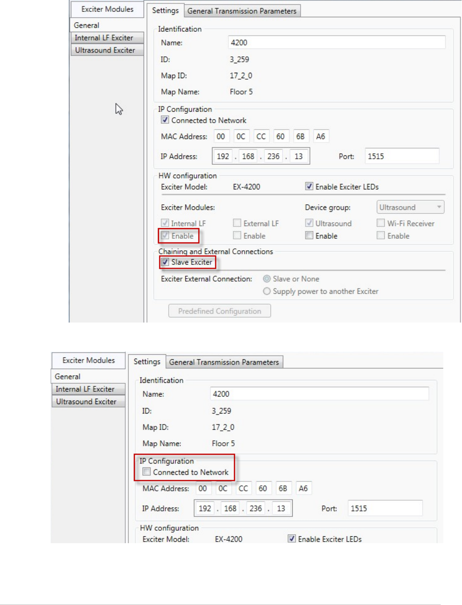
• Under Exciter Modules (General > Settings tab), make sure Enable is
checked.
• Under Chaining and External Connections (General > Settings tab), check
Slave Exciter.
4. Under IP Configuration, uncheck Connected to Network.
5. Click OK.
6. Connect the Chained Exciter to the Primary Exciter.
EX5210R Exciter Installation & Configuration Guide
21
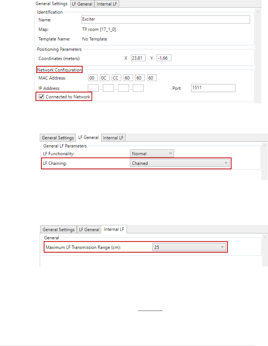
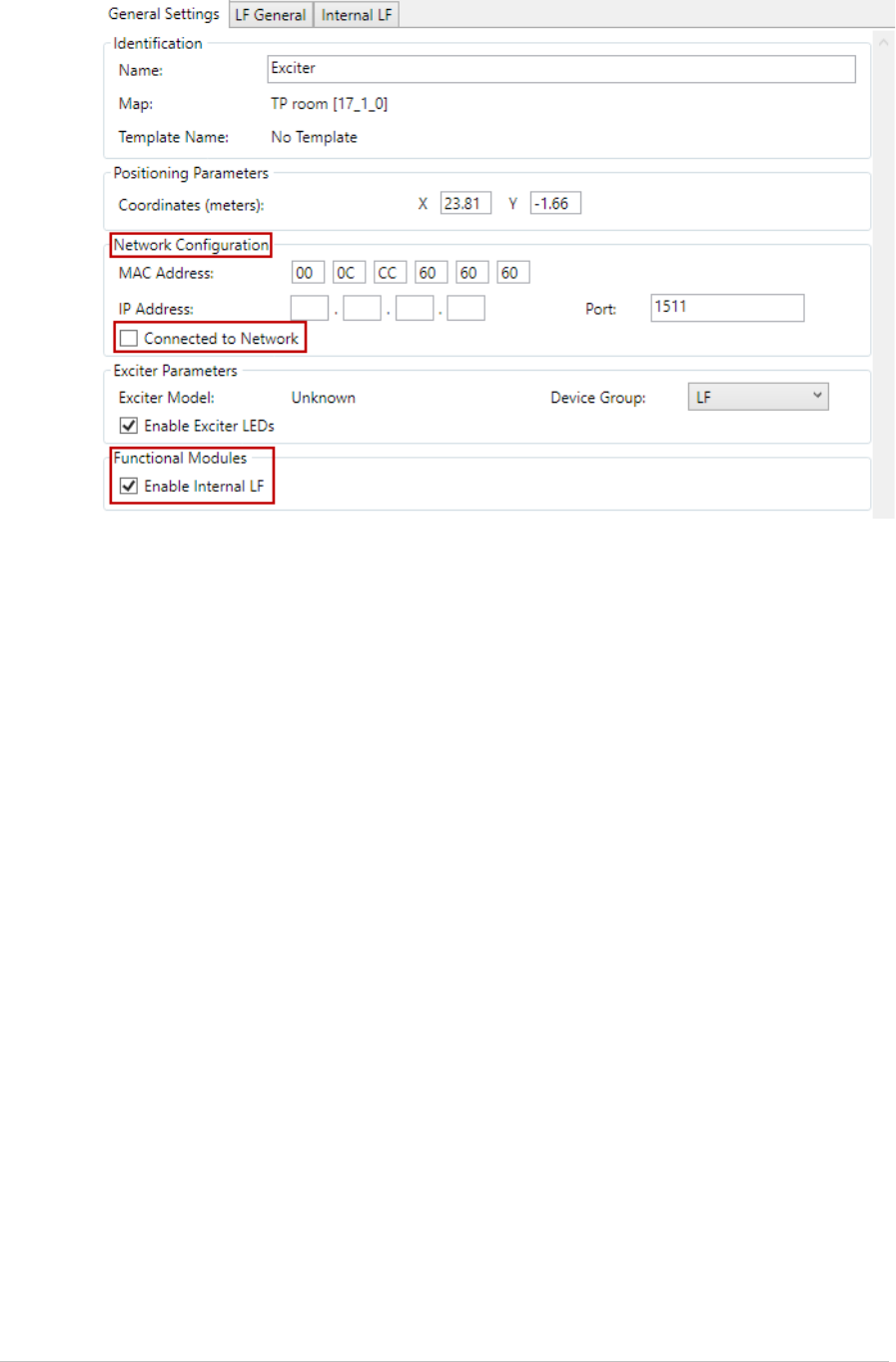
Configurations for Engine 5.3 and above
1. Connect the Chained Exciter directly to the network via the LAN port.
2. In the General Settings tab, under Network Configuration, make sure
Connected to Network is checked.
3. Select the LF General tab and configure the following parameters:
• Under General LF Parameters select LF Chaining as Chained.
4. Select the Internal LF tab and configure the following:
• Select the desired Transmission Range of the Chained Exciter so that
the LF coverage is sufficient and some overlap exists between the
chained Exciters.
5. Select the General Settings tab again and perform the following:
• Under Functional Modules make sure that Enable Internal LF is
checked.
• Under Network Configuration uncheck Connected to Network.
EX5210R Exciter Installation & Configuration Guide
22
6. Click OK.
7. Connect the Chained Exciter to the Primary Exciter.
EX5210R Exciter Installation & Configuration Guide
23
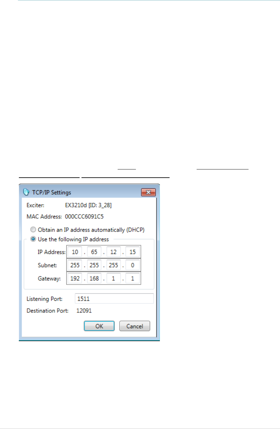
DHCP
Exciters with firmware version 314.54 and above support Dynamic IP (DHCP) and
Static IP configurations.
Static: The IP address and connection settings are specified manually.
Dynamic (DHCP): The DHCP server automatically assigns an available IP every
time the device connects to the network.
Exciters with firmware version 314.54 and above will be set to DHCP by default.
The Exciter’s IP can be changed via the Location Engine; (Select Configuration,
Exciters, IP Settings or right-click an Exciter and select IP Settings. This
command allows you to change the network addressing details of the exciter).
For more information, see the DHCP section in the any Location Engine
Deployment Guide from version 5.1 and above.
EX5210R Exciter Installation & Configuration Guide
24
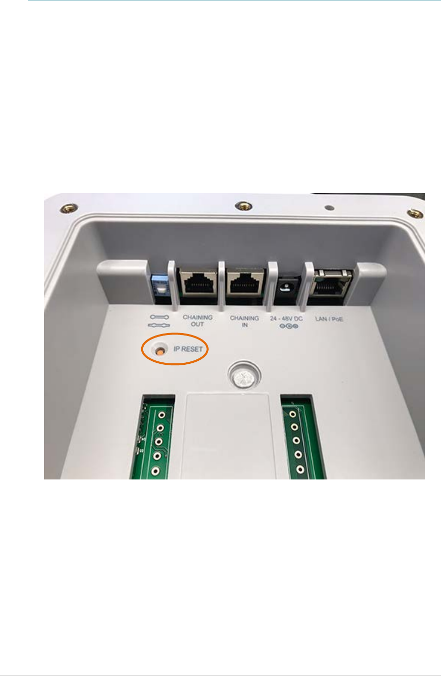
Resetting the Exciter IP Address
You can reset the Exciter’s IP address to the factory default value. The default IP
address is 192.168.1.178.
To do so, press the IP Reset button with a ballpoint pen for 5 seconds.
After a successful IP reset, a flashing red LED indication appears for three
seconds.
Figure 8: IP Reset Button
EX5210R Exciter Installation & Configuration Guide
25
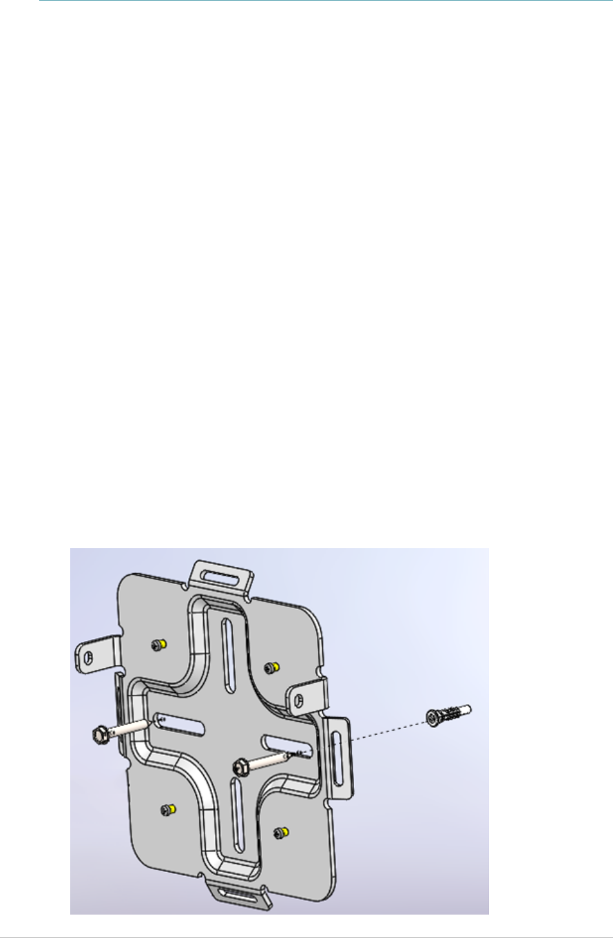
Mounting the Exciter
Position and mount each EX5210R Exciter in the site according to the site survey
recommendations.
The EX5210R Rugged Exciter is designed for outdoor mounting using a
specifically designed mounting plate. Mounting options include:
Walls
Ceilings
Polls
Fixing the Exciter to a Wall/Ceiling
1. Using the mounting plate as a template, place and hold the mounting plate
to a wall or ceiling surface.
2. Mark the screw holes that will be used for mounting.
3. Drill the holes for the screws.
4. Mount the Exciter mounting plate using the correct screws and anchors
required for the mounting surface.
EX5210R Exciter Installation & Configuration Guide
26
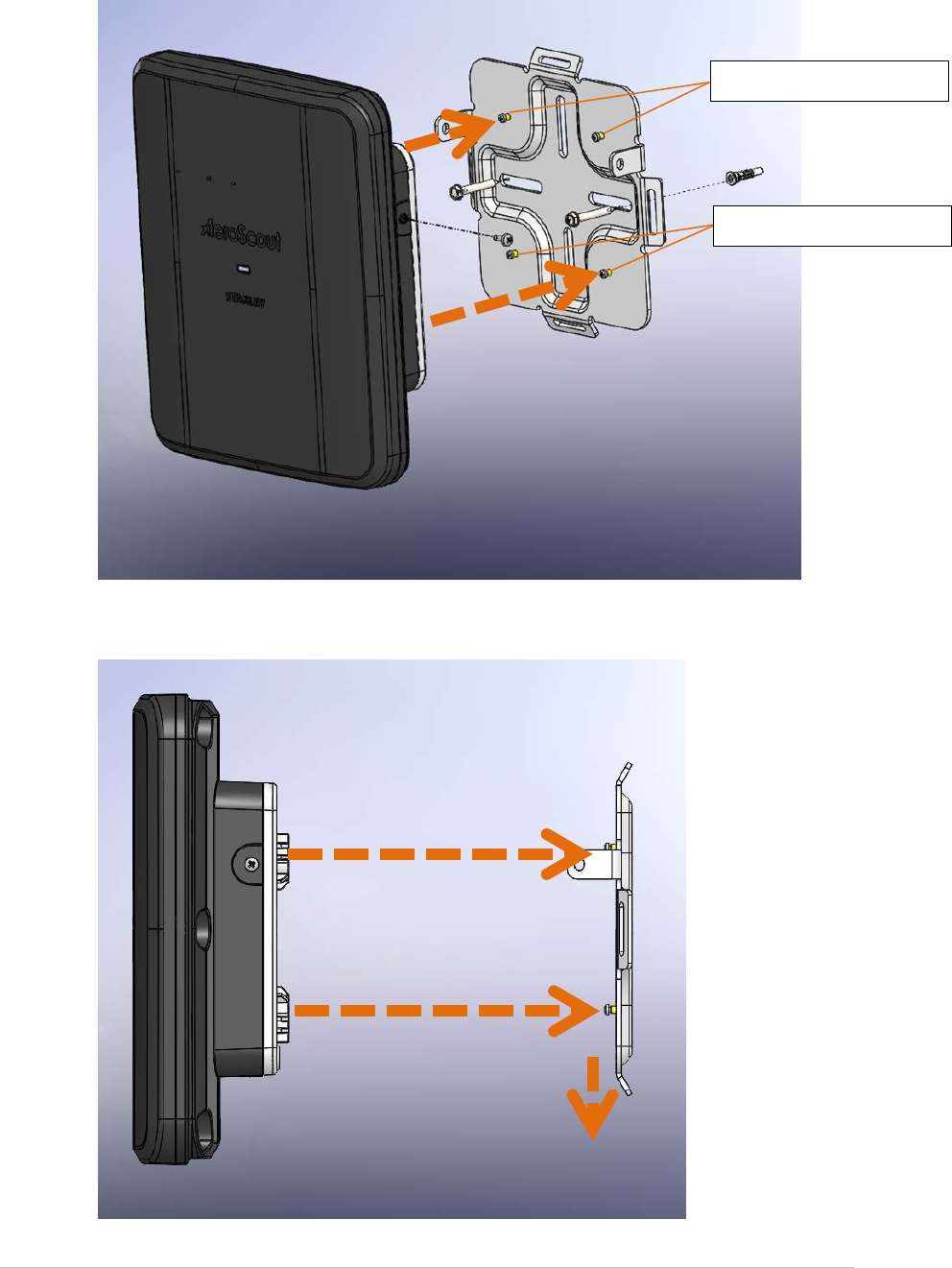
5. Align the Exciter with the attachment hooks on the mounting plate.
6. Place the Exciter into the mounting plate and press the Exciter down until it
locks into place.
Exciter attachment hooks
Exciter attachment hooks
EX5210R Exciter Installation & Configuration Guide
27
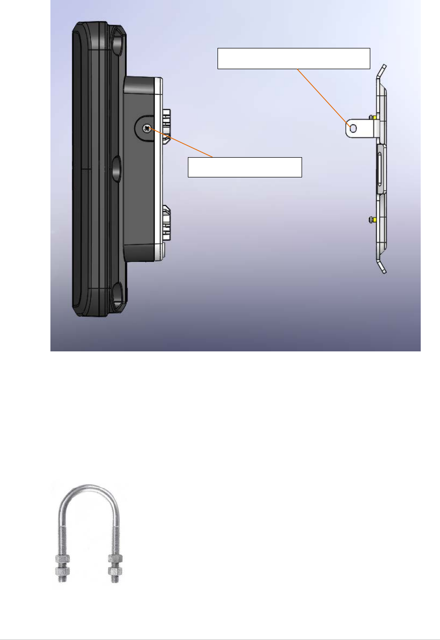
7. When the Exciter is correctly locked into place, the mounting plate’s security
flange will align with the Exciter’s side screw holes.
8. Screw in the Exciter to the mounting plate’s security flanges.
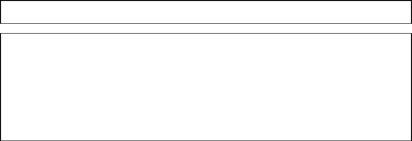
Mounting the Exciter to a Poll
The mounting plate can be mounted to a poll using a U-Bolt mounting kit. Once
the mounting plate is mounted, attach the Exciter and screw it into the
mounting plate’s security flanges.
Mounting plate security flange
Exciter side screw holes

EX5210R Exciter Installation & Configuration Guide
28
Appendix A: Exciter and Accessories
Product SKU Description
EX5210R
Exciter
EX-5210R
M/N: EX-5200R
EX5210R Exciter includes 48 VDC input,
Ethernet and PoE interface. Wall mounting
plate included. Power supply not included.
Exciter
Power
Supply
APD-047-U (US)
APD-047-E (Europe)
APD-047-UK (UK)
APD-047-J (Japan)
AC/DC Adaptor 45W 48 V/1.0A 90-264VAC
for EX2000B, EX4210, EX5000, EX5200 and
EX5210R Exciters.
PoE Injector ADP-030-U (US)
ADP-030-E(Europe)
ADP-030-UK (UK)
ADP-030-J (Japan)
PoE Power Injector for use with EX2000B,
EX3210, EX4210, EX5000, EX5200 and
EX5210R Exciters. 110/220VAC-48VDC.
Exciter
Detector
Tool
EXD-1000 Tool for visualizing the effective LF Exciter
transmission field. Analyzes the Exciter
coverage during deployment. Includes a PC
application and detector hardware that can
be connected via USB to a PC.
U-Bolt
mounting
kit
TBD Used for pole mounting

EX5210R Exciter Installation & Configuration Guide
29
Appendix B: Exciter Specifications
Product Model
SKU: EX-5210R
M/N: EX-5200R
Physical and Mechanical
Dimensions: 232mm X 262mm X 102mm (9.1in x 10.3in x 4in)
Weight: 1.8 kg (4lbs)
Housing: Reinforced Polycarbonate with 10%GF (Lexan 503R from Sabic)
Coverage
Adjustable coverage range between 0.5m (1.6 ft.) and 6.5m (21.3 ft.) by
intervals of 0.5 m (1.6 ft.).
Note the following:
In an outdoor environment, the Exciter’s actual LF coverage range is a maximum
of 3meters (9.8feet), even if it is set to the maximum of 6.5m in the Engine.
When used indoors, the Exciter’s LF coverage range can reach up to 6.5meters.
LF Channel
125 KHz
Field intensity limits: 66dBuV/m @ 10m (ETSI)
Propagation limits: 25.7dBuV/m@ 300m (FCC)
Modulation: ASK
Network Interface
Ethernet (RJ-45)
Power
Input voltage: 24-48 VDC
PoE (802.3af) 48 VDC
Maximum power consumption: 6W
Maximum power consumption of External LF Antenna: 5W
Environmental
Operating temperature: -20°C to 50°C (-4°F to 122°F)
Humidity: 0 to 95%, non-condensing
Ingress Protection Rating: IP-65
Certifications
Radio:
FCC Part 15, sub-part C class B, sub-part B EN 300-330, EN 301-489
RSS 210 (Canada), EMC IEC60601-1-2 (Europe)
Safety:
CE, cTUVus (EN60950)
FCC Compliance Statement
This device has been tested and found to comply with the limits for a Class B digital device,
pursuant to Part 15 of the FCC Rules. These limits are designed to provide reasonable protection
against harmful interference in residential installations. This equipment generates uses and can
radiate radio frequency energy and, if not installed and used in accordance with the instructions,
may cause harmful interference to radio and television reception.
However, there is no guarantee that interference will not occur in a particular installation. If this
device does cause such interference, which can be verified by turning the device off and on, the
user is encouraged to eliminate the interference by one or more of the following measures:
• Re-orient or re-locate the receiving antenna.
• Increase the distance between the device and the receiver.
• Connect the device to an outlet on a circuit different from the one that supplies power to the
receiver.
• Consult the dealer or an experienced radio/TV technician.
WARNING! Changes or modifications to this unit not expressly approved by the party
responsible for compliance could void the user’s authority to operate the equipment.
This device complies with FCC Rules Part 15 and with Industry Canada licence-exempt RSS
standard(s). Operation is subject to two conditions: (1) This device may not cause harmful
interference, and (2) this device must accept any interference that may be received or that may
cause undesired operation.
Le present appareil est conforme aux CNR d'Industrie Canada applicables aux appareils radio
exempts de licence. L'exploitation est autorisee aux deux conditions suivantes :(1) l'appareil ne
doit pas produire de brouillage, et (2) l'utilisateur de l'appareil doit accepter tout brouillage
radioelectrique subi, meme si le brouillage est susceptible d'en compromettre le
fonctionnement.

About STANLEY Healthcare
STANLEY Healthcare provides over 5,000 acute care hospitals and 12,000 long-term care organizations
with enterprise solutions that create a safe, secure and efficient healthcare experience across life’s
stages. The STANLEY Healthcare solution set enables customers to achieve organizational excellence
and superior care in critical areas: Patient/Resident Safety, Security & Protection, Environmental
Monitoring, Clinical Operations & Workflow and Supply Chain & Asset Management. These solutions
are complemented by STANLEY Healthcare’s By Your Side™ Lifetime Customer Care commitment to
ensure that every customer achieves success and realizes the full value of their investment, through
consulting, training, implementation and integration services. STANLEY Healthcare is proud to be part
of Stanley Black & Decker, Inc. For more information, visit stanleyhealthcare.com. Follow STANLEY
Healthcare on Facebook, Twitter, LinkedIn and YouTube.
STANLEY Healthcare
130 Turner Street
Building 3
Waltham, MA 02453
Tel: +1-888-622-6992
North America
E-mail: stanleyhealthcare@sbdinc.com
Asia-Pacific
E-mail: stanleyhealthcare-asiapac@sbdinc.com
Europe
E-mail: shs-uk@sbdinc.com
Latin America
E-mail: stanleyhealthcare-latam@sbdinc.com
Middle East
E-mail: stanleyhealthcare-MEA@sbdinc.com