AeroScout EX5500 AeroScout LF Exciter with Internal Wi-Fi Receiver User Manual Tag Manager Professional Edition
AeroScout AeroScout LF Exciter with Internal Wi-Fi Receiver Tag Manager Professional Edition
USERS MANUAL

EX5500 Controller
Installation & Configuration Guide
0981-029 Rev A
Disclaimer
The information and know-how included in this document are the exclusive property of Stanley
Healthcare. and are intended for the use of the addressee or the user alone. The addressees shall not
forward to another their right of using the information, know-how or document forwarded herewith, in
whole or in part in all matters relating or stemming from or involved therein, whether for
consideration or without consideration, and shall not permit any third party to utilize the information,
know-how or the documents forwarded herewith or copies or duplicates thereof, unless at the
company’s consent in advance and in writing. Any distribution, advertisement, copying or duplication
in any form whatsoever is absolutely prohibited. The Company reserves the right to sue the
addressee, user and/or any one on their behalves, as well as third parties, in respect to breaching its
rights pertaining to the intellectual rights in particular and its rights of whatever kind or type in the
information, know-how or the documents forwarded by them herewith in general, whether by act or
by omission.
This document is confidential and proprietary to Stanley Healthcare and is not to be distributed to any
persons other than licensed AeroScout Visibility System users or other persons appointed in writing
by Stanley Healthcare.
Trademark Acknowledgements
AeroScout is a trademark of Stanley Black & Decker. Other brand products and service names are
trademarks or registered trademarks of their respective holders. Below is a partial listing of other
trademarks or registered trademarks referenced herein:
Cisco™ is a trademark of Cisco Systems, Inc.
Sun, Sun Microsystems, the Sun Logo, Java, JRE and all other Sun trademarks, logos, product names,
service names, program names and slogans that are referred to or displayed in this document are
trademarks or registered trademarks of Sun Microsystems, Inc. in the United States and other
countries.
This product includes software developed by the Apache Software Foundation
(http://www.apache.org/).
This product includes code licensed from RSA Data Security
Skype, SkypeIn, SkypeOut, Skype Me, the Skype Logo and the S logo and other marks indicated on
Skype’s website are trademarks of Skype Limited or other related companies.
ESper is a trademark of EsperTech, Inc.
Jboss is a trademark of Red Hat Middleware, LLC.
Oracle 10G is a registered trademark of Oracle Corporation and/or its affiliates.
MS SQL Server 2005 is a registered trademark of Microsoft Corporation in the United States and/or
other countries.
JasperSoft, the JasperSoft Logo, JasperReports, the JasperReports logo, JasperIntelligence,
JasperDecisions, JasperAnalysis, Scope Center, Scope Designer, and JasperServer are trademarks or
registered trademarks of JasperSoft, Inc. in the United States and other countries.
2013 Stanley Healthcare. All rights reserved.

Table of Contents 3
Table of Contents
Introduction ......................................................................................................................... 4
EX5500 Controller Applications and Industry Examples ............................................. 5
EX5500 Controller Features ............................................................................................... 6
EX5500 LED Status Indicators .......................................................................................... 7
Network and Power Connections to EX5500 ............................................................... 10
Chaining the EX5500 Controllers ................................................................................... 13
Resetting the EX5500 Controller IP Address ................................................................ 15
Configuring the EX5500 Controller ............................................................................... 16
Configuring the Controller via Cisco MSE ................................................................... 22
Mounting the Controller and External LF Antenna .................................................... 24
Mounting the Controller or External LF using the Exciter Mounting Clip .............. 25
EX5500 and Accessories Model Numbers ..................................................................... 27
EX5500 Specifications ....................................................................................................... 28
EX5500 Controller Installation & Configuration Guide
4
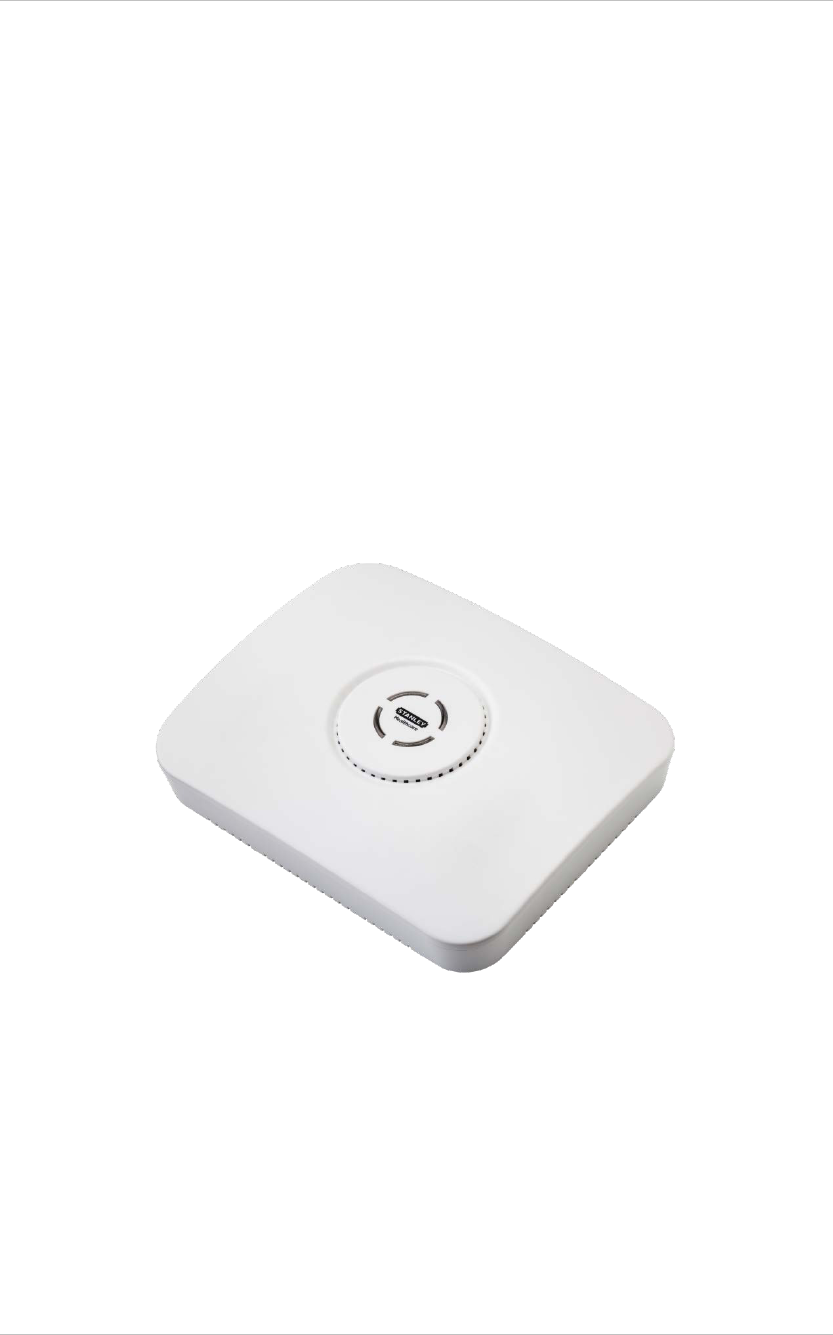
Introduction
The EX5500 Controller is a component of the Stanley Healthcare suite of enterprise-
level visibility solutions based on standard Wi-Fi communication for security and
safety applications. The EX5500 Controller provides sophisticated RFID detection,
monitoring, and control capabilities.
The EX5500 Controller triggers Hugs Tags as they pass through an Egress or as they
approach the Controller. Tags in turn transmit a message to either the Location
Receivers or to compatible Access Points within range. The Controller can activate or
deactivate Tags, program them, or even instruct Tags to operate in a specific way
(for example, to blink). This provides instant acknowledgment that a tagged asset
has passed through a gate, doorway, or other specifically defined area.
Figure 1: Stanley Healthcare EX5500 Controller

EX5500 Controller Installation & Configuration Guide
5
EX5500 Controller Applications and Industry
Examples
Theft Prevention
Healthcare organizations or enterprises with expensive and mission-critical
equipment can tag valuable assets that are intended to remain within a specified
area. The Stanley Healthcare System can track the location of such items and trigger
an alert when they pass through an exit point or enter a restricted area.
Automatic Inventory Management
Logistics organizations can update inventory records by automatically determining
assets within defined areas, ensuring real-time knowledge of inventory levels
without manual checks or barcode scanning.
Real-Time Alerts
Organizations can use Stanley Healthcare Controllers to trigger automated events
and alerts based on the current location of an asset. For example, in a shipping yard,
notifications can be sent when vehicles pass through gates and enter or exit a certain
dock or bonded area.
Security applications
Stanley Healthcare Controllers can be installed at the entrances of restricted areas to
trigger alerts when unauthorized persons attempt to enter or leave. In hospitals,
Controllers can notify staff regarding patient movement, such as a patient leaving
the behavioral health department, or an infant being moved out of the NICU.
Mission Critical Applications
The EX5500 Controller can work in an off-line mode, enabling it to function as a
security application even when the network is down and communication with
MobileView is lost.
EX5500 Controller Installation & Configuration Guide
6
EX5500 Controller Features
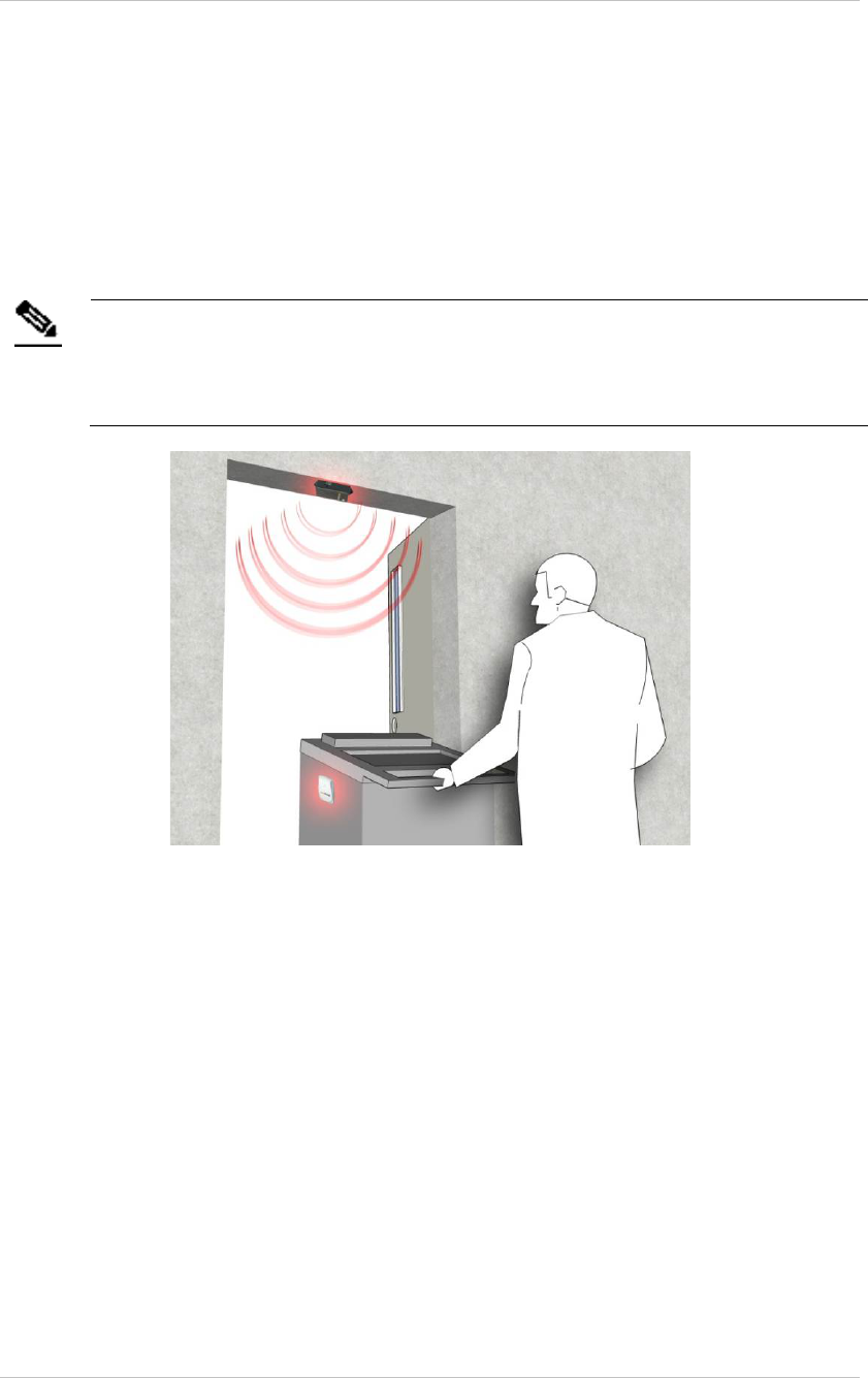
RFID detection of Stanley Healthcare Tags
The EX5500 Controller triggers Tags to transmit as they pass through a defined area,
within a range of up to 6.5 meters (21.3 feet). This is typically enough to cover door
or gate areas. The EX5500 also supports a chained configuration, thus enabling an
increased RFID detection range for larger areas.
Note
The EX5500 Controller’s effective range may be less than the configured
range due to specific site or environmental constraints. The effective
range must be taken into consideration when planning and designing
the deployment.
Figure 2: EX5500 Positioned at a Doorway Triggering a Tag
Tag behavior modification:
The EX5500 Controller can wirelessly activate and deactivate Tags. Tag battery life
can be extended by switching them off when they leave a defined tracking area
through a gate or doorway. The Controller can also be configured to change the Tag
transmission rate temporarily to accommodate different usage patterns in different
environments.
Message Programming functions
The EX5500 Controller can store messages on the Tag for subsequent transmission.
The message transmission can subsequently be triggered by other EX5500s, enabling
sophisticated process control functions.
The EX5500 Controller can trigger a Tag to:
• Transmit up to 15 bytes of data sent to it by the EX5500
EX5500 Controller Installation & Configuration Guide
7
• Transmit one of 15 pre-stored messages
• Store up to 15 bytes of data sent to it by the EX5500
Network connectivity
The EX5500 Controller enables remote programming, monitoring, and software
updates by the Location Engine. In addition, the EX5500 can work in an offline
mode, thus eliminating the need for a physical network connection. In the offline
mode however, remote configuration and monitoring is not available.
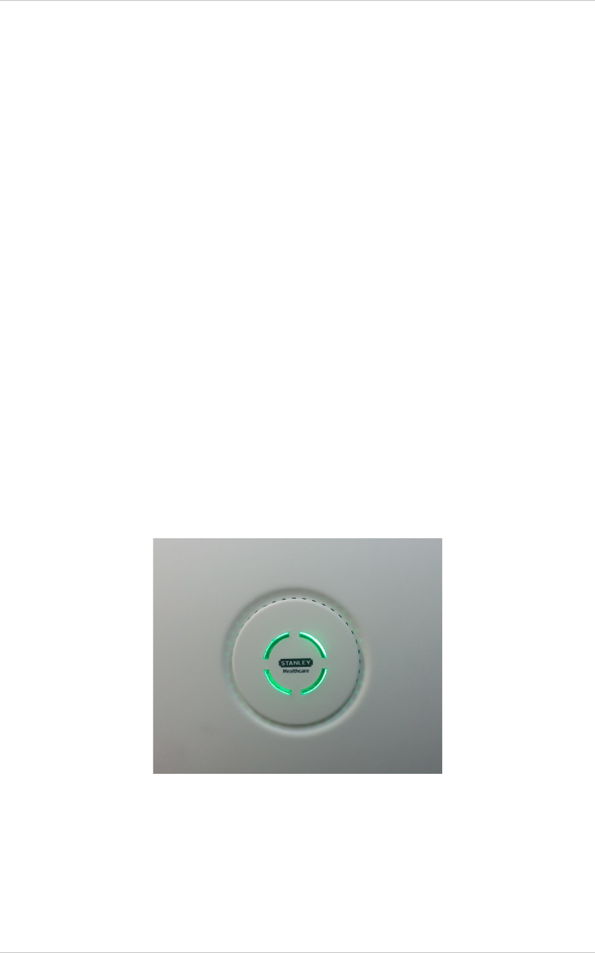
EX5500 LED Status Indicators
The EX5500 has a single LED that changes color based on the Controller status as
follows:
• Constant Green: The Controller is on and working correctly.
• Blinking Green: The Controller is offline.
• Constant Orange: The Controller is being bypassed, for example by a
keypad operation.
• Constant Red: Controller failure or network down.
• No LED indication: Controller is off.
Figure 3: EX5500 LED Indicator
EX5500 Controller Installation & Configuration Guide
8
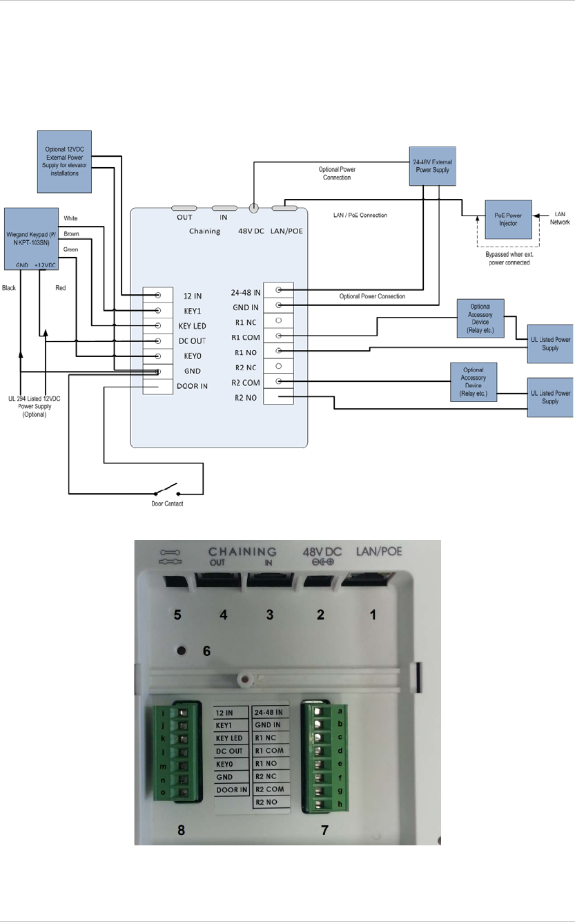
EX5500 Controller Connector Panel
The EX5500 Controller has five connectors and two relay switches on the connector
panel.
Figure 4: Stanley Healthcare EX5500 Connector Wiring
Figure 5: Stanley Healthcare EX5500 Connectors

EX5500 Controller Installation & Configuration Guide
9
(#1) Ethernet LAN Connection: RJ-45 connector. In a configuration with a physical
Ethernet cable connection to the LAN, the network cable is attached here.
Permanent connection to a wired network is not mandatory. However, you must
have a wired connection to configure the EX5500 Controller. Some monitoring
functions are not available if the Controller is not wired. This connection is also used
for Power over Ethernet (PoE, 802.3af).
(#2) Power Jack: Accepts an input voltage of 24-48V DC. This is a standard 2.5 mm
jack connector for direct power supply. The power adaptor is not supplied with the
Controller and can be purchased separately. When PoE is used, this connector
becomes redundant.
(#3) Chain IN/RS-232 Connector): RJ-45 connector. This connector is used for
receiving power and data from chained Controllers. RS-232 is used as a console
interface with the Exciter Manager Application (to change IP for example). For this
option you need a special 10-pin RJ45 to DB9 serial cable (AeroScout PN
40031500000)
(#4) Chain OUT and Control Connector: RJ-45 connector. This connector is used for
distributing power and data to chained Exciters and to connect the External LF
Antenna device. The output voltage is 12 V DC (0.5A maximum).
(#5) Termination Switch: For defining the termination settings in a chained Exciters
installation. The default factory setting is Termination On (o-o). In a chained Exciters
installation, the termination of the first and last Exciter in the chain must be set to On
(o-o) and the other Exciters set to Off (-o-o-).
(#6) IP Reset: Restores the Controller's IP address to the company-set default value.
(#7) Relay Switch: Keypad Relay.
− (#a) 24-48 IN: Power connection accepts 24-48 V Direct Current
− (#b) GND IN: Ground/Earth
− (#c) R1 NC: Relay 1 normally closed connection
− (#d) R1 COM: Relay 1 common connection, always connect
− (#e) R1 NO: Relay 1 normally open connection
− (#f) R2 NC: Relay 2 normally closed connection
− (#g) R2 COM: Relay 2 common connection, always connect
− (#h) R2 NO: Relay 2 normally open connection
(#8) Relay Switch: Device Relay

EX5500 Controller Installation & Configuration Guide
10
− (#i) 12 IN: Power connection accepts 12V Direct Current
− (#j) KEY1: Weigand Keypad connection
− (#k) KEY LED: Connects to Keypad LED
− (#l) DC OUT: Direct Current Power out
− (#m) KEY0: Weigand Keypad connection
− (#n) GND: Ground/Earth
− (#o) DOOR IN: Door switch connection
Note
Connect to COM and NO if you want the switched circuit to be on when
the relay is on.
Connect to COM and NC if you want the switched circuit to be on when
the relay is off.
Network and Power Connections to EX5500
The following is a brief summary of available powering and networking options:
Usage Option Description
Single EX5500 – not
connected to a
network
EX5500s can be used as standalone devices that function
independently without any network connection. In this
case, you only need to connect the EX5500 to the power
supply.
Using System Manager, set the device as “not connected to
the network."
Single EX5500 –
connected to a
network
EX5500s can be remotely controlled (for configuration and
monitoring purposes) via the local area network. In this
case, you need to connect it to both a power source and the
network.
EX5500s also support power-over-Ethernet (PoE), which
supplies both power and network services via a single
connection.
EX5500 Controller Installation & Configuration Guide
11
Direct Power Supply
Connect a 48 VDC power source direct to the Controller’s power jack.
Note
The EX5500 Controller requires approximately 8 W of power. When
connecting a Controller to a direct power source with one of the above
options, verify that the power level is sufficient.
When using a direct power source for chained Exciters, you can only
power up to two Exciters sequentially, even if the power source is
sufficient for more.
Exciters must only be powered by a limited (marked LPS or NEC class
2) power supply.
PoE Switch
If your network has a Power-over-Ethernet infrastructure, you can connect a CAT-5
Ethernet cable from the PoE switch to the Controller’s LAN connector. This supplies
both the power and the network connection.
Note
PoE standard 802.3af class 0 allows power for a single EX5500
Controller
When using PoE with the other chained Exciters, a PoE connection must
be made to every second Exciter in the chain. In addition, the LAN
connectivity that the PoE supplies is not used for slave Exciters in a
chain. Slave Exciters receive data from the Master Exciter via the Chain
IN connection.
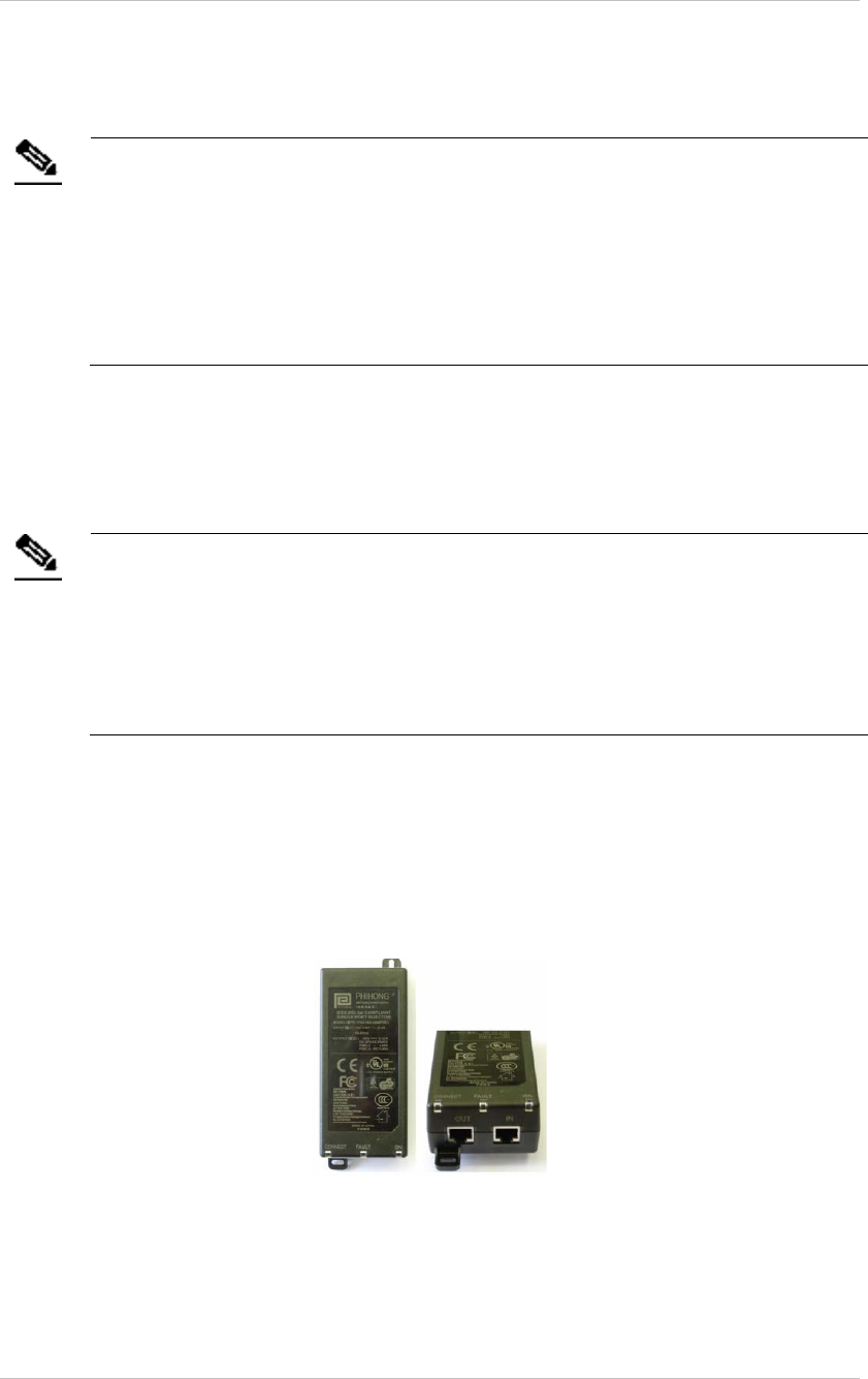
110/220 VAC to 48 VDC PoE Single-Port Injector
The PoE Single Port Injector converts 110/220 VAC to 48 VDC. In addition, it can
receive a network connection and you can run a single cable to the Controller’s LAN
connector, thus supplying both power and network connectivity.
When using this injector, the Controller power jack is not used.
Figure 6: 110/220 VAC to 48VDC PoE Single-Port Injector
The injector’s IN connector is connected to the network. The injector’s OUT
connector is connected to the Controller’s LAN connector.

EX5500 Controller Installation & Configuration Guide
12
The injector can be used for both networked and non-networked Controllers. In the
case of a non-networked Controller, the IN connector on the injector is not used.
110/220 VAC to 48 VDC Power Supply Adaptors
These adaptors convert 110 VAC or 220 VAC to 48 VDC.
Figure 7: 110/220 VAC to 48 VDC Adaptor
The adaptor is connected to the EX5500 Controller’s power jack. The network must
be connected separately to the EX5500 Controller’s LAN connector. This adaptor is
most commonly used for chained Exciters. It can power up to two Exciters.
Power Connection Summary
The following table summarizes the power connection options:
Power
Supply Input Output Max.
Current Available
Power Maximum # of
Exciters with
One Source
PoE single
port injector
100-240
VAC, 50-60
Hz
48 VDC 0.32 A(1) 15.4 W 2
Standard PoE
802.3af switch
port(2)
– 48 VDC 0.32 A(1) 15.4 W 1 EX5500
Controller or 2
other types of
Exciter
External
power source
– 48 VDC > 1 A > 48 W 2
Note
To prevent power loss, PoE cables must not exceed 100m (330’) in
length.
EX5500 Controller Installation & Configuration Guide
13
Chaining the EX5500 Controllers
In an area where the required LF coverage exceeds the capacity of one EX5500
Controller, you can extend the coverage by chaining several Exciters. For example, a
large entrance with two sets of double doors too wide for a single Exciter, might
require two Exciters chained together. EX5000, EX3210, EX2000B or EX4200 Exciters
can be chained to an EX5500 Controller.
Note
EX5500 Controllers cannot be chained to other EX5500 Controllers.
The system treats chained Exciters as a single device with a single ID. Transmissions
do not interfere with one another.
Each Exciter must be positioned to allow transmission range overlap between
neighboring Exciters. This ensures full coverage of the area.
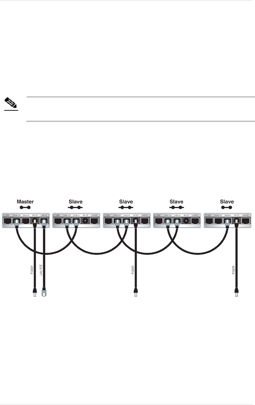
Figure 7 shows 5 chained Exciters, their connections and the state of each Exciter
termination switch.
Figure 8: EX5500 Chaining Using a Power Adaptor
EX5500 Chain Connection
Up to 4 Exciters can be connected to the EX5500 in a chain, as follows:
1. The first Exciter in the chain, directly connected to the LAN, is designated the
“Master”. Other Exciters are designated “Slave”.
EX5500 Controllers can act as either Master or Slave Exciters.
EX5500 Controller Installation & Configuration Guide
14
2. The Master Exciter is connected to the first Slave Exciter as follows: Master
Chain OUT to Slave Chain IN.
3. Slave Exciters are then connected as follows: Slave OUT to Slave IN.
4. The Termination Switch of the Master Exciter and the last Slave Exciter in the
chain must be set to On (o-o).
On the other Slave Exciters, it must be set to Off (-o o-).
5. The Master/Slave configuration is set via System Manager.
Slave Exciters inherit the Master Exciter ID and LF configuration, as well as the
transmission range.
EX5500 Controller Installation & Configuration Guide
15
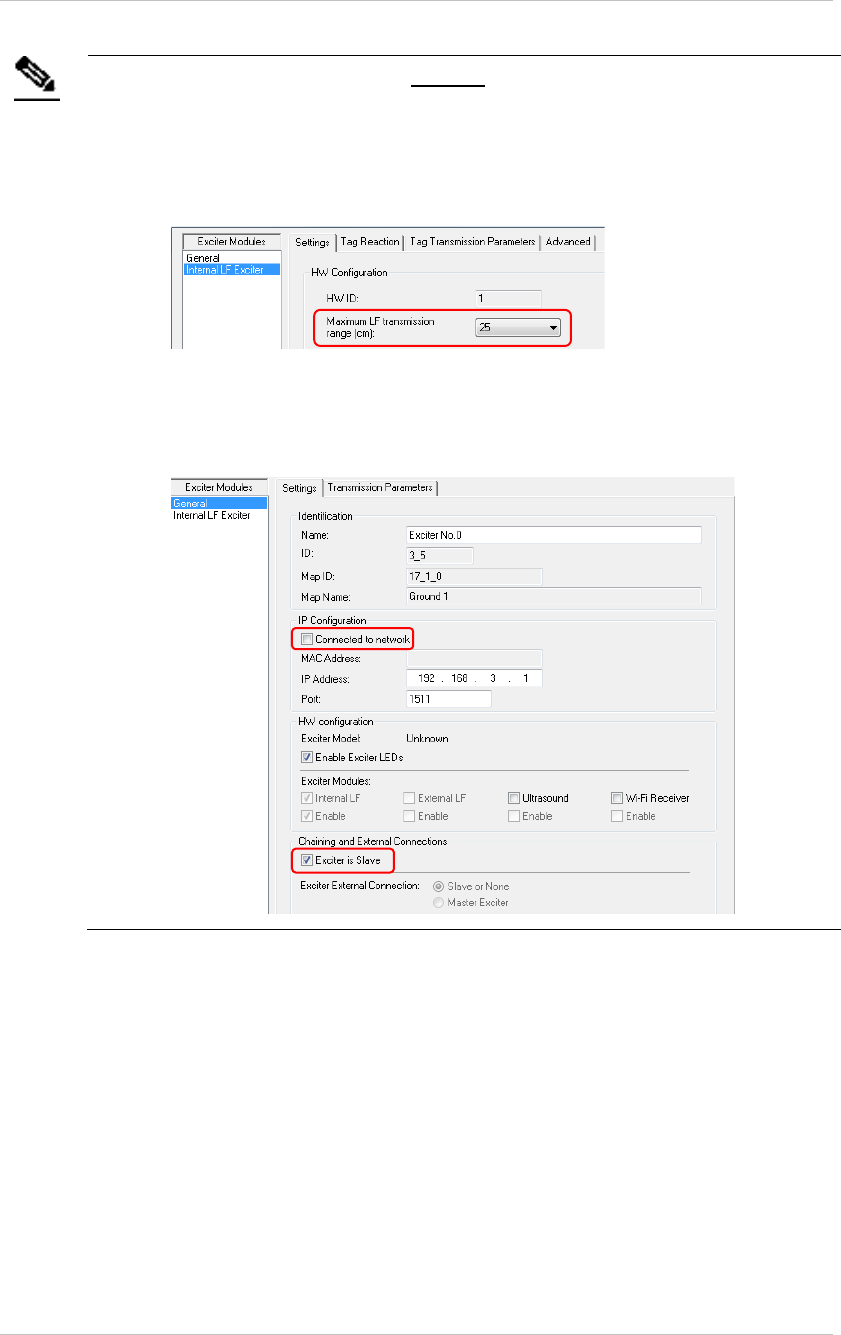
Note
Each slave must be connected directly to the network and configured
the following parameters configured before being connected to the
MASTER:
• Transmission Range: Select the desired transmission range of
the slave Exciter so that the LF coverage is sufficient and some
overlap exists between the chained Exciters' LF coverage
• Connected to network: Make sure the Connected to network
checkbox is unchecked.
• Chaining and External Connections: Check the Exciter is Slave
Checkbox
Resetting the EX5500 Controller IP Address
You can reset the EX5500 Controller’s IP address to the factory default value. The
default IP address is 192.168.1.178.
• Press the IP Reset button with a ballpoint pen for 5 second.
After a successful IP reset, a red LED indication appears for two seconds.
EX5500 Controller Installation & Configuration Guide
16
Configuring the EX5500 Controller
EX5500 Controllers are configured using AeroScout System Manager or Cisco MSE.
The configuration settings consist of device installation and network definitions.
Configuring the EX5500 Controller via System Manager
The EX5500 Controller requires settings in the System Parameters and the Exciter
Properties dialog boxes to be configured. System Manager can automatically detect
the Exciter Model. Once detected a number of settings are automatically configured
by System Manager.
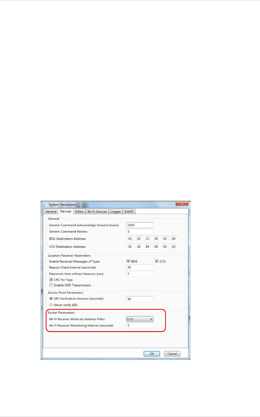
System Parameters
1. Select Configuration, System parameters. The System Parameter dialog box
opens.
2. Select the Devices tab.
a. Set the Wi-Fi Receiver Multicast Address Filter.
b. Set the Wi-Fi Receiver Monitoring Interval.
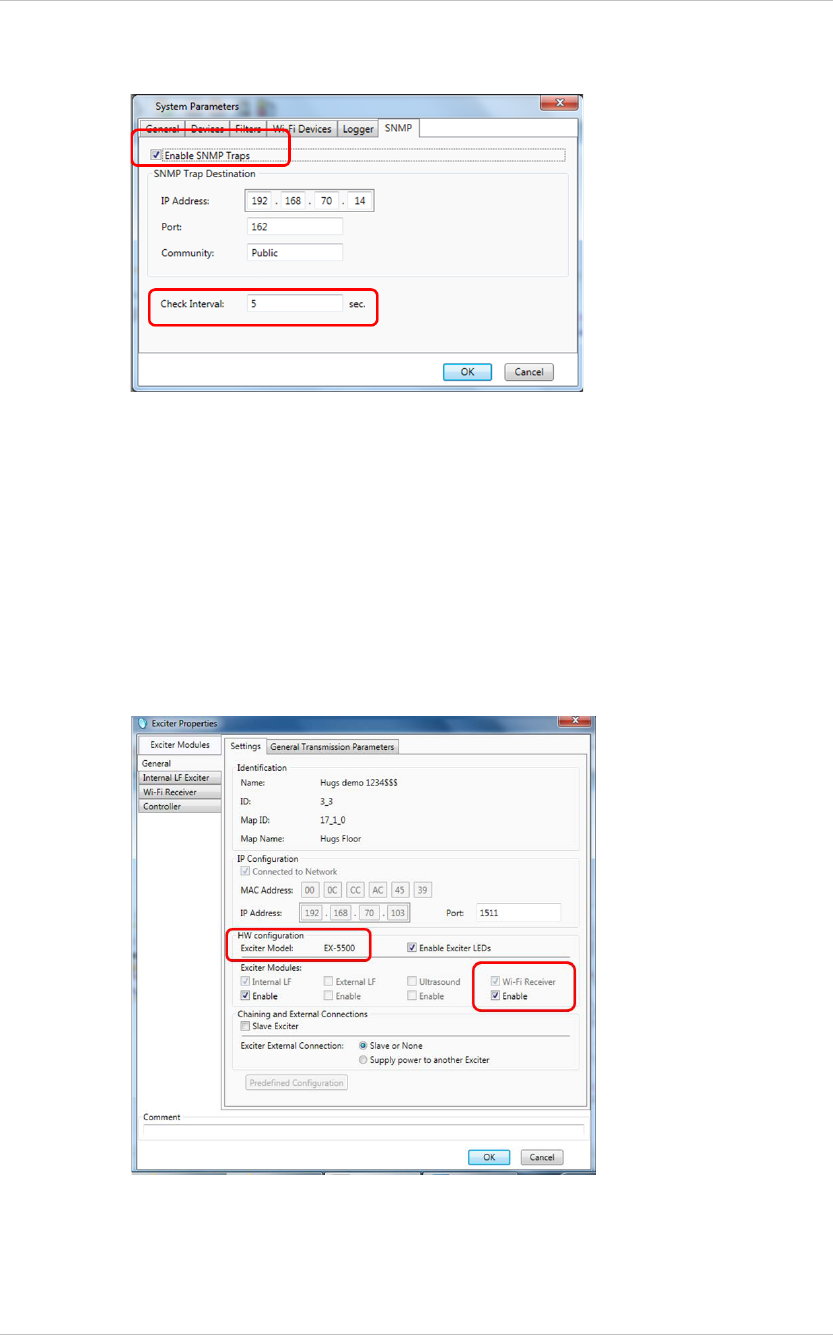
3. Select the SNMP Tab.
a. Check the Enable SNMP Traps checkbox.
b. Set the MobileView IP Address.
EX5500 Controller Installation & Configuration Guide
17
c. Set the Check Interval.
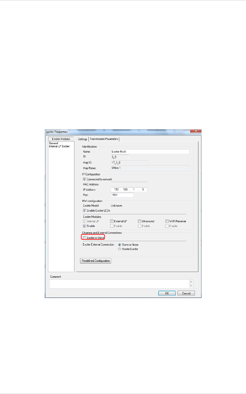
Exciter Properties
1. Add the EX5500 Controller to System Manager.
2. On the map double-click the EX5500 Controller. The Exciter Properties dialog
box opens.
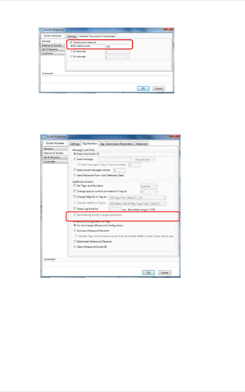
3. In the Exciter Properties dialog box General Module select the Settings tab.
a. Enable the Internal LF Exciter.
b. Select and Enable the Wi-Fi Receiver. Selecting and Enabling the Wi-Fi
Receiver Module adds the Controller module in the Exciter Modules pane.
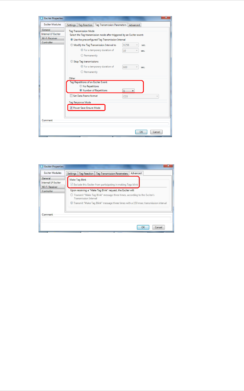
c. Select the General Transmission Parameters tab.
d. Set the LF Transmission Interval to 200 milliseconds.
EX5500 Controller Installation & Configuration Guide
18
4. Select the Internal LF Exciter Module.
a. Select the Tag Reactions tab.
b. Ensure the Send leaving Exciters range notification option is unavailable.
c. Select the Tag Transmission Parameters tab.
d. Tag Repetitions of an Exciter, select the Number of Repetitions option.
e. Set the Number of Repetitions to 3.
EX5500 Controller Installation & Configuration Guide
19
f. Select the Advanced Tab
g. Ensure the Make Tag Blink option is set to Exclude …
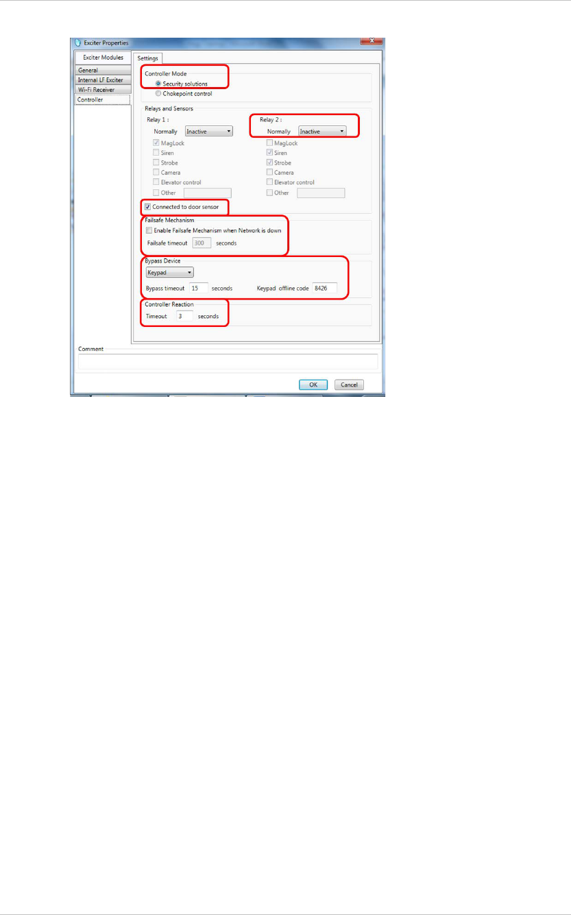
5. Select the Controller Module.
Configure as follows:
EX5500 Controller Installation & Configuration Guide
20
Controller Mode
a. Select Security solutions for Hugs tags only. Select Chokepoint control for
other deployments.
Relays and Sensors
a. Select the Normally state of Relay 1 and Relay 2 as either Active or Inactive.
If a relay is connected to a door Maglock, the normally active relay
configuration would match the door that is normally locked.
b. For the Active and Inactive Relay(s) select the trigger response(s) required, by
checking the corresponding trigger device box.
c. Check the box Connected to door Sensor as required. (The Exciter sends
SNMP traps to MobileView when the door is open and closed)
Failsafe Mechanism
a. Select the Enable failsafe… option to allow the Exciter to monitor the network
status.
b. Enter a time lapse period in seconds, in the Failsafe Timeout field.
If a network connection is not registered within this period the failsafe
mechanism is triggered and the connected trigger device is disabled.
Bypass Device
An override option exists on secure doors. In the event of system activation the
timeout function disables the override function for a specified time.
a. Select the override device from the drop down list.
b. Set the offline code.
EX5500 Controller Installation & Configuration Guide
21
Controller Reaction
a. Enter the Timeout in seconds.
6. Set a Mask around the EX5500 Controller.
7. If you wish to change IP settings (IP, subnet, gateway, or ports), you can do so
by right-clicking on the Exciter icon and selecting IP Settings.
8. Check the EX5500 Controller status by right-clicking the Exciter icon and
selecting Status.
9. In the Status dialog box verify the firmware version. (DSP and Second Boot) are
compatible with the current version of Stanley Healthcare Engine and the
Exciter hardware version.
Consult Stanley Healthcare Support for appropriate firmware versions.
10. Position and mount each EX5500 Controller in the site according to the site
survey recommendations.
11. Align the EX5500 Controller position according to the required coverage area.
12. If you wish to define an EX5500 Controller as an offline Exciter, you must define
the Controller as disconnected from network in the Exciter Properties dialog
box, approve the settings and then disconnect the Exciter from the network.
For more information, refer to the AeroScout Engine User Guide.
EX5500 Controller Installation & Configuration Guide
22
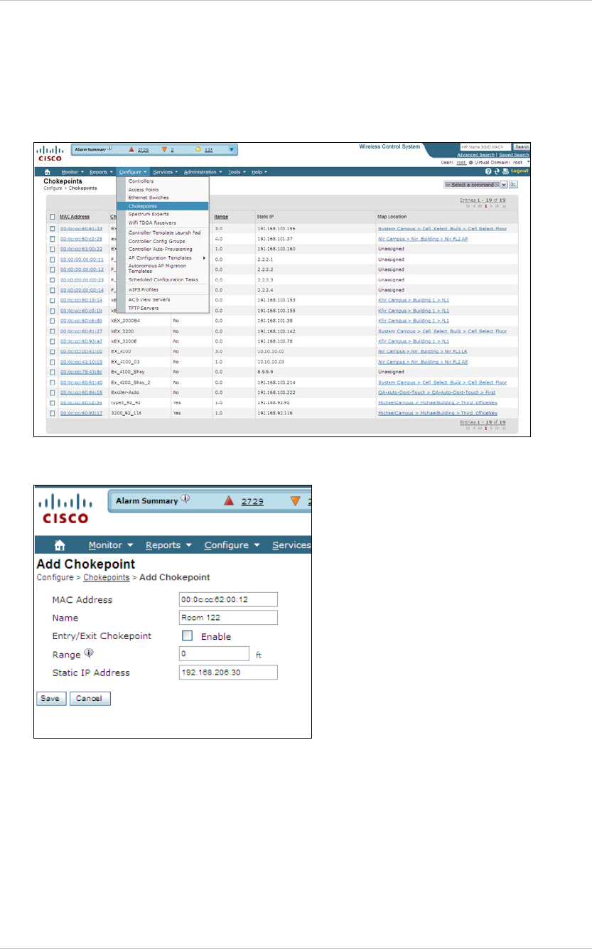
Configuring the Controller via Cisco MSE
Follow this procedure:
1. Open the WCS and select Configure, Chokepoints.
2. Select Add Chokepoint.
3. Enter the MAC address, Name and Static IP Address.
4. Click Save.
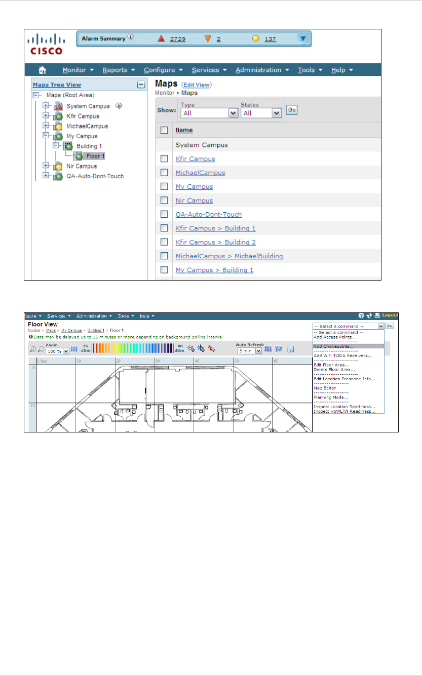
5. Select Monitor, Maps and then the relevant campus, building and floor.
EX5500 Controller Installation & Configuration Guide
23
6. Select Add Chokepoint and click Go.
7. Check the relevant Exciter and click OK. You are returned to the relevant floor
area.
8. Locate the added Exciter on the map and click Save.
9. Select Services, Synchronize Services and synchronize the relevant MSE.
10. Open System Manager and configure the Exciter.
EX5500 Controller Installation & Configuration Guide
24
Mounting the Controller and External LF
Antenna
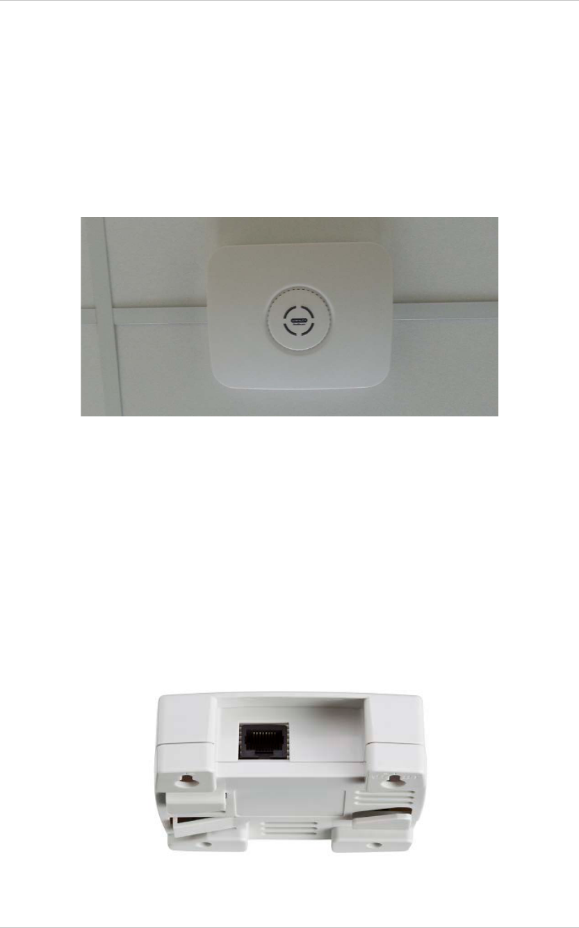
Fixing the Controller to a Floating Ceiling:
• Attach the device to the false ceiling using the ceiling mounts located on
the bottom casing of the device.
Figure 9: Controller mounted on a Floating Ceilings
Mounting the Controller on a Wall
Mount the Exciter with the Stanley Healthcare logo facing up.
• Attach the Controller to the wall using the two screw mounts on the
bottom casing.
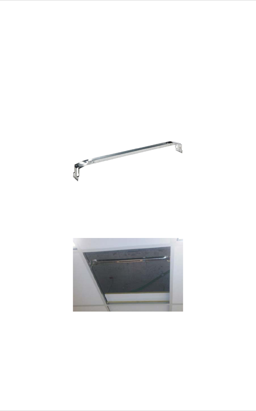
Fixing the External LF Antenna to a Floating Ceiling:
• Attach the antenna to the false ceiling using the ceiling mounts located on
the bottom casing.
Figure 10: External LF Antenna Mounting Brackets
EX5500 Controller Installation & Configuration Guide
25
Mounting the External LF Antenna on a Wall
• Attach the External LF Antenna to the wall using the two screw mounts
located on the bottom casing.
Mounting the Controller or External LF using the
Exciter Mounting Clip
The Exciter Mounting Clip (Figure 19) accessory is sold separately from the
Controller. It can be used to mount the Controller or the External LF in deployments
where mounting on the ceiling grid is not possible.
Figure 11: Exciter Mounting Clip (SKU: EXAC-140)
1. Position the Mounting Clip on a standard 60cm (24") grid false ceiling.
a. Snap the Mounting Clip onto the topside of the T-Grid using the ‘snaps’ on the
ends of the clip.
Figure 12: Exciter Mounting Clip positioned on a grid of a false cieling
2. Prepare the Ceiling Tile.
a. Measure and mark the required positions of the mounting screws on the ceiling
tile
b. Drill holes in the ceiling tile at the marked positions
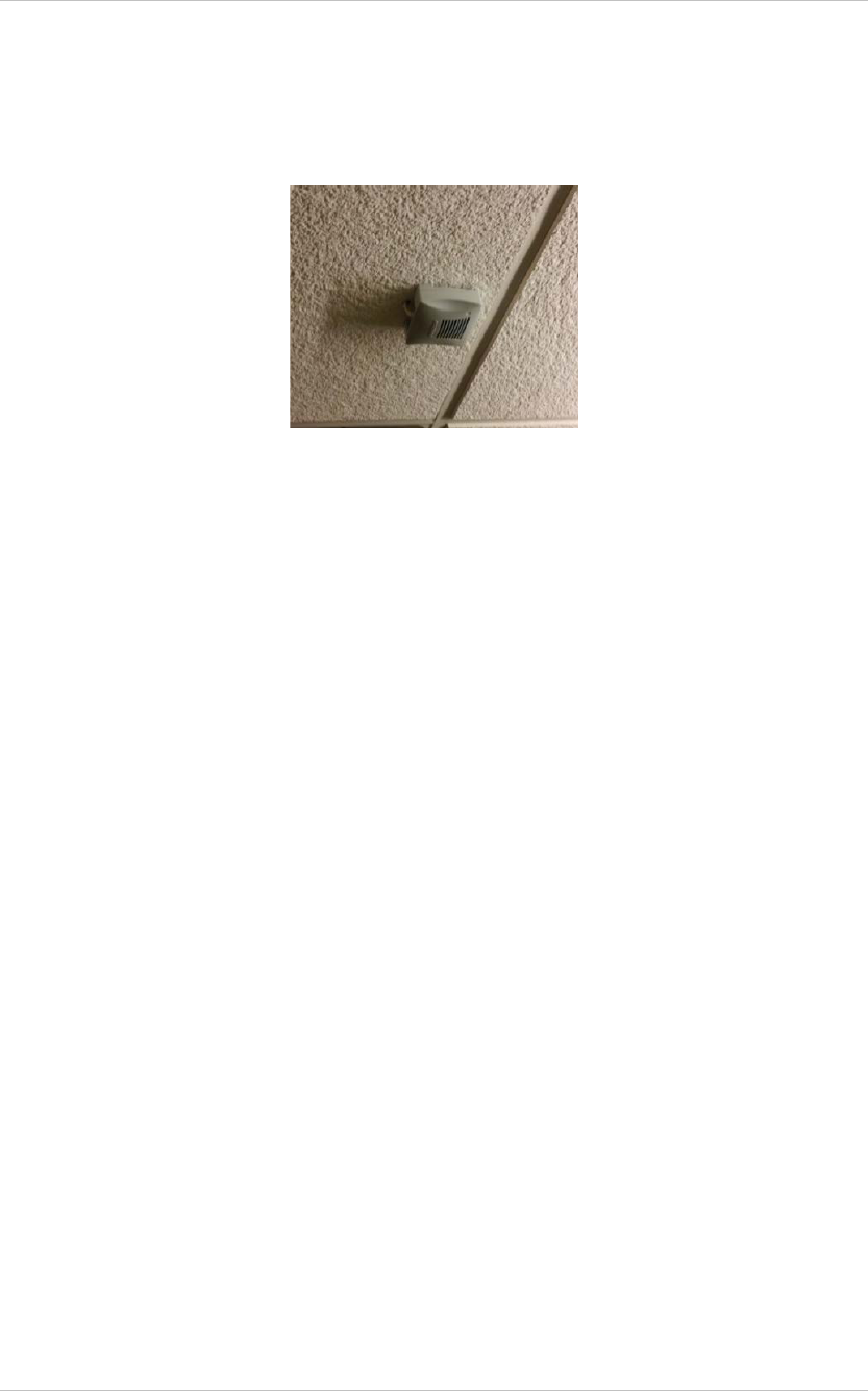
3. Mount the Controller or LF Antenna
a. Thread the screws (not provided) through the holes in the ceiling tile
EX5500 Controller Installation & Configuration Guide
26
b. Screw them into the Mounting clip. The screw heads should remain 2-3cm
below the ceiling tile.
c. Attach the Controller or LF Antenna using the two screw mounts on the bottom
casing.
Figure 13: External LF Antenna mounted using the Exciter Mounting Clip

EX5500 Controller Installation & Configuration Guide
27
EX5500 and Accessories Model Numbers
Product SKU Description
EX5500 Controller EX-5500 EX5500 Controller. Includes 48V DC input,
Ethernet and PoE interface
EX5500 Power
Supply ADP-047 AC/DC adaptor 45W 48V/1.0A 90-264VAC.
PoE Injector ADP-030-U 110/220 VAC to 48 VDC PoE Single-Port
Injector
Exciter Detector Tool EXD-1000 Tool for visualizing the effective LF Exciter
transmission field. Analyzes the Exciter
coverage during deployment. Includes a PC
application and detector hardware that can
be connected via USB to a PC.
External LF Antenna ANT-4200 External LF Antenna Device. Powered
directly from the Exciter. Includes mounting
plate and a ceiling mount.
Exciter Mounting Clip EXAC-140 Heavy-duty Mounting Clip for Exciters.
Snaps easily onto the topside of the T-Grid
of a false ceiling with a standard 24" span
grid. Enables mounting the Exciter using
screws.

EX5500 Controller Installation & Configuration Guide
28
EX5500 Specifications
Physical and Mechanical
• Dimensions: 192mm X 242mm X 61mm (6.1in x 7.1in x 1.8in)
• Weight: 450g (16oz)
• Housing: Polycarbonate and ABS
Range
• Adjustable from 0.5m (20 in) up to 6.5m (21.3ft) in intervals of 0.5m (20 in)
LF Channel
• 125kHz
• Field intensity limits: 37.3dBµA/m at 10m (ETSI)
• Propagation limits: 21.8dBµV/m at 300m (FCC)
• Modulation: ASK
Network Interface
• Ethernet (RJ-45)
Power
• Input voltage: 12, 24-48VDC
• PoE (802.3af) 48VDC
• Maximum power consumption: 10W.
• Maximum power consumption of External LF Antenna: 5W.
Environmental
• Operating temperature: 0 to 50 °C (32°F to 122°F)
• Humidity: 0 to 95%, non-condensing
EX5500 Controller Installation & Configuration Guide
29
FCC Compliance Statement
This device has been tested and found to comply with the limits for a Class B digital device, pursuant to Part 15 of
the FCC Rules. These limits are designed to provide reasonable protection against harmful interference in residential
installations. This equipment generates uses and can radiate radio frequency energy and, if not installed and used in
accordance with the instructions, may cause harmful interference to radio and television reception.
However, there is no guarantee that interference will not occur in a particular installation. If this device does cause
such interference, which can be verified by turning the device off and on, the user is encouraged to eliminate the
interference by one or more of the following measures:
– Re-orient or re-locate the receiving antenna.
– Increase the distance between the device and the receiver.
– Connect the device to an outlet on a circuit different from the one that supplies power to the receiver.
– Consult the dealer or an experienced radio/TV technician.
WARNING! Changes or modifications to this unit not expressly approved by the party responsible for compliance
could void the user’s authority to operate the equipment.
This device complies with FCC Rules Part 15 and with Industry Canada licence-exempt RSS standard(s).
Operation is subject to two conditions: (1) This device may not cause harmful interference, and (2) this device must
accept any interference that may be received or that may cause undesired operation.
Le present appareil est conforme aux CNR d'Industrie Canada applicables aux appareils radio exempts de licence.
L'exploitation est autorisee aux deux conditions suivantes :(1) l'appareil ne doit pas produire de brouillage, et (2)
l'utilisateur de l'appareil doit accepter tout brouillage radioelectrique subi, meme si le brouillage est susceptible d'en
compromettre le fonctionnement.

About Stanley Healthcare
Stanley Healthcare provides over 5,000 acute care hospitals and 12,000 long-term care organizations
with enterprise solutions that transform safety, security and operational efficiency. The Stanley
Healthcare EcoSystem enables customers to achieve organizational excellence and superior care in
five critical areas: Patient Safety, Security & Protection, Environmental Monitoring, Clinical
Operations & Workflow and Supply Chain & Asset Management. These integrated solutions are
complemented by consulting, training and Transformational Lean™ process reengineering. Stanley
Healthcare is proud to be part of Stanley Black & Decker, Inc. For more information, visit
www.StanleyHealthcare.com.
Stanley Healthcare
1300 Island Drive
Suite 202
Redwood City, CA 94065
Tel: +1 (650) 596-2994
Fax: +1 (650) 596-2969
E-mail: info@aeroscout.com
Europe, Middle East, Africa Office
Tel : +32 2 709 29 49
Fax : +32 15 30 80 99
E-mail: emea@aeroscout.com
Japan Office
Tel: +81 3 3556 9003
Fax: + 81 3 5875 3723
E-mail: info@aeroscout.co.jp
Latin America Office
Tel : +52 55 5001 5769
E-mail: latam@aeroscout.com
Asia-Pacific Sales
Tel : +1 650 596 2994
E-mail: apac@aeroscout.com
Australia and New Zealand Sales
Tel : +61 3 9038 8690
E-mail: anz@aeroscout.com