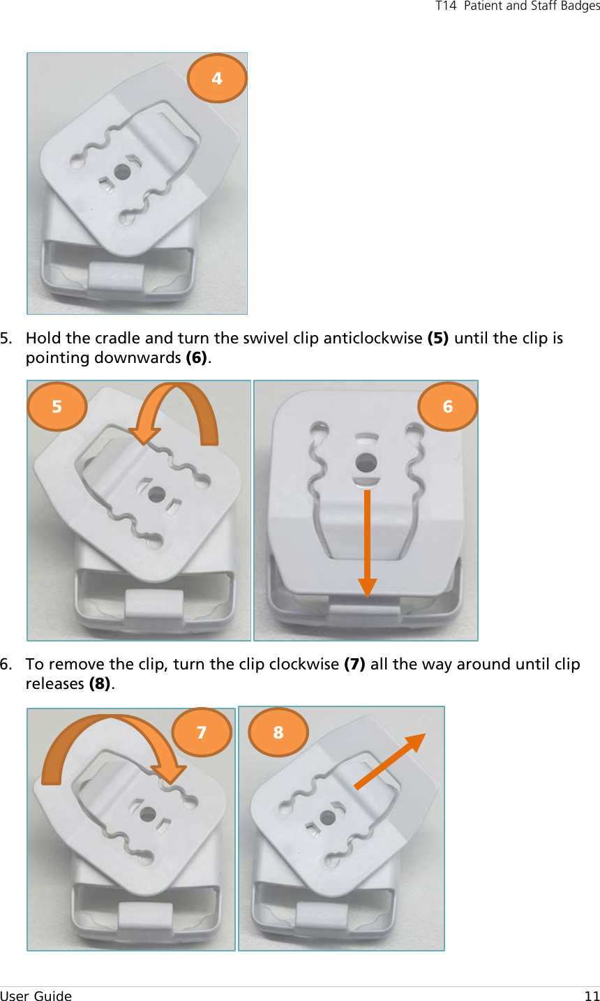
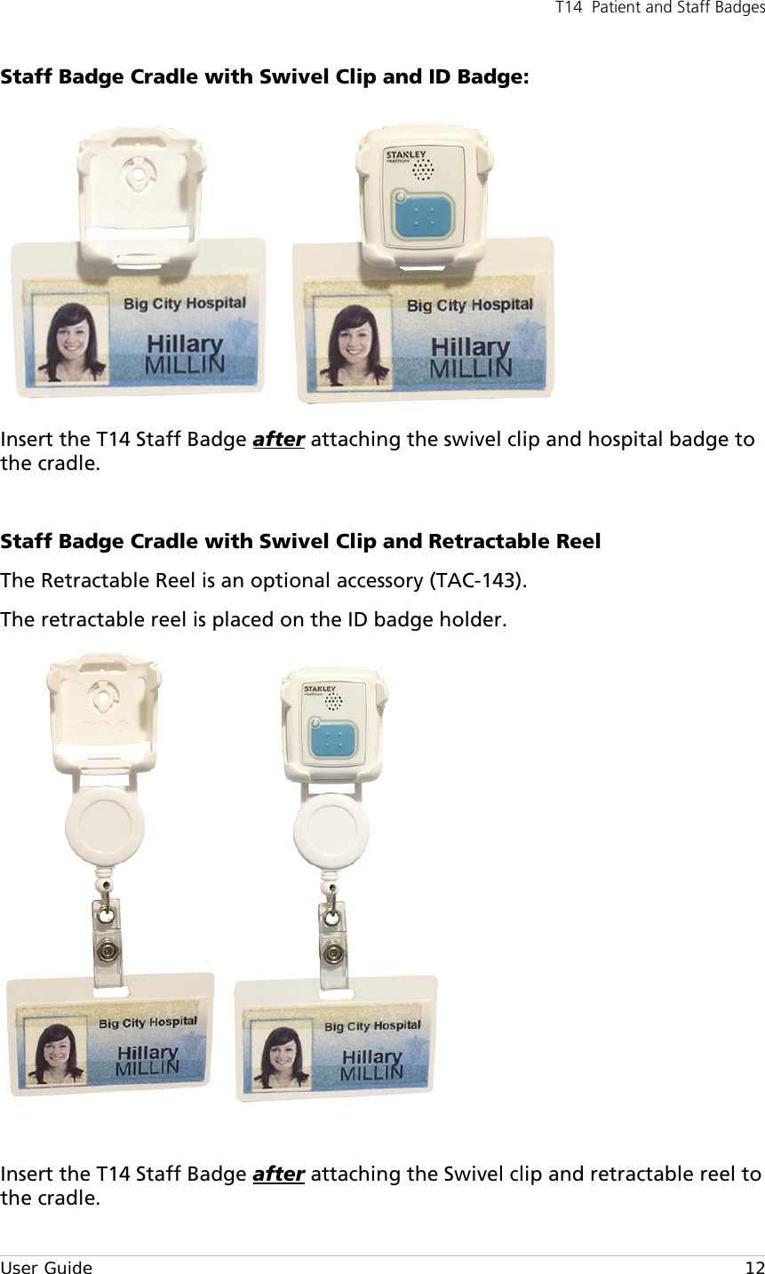
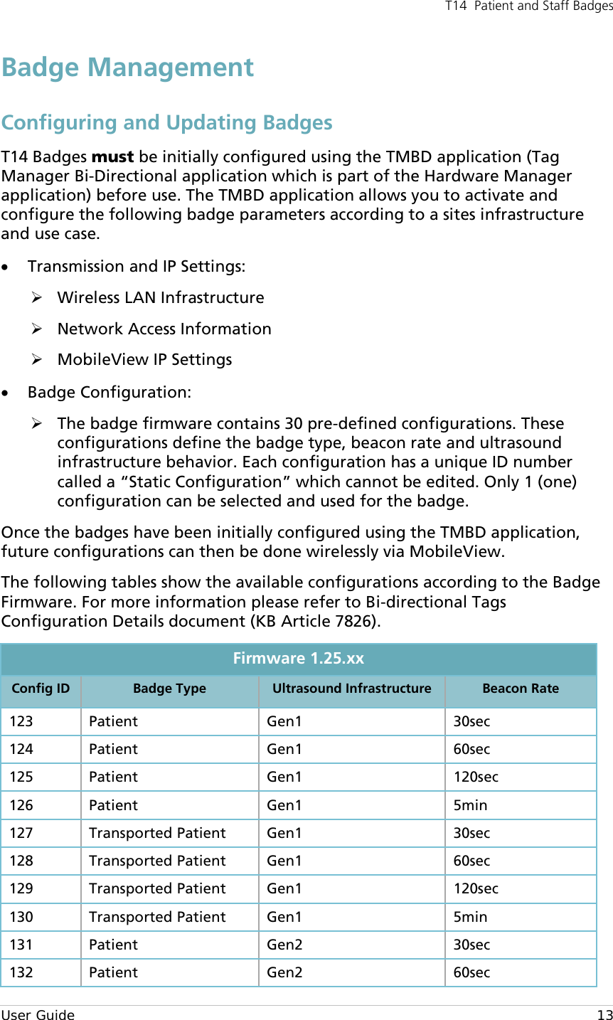
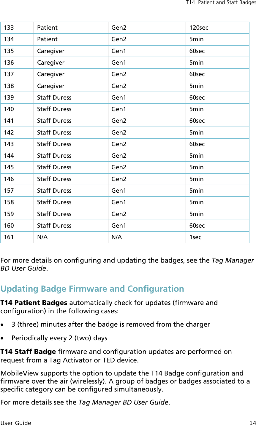
AeroScout TAG1410 TAG1410 Personal Tag User Manual T14 Tag User Guide

AeroScout TAG1410 Personal Tag T14 Tag User Guide

User Manual

                               T14 PATIENT AND STAFF BADGES USER GUIDE E version
   CAUTIONS AND WARNINGS • Electromagnetic radiation emitted from AeroScout Tags may interfere with critical care equipment. Please refer to the equipment manufacturer's user manuals for electromagnetic immunity guidance, and for separation distance recommendations, if applicable.  Use this link, https://www.stanleyhealthcare.com/support, to locate our published specifications for STANLEY Healthcare/AeroScout tag transmission frequencies and output power, or contact STANLEY Healthcare Technical Support at +1-800-380-8883 for assistance.  • Use of this equipment adjacent to or stacked with other equipment should be avoided because it could result in     Improper operation. If such use is necessary, this equipment and the other equipment should be observed to verify that they are operating normally.  • Portable RF communications equipment (including peripherals such as antenna cables and external antennas) should be used no closer than 1 cm to any part of the ME Equipment or ME System, including cables specified by the manufacturer. Otherwise, degradation of the performance of this equipment could result.  Disclaimer The information and know-how included in this document are the exclusive property of STANLEY Healthcare and are intended for the use of the addressee or the user alone. The addressees shall not forward to another their right of using the information, know-how or document forwarded herewith, in whole or in part in all matters relating or stemming from or involved therein, whether for consideration or without consideration, and shall not permit any third party to utilize the information, know-how or the documents forwarded herewith or copies or duplicates thereof, unless at the company’s consent in advance and in writing. Any distribution, advertisement, copying or duplication in any form whatsoever is absolutely prohibited. The Company reserves the right to sue the addressee, user and/or any one on their behalves, as well as third parties, in respect to breaching its rights pertaining to the intellectual rights in particular and its rights of whatever kind or type in the information, know-how or the documents forwarded by them herewith in general, whether by act or by omission. This document is confidential and proprietary to STANLEY Healthcare and is not to be distributed to any persons other than licensed AeroScout Visibility System users or other persons appointed in writing by STANLEY Healthcare. Trademark Acknowledgements AeroScout is a trademark of Stanley Black & Decker, Inc. or its affiliates. Other brand products and service names are trademarks or registered trademarks of their respective holders. Below is a partial listing of other trademarks or registered trademarks referenced herein:  Cisco™ is a trademark of Cisco Systems, Inc.  Sun, Sun Microsystems, the Sun Logo, Java, JRE and all other Sun trademarks, logos, product names, service names, program names and slogans that are referred to or displayed in this document are trademarks or registered trademarks of Sun Microsystems, Inc. in the United States and other countries. This product includes software developed by the Apache Software Foundation (http://www.apache.org/). This product includes code licensed from RSA Data Security Esper is a trademark of EsperTech, Inc. Jboss is a trademark of Red Hat Middleware, LLC.  Oracle and Java are registered trademarks of Oracle and/or its affiliates. Other names may be trademarks of their respective owners.  MS SQL Server 2005 and MS SQL Server 2008 are registered trademarks of Microsoft Corporation in the United States and/or other countries.  JasperSoft, the JasperSoft Logo, JasperReports, the JasperReports logo, JasperIntelligence, JasperDecisions, JasperAnalysis, Scope Center, Scope Designer, and JasperServer are trademarks or registered trademarks of JasperSoft, Inc. in the United States and other countries. Images of PLUM A+™, PLUM A+™ 3, LIFECARE PCA™, and SYMBIQ™ infusion systems are provided with permission of Hospira, Inc.  All rights reserved. ©2018 STANLEY Healthcare. All rights reserved. Doc: 0980-xxx-000 Rev A. Published: Draft 11.    KB Article: xxx.
T14  Patient and Staff Badges  User Guide  2 Table of Contents Overview .............................................................................................................. 3 Badge Descriptions .............................................................................................. 4 T14 Badge Features .............................................................................................. 5 Attaching the T14 Badges ................................................................................... 7 T14 Patient Badge Attachment Options ............................................................... 7 T14 Staff Badge Attachment Options .................................................................. 7 Badge Management........................................................................................... 13 Configuring and Updating Badges ..................................................................... 13 Updating Badge Firmware and Configuration .................................................... 14 Badge LED and Audio Indications ..................................................................... 15 Badge Maintenance ........................................................................................... 15 Battery .............................................................................................................. 15 Variances in Battery Life .................................................................................... 16 Battery Levels and Charging .............................................................................. 17 Battery Capacity ................................................................................................ 17 Cleaning the Badges ......................................................................................... 18 T14 Badge & Charger Models ............................................................................ 18 Badge Accessories .............................................................................................. 19 Specifications ..................................................................................................... 19 Tag Specifications ............................................................................................. 19 Compliance, Warnings and Warranty ............................................................... 21
T14  Patient and Staff Badges  User Guide     3 Overview The STANLEY Healthcare T14 Bi-directional Badges are components of the enterprise-level visibility solution based on standard Wi-Fi communication for location-based applications. The T14 Badges add further flexibility and scalability to locate patients and staff across a wide variety of applications. Once deployed, the badges use Wi-Fi bi-directional communication to receive firmware and configuration updates from MobileView. This removes the need to manually collect, update and re-deploy tags in the field. T14 Patient Badge comes with an embedded Ultrasound Receiver.   T14 Staff Badge comes with a Call Button, embedded Ultrasound Receiver and a buzzer.
T14  Patient and Staff Badges  User Guide     4 Badge Descriptions The following describes the parts of the T14 Badges: T14 Patient Badge:       Figure 1: T14 Patient Badge Descriptions  T14 Staff Badge:   Figure 2: T14 Staff Badge Descriptions        Front View Back View LED Indicator Ultrasound Receiver  Wrist band/ Badge cradle flanges Battery contacts Large Call Button Ultrasound Receiver LED Indicator Buzzer
T14  Patient and Staff Badges  User Guide     5 T14 Badge Features Beaconing and Bi-directional Communication  The T14 Badges utilize lightweight beaconing communication (for standard messages) and bi-directional Wi-Fi communication with full network association and authentication (for advanced applications). This unique combination provides a flexible and scalable solution for advanced applications. The badges can operate with up to four different network SSIDs in a secure or non-secure mode and is able to store up to two network IPs. The badges also support both static IP configuration and DHCP. Ultrasound Receiver  T14 Badges include an embedded ultrasound receiver able to receive signals from ultrasound Exciters. Exciters transmit ultrasound signals, which do not pass through walls, thus helping deliver location reports at room-level accuracy. T14 Badges capture the signals and report their exact location over the Wi-Fi network. Wi-Fi Security The Badges support 802.1x Enterprise security networks with PEAP-MSCHAPv2, WPA2-PSK with AES encryption and an open non-encrypted security mode. Rechargeable battery  The badges have a non-replaceable rechargeable battery. The badges are able to report their battery level which is displayed in MobileView (see Battery and Charging).  T14 Badges also have a motion sensor to conserve battery life when the badge is not in motion.  Badges are charged using the T14 Badge Charging Station (see the T14 Badge Charging Station User Guide for more information). *Battery life depends on badge type and configuration. Small Form Factor with Ergonomic Design  The badges small and ergonomic design provides ease of use for patient and staff comfit.  Egress Point Detection  When combined with STANLEY Healthcare Exciters, the T14 Badges provide instant notification when a tagged patient passes through an egress point, such as a gate, doorway or other tightly defined area. Rugged Performance  The T14 Badge enclosure is designed for durability, is water and dust proof and is able to withstand impacts*. The badges can be worn while taking a shower or bath. *See product specifications for IP rating.
T14  Patient and Staff Badges  User Guide     6 Visual & Audio Indication  T14 Badges include a dual-color LED which enables distinct visual indications for specific use cases. Audio indications (T14 Staff Badge only) occur when the call button is pressed or a Bi-directional acknowledgment is received (Staff Protection). Badge Management  T14 Badges are easily configured and activated wirelessly via the Tag Manager BD application and a Tag Activator or TED device, which are part of the Hardware Manager Kit (see badge accessories). The badges can then be reprogrammed using bi-directional communication via MobileView.  Call Button (T14 Staff Badges only)  T14 Staff Badges include a call button that can trigger an event in MobileView. MobileView events can be defined according to specific button press patterns, such as long press, short press and double press.
T14  Patient and Staff Badges  User Guide     7 Attaching the T14 Badges  Note Note the following about Ultrasound tags: • Make sure that the microphone on the front cover of the badge is uncovered at all times. • Avoid placing the badge where it can be constantly knocked by a metal or plastic object, such as a staff ID badge. Failing to do so may cause a disruption with the Ultrasound signal. • The T14 Staff Badge should be used with the T14 Staff Badge cradle (TAC-144). The cradle has ‘microphone protectors’ which help to avoid covering the microphone. T14 Patient Badge Attachment Options T14 Patient Badges are easily secured to a patient’s wrist using standard hospital bands, up to a width of 15mm, or worn using a T14 Badge cradle.                   Figure 3: T14 Patient Badge Attached to a Patient’s Wrist / T14 Badge Cradle with clip T14 Staff Badge Attachment Options T14 Staff Badges are worn by staff members using the T14 Staff Badge cradle with either the swivel clip or vinyl clip (TAC-144).   Figure 4: T14 Staff Badge Attached to a staff member’s scrubs.
T14  Patient and Staff Badges  User Guide     8  Using the Staff Badge Cradle with the Vinyl Clip  Insert the T14 Staff Badge after attaching the vinyl clip and hospital badge to the cradle. TAC-144 – Pack includes Cradle, Swivel clip and Vinyl clip ID badge holder Cradle Assembly Options Vinyl clip flange
T14  Patient and Staff Badges  User Guide     9 Staff Badge Cradle with a Vinyl Clip and Retractable Reel The Retractable Reel is an optional accessory (TAC-143). The retractable reel is placed on the ID badge holder.  Insert the T14 Staff Badge after attaching the vinyl clip and retractable reel to the cradle.     ID badge holder
T14  Patient and Staff Badges  User Guide    10 Using the Staff Badge Cradle with Swivel Clip The Swivel clip is inserted into the back of the cradle as follows: 1. Turn the cradle over and make sure the cradle’s flange is pointing upward (1). 2. Hold the swivel clip with the clip part pointing up and at a slight angle (2).  3. Place the swivel clip directly over the cradle (3).   4. The swivel clip should insert into the cradle opening (4). 1 2 3
T14  Patient and Staff Badges  User Guide    11  5. Hold the cradle and turn the swivel clip anticlockwise (5) until the clip is pointing downwards (6).  6. To remove the clip, turn the clip clockwise (7) all the way around until clip releases (8).  4 5 6 7 8
T14  Patient and Staff Badges  User Guide    12 Staff Badge Cradle with Swivel Clip and ID Badge:  Insert the T14 Staff Badge after attaching the swivel clip and hospital badge to the cradle.  Staff Badge Cradle with Swivel Clip and Retractable Reel The Retractable Reel is an optional accessory (TAC-143). The retractable reel is placed on the ID badge holder.   Insert the T14 Staff Badge after attaching the Swivel clip and retractable reel to the cradle.
T14  Patient and Staff Badges  User Guide    13 Badge Management Configuring and Updating Badges T14 Badges must be initially configured using the TMBD application (Tag Manager Bi-Directional application which is part of the Hardware Manager application) before use. The TMBD application allows you to activate and configure the following badge parameters according to a sites infrastructure and use case. • Transmission and IP Settings:  Wireless LAN Infrastructure  Network Access Information  MobileView IP Settings • Badge Configuration:  The badge firmware contains 30 pre-defined configurations. These configurations define the badge type, beacon rate and ultrasound infrastructure behavior. Each configuration has a unique ID number called a “Static Configuration” which cannot be edited. Only 1 (one) configuration can be selected and used for the badge. Once the badges have been initially configured using the TMBD application, future configurations can then be done wirelessly via MobileView. The following tables show the available configurations according to the Badge Firmware. For more information please refer to Bi-directional Tags Configuration Details document (KB Article 7826). Firmware 1.25.xx Config ID Badge Type Ultrasound Infrastructure Beacon Rate 123 Patient Gen1 30sec 124 Patient  Gen1 60sec 125 Patient Gen1 120sec 126 Patient Gen1 5min 127 Transported Patient Gen1 30sec 128 Transported Patient Gen1 60sec 129 Transported Patient Gen1  120sec 130 Transported Patient Gen1 5min 131 Patient Gen2  30sec 132 Patient Gen2  60sec
T14  Patient and Staff Badges  User Guide    14 133 Patient Gen2  120sec 134 Patient Gen2  5min 135 Caregiver Gen1 60sec 136 Caregiver Gen1 5min 137 Caregiver Gen2  60sec 138 Caregiver Gen2  5min 139 Staff Duress Gen1 60sec 140 Staff Duress Gen1 5min 141 Staff Duress Gen2 60sec 142 Staff Duress Gen2 5min 143 Staff Duress Gen2 60sec 144 Staff Duress Gen2 5min 145 Staff Duress Gen2 5min 146 Staff Duress Gen2 5min 157 Staff Duress Gen1 5min 158 Staff Duress Gen1 5min 159 Staff Duress Gen2 5min 160 Staff Duress Gen1 60sec 161 N/A N/A 1sec  For more details on configuring and updating the badges, see the Tag Manager BD User Guide. Updating Badge Firmware and Configuration T14 Patient Badges automatically check for updates (firmware and configuration) in the following cases: • 3 (three) minutes after the badge is removed from the charger • Periodically every 2 (two) days T14 Staff Badge firmware and configuration updates are performed on request from a Tag Activator or TED device.  MobileView supports the option to update the T14 Badge configuration and firmware over the air (wirelessly). A group of badges or badges associated to a specific category can be configured simultaneously.  For more details see the Tag Manager BD User Guide.
T14  Patient and Staff Badges  User Guide    15 Badge LED and Audio Indications T14 Badges include a dual-color LED (red and green) for visual indications. Audio indications are only available on the T14 Staff Badge which contains a buzzer.  These indications are described in the table below. The following symbols are used: —     = Long blink -         = Short blink .        = Quick flash T14 Staff Badge Button Presses LED Indications Short Press 1 short green blink ( - ) Long Press 1 long green blink (—) Double Press 2 short green blinks ( -  - ) T14 Staff Badge Audio Indications  Audio Indications Staff Duress Alert Audio indication Staff Assist Audio indication Acknowledgement Audio indication  Test Station   Audio indication Badge Maintenance Battery  T14 Badges have a non-replaceable rechargeable battery* and is charged using the T14 Badge Charging Station.  *Battery life depends on configuration and use cases.  The following table shows the battery life estimation based on a site’s infrastructure and available beacon rates:
T14  Patient and Staff Badges  User Guide    16 Beacon rate / Use case LF Environment (Non-Ultrasound) Ultrasound and LF Environment 5min 3 weeks 2 weeks 2min  2-3 weeks  1-2 weeks 1min 2 weeks 1 week 30sec  1-2 weeks < 1 week Variances in Battery Life Variances in battery life are based on solution type and usage and is calculated based on typical use cases.  Note Actual results may vary, up to 50%, due to the following: • Shift changes  • Local LF interference  • Extensive LF environments- such as increased time under LF • Changes in badge usage & time in storage before use • Changes in transmission interval • Bay separation setup   The following table shows the calculated battery life estimation based on a 5 minute beacon rate: Use Case US Environment Estimated Battery Life  Nurse Call / Patient Flow (Staff Badge) US Gen 1  2-3 weeks US Gen 2 2 weeks  Nurse call / Patient Flow (Patient Badge) US Gen 1  2-3 weeks US Gen 2 3 weeks Hand Hygiene US Gen 1  2-3 weeks US Gen 2 2 weeks
T14  Patient and Staff Badges  User Guide    17 Battery Levels and Charging The badges have the following 3 (three) battery levels that are shown in MobileView: • High – Indicates the badge has more than 30% battery capacity  • Medium – Indicates the badge has between 10-30% battery capacity • Low – Indicates the badge has less than 10% battery capacity  Note It is recommended to charge the badges during the Medium level or after a week of use, whichever comes first.  Badges are recharged using the T14 Badge Charging Station. Please refer to the T14 Badge Charging Station User Guide. Battery Capacity The Badge’s battery capacity degrades after a period of time, depending on the number of charge cycles (see table below). A charge cycle means using all the battery's capacity. Number of Charges Badge Battery Capacity 300 80% 400 75% 500 70% 600 65%  The reduction in capacity is much slower when the battery is partly discharged.  For T14 Badges, the battery is partly discharged if the badge is used for less than a week and is recharged again. When the operating time of a charged battery is significantly reduced, the badge should be disposed of according to facility procedures in your jurisdiction.  WARNING: This device contains a lithium battery. Do not force open, heat to 212°F (100°C), or dispose of in fire.
T14  Patient and Staff Badges  User Guide    18 Cleaning the Badges For approved cleaning methods and products, please refer to the Tag Maintenance Cleaning & Sanitizing Guide KB Article 8269.  ATTENTION: When cleaning, please pay special attention to the badges’ battery contacts. The battery contacts should be clear of dirt at all times.  T14 Badge & Charger Models Badge / Charger Model Badge Description PMN: TAG1410 T14 Tag Product Marketing Number SKU: TAG-1410-CUB Includes Call Button, Ultrasound Receiver and Buzzer  SKU: TAG-1410-U Includes Ultrasound Receiver  SKU: CGS-1400 T14 Badge Charging Station          Battery Contacts
T14  Patient and Staff Badges  User Guide    19 Badge Accessories Accessory Model / KB Article T14 Badge Cradle with vinyl clip (50 pack) SKU: TAC-140 T14 Staff Badge Cradle with back clip (20 pack) SKU: TAC-144 Retractable Badge reel for the T14 Staff Badge cradle (20 pack) SKU: TAC-143 Tag Wrist Strap (50 pack) SKU: TAC-223 T14 Heavy Duty Wrist Straps (50 pack) SKU: TAC-224 T14 Badge plastic housing with Ultrasound and Call Button (20 pack) SKU: TGH-1410-CU Hardware Manager Kit for the configuration of Tags and Exciters SKU: HWM-1000 Bi-directional Tags Firmware Versions download KB Article 7606   Specifications Tag Specifications Range • Outdoor range: Up to 200m (650 feet) • Indoor range: Up to 80m (260 feet) Physical and Mechanical • Dimensions: 1.6 x 1.4 x 0.6 inch (41x 36 X 15 mm) • Weight: 16g (0.56oz) Radio • 802.11 radio (2.4 GHz); b/g compliant  • Low frequency receiver for chokepoint detection (125kHz) • Transmission power: up to +16dBm (~40mW) • Patented clear channel sensing avoids interference with wireless networks
T14  Patient and Staff Badges  User Guide    20 Wi-Fi Security Modes:  • Open, non-encrypted • WPA2-PSK(AES) • 802.1x Enterprise security (PEAP-MSCHAPv2) Ultrasound Receiver  • Frequency 40KHZ  Environmental Specifications • Temperature: 0°C to 50°C (32°F to 122°F) • Humidity: 0% to 95% RH non-condensing • Ingress Protection Rating: IP-67 • Charging mode ambient temperature up to 40 ºC Electrical • 4.2V Lithium Polymer rechargeable battery (non-replaceable) • Battery life: up to 3 weeks, depending on badge type and configuration.  Programmability • Badge configurations* • Transmission channels • IP Settings *After initial setup, configuration changes are done over-the-air via MobileView Certification • Radio:  FCC Part 15, sub-part C class B, sub-part B EN 300-328, EN 300-330, EN 301-489, RSS 210 (Canada) • Safety: CE, cTUVus (EN60950) EN 60601-1-Rev3
T14  Patient and Staff Badges  User Guide    21 Compliance, Warnings and Warranty GENERAL COMPLIANCE NOTES • The T14 Tag has no direct clinical function or essential performance • The device is intended for use in any environment incl. healthcare and industrial • The device’s electric magnetic distributions have no direct impact on persons • The device has passed FCC and SAR regulations and can be attached to equipment or persons. • The device is battery powered and is not connected to any accessories while in use   EMISSION LIMITS PER ENVIRONMNET
T14  Patient and Staff Badges  User Guide    22 EMC Information Table 1 The TAG1410 is intended for use in the electromagnetic environment specified below. The customer or the user of the TAG1410 should assure that it is used in such an environment. Emissions test Compliance Electromagnetic environment – guidance RF emissions CISPR 11 Group 1 The TAG1410 uses RF energy only for its internal function. Therefore, its RF emissions are very low and are not likely to cause any interference in nearby electronic equipment. RF emissions CISPR 11 Class B The TAG1410 is suitable for use in all establishments, including domestic establishments and those directly connected to the public low voltage power supply network that supplies buildings used for domestic purposes. Harmonic emissions IEC 61000-3-2  Not Applicable Voltage fluctuations/ flicker emissions IEC 61000-3-3 Not Applicable  Table 2 The TAG1410 is intended for use in the electromagnetic environment specified below. The customer or the user of the TAG1410 should assure that it is used in such an environment. Immunity Test IEC 60601 Test Level  Compliance level Electromagnetic environment – guidance Electrostatic discharge (ESD) IEC 61000-4-2 ± 8 kV contact ± 2 kV, ± 4 kV, ± 8 kV, ± 15 kV air ± 8 kV contact ± 2 kV, ± 4 kV, ± 8 kV, ± 15 kV air Floors should be wood, concrete or ceramic tile. If floors are covered with synthetic material, the relative humidity should be at least 30 %. Electrical fast transient/burst IEC 61000-4-4 Not Applicable Not Applicable    Surge IEC 61000-4-5  Not Applicable Not Applicable
T14  Patient and Staff Badges  User Guide    23 Voltage dips, short interruptions and voltage variations on power supply input lines IEC 61000-4-11 Not Applicable Not Applicable  Power frequency (50/60 Hz) magnetic field IEC 61000-4-8 30 A/m 30 A/m Power frequency magnetic fields should be at levels characteristic of a typical location in a typical commercial or hospital environment. NOTE UT is the a.c. mains voltage prior to application of the test level.
T14  Patient and Staff Badges  User Guide    24 Table 3 The TAG1410 is intended for use in the electromagnetic environment specified below. The customer or the user of the TAG1410 should assure that it is used in such an environment. Immunity Test IEC 60601 Test Level Compliance level Electromagnetic environment – guidance Conducted RF IEC61000-4-6 Radiated RF IEC 61000-4-3 Not Applicable 10 V/m 80 MHz to 2,7 GHz Not Applicable 10 V/m 80 MHz to 2,7 GHz Portable and mobile RF communications equipment should be used no closer to any part of the TAG1410, including cables, than the recommended separation distance calculated from the equation applicable to the frequency of the transmitter. Recommended separation distance   𝑑=1210 √𝑃= 1.2√𝑃    80 MHz to 800 MHz  𝑑=2310 √𝑃= 2.3√𝑃    800 MHz to 2.7 GHz  Where P is the maximum output power rating of the transmitter in watts (W) according to the transmitter manufacturer and d is the recommended separation distance in metres (m) a. Field strengths from fixed RF transmitters, as determined by an electromagnetic site survey, b should be less than the compliance level in each frequency range.  Interference may occur in the vicinity of equipment marked with the following symbol:  NOTE 1 At 800 MHz, the higher frequency range applies. NOTE 2 These guidelines may not apply in all situations. Electromagnetic propagation is affected by absorption and reflection from structures, objects and people.
T14  Patient and Staff Badges  User Guide    25 a The compliance levels in the frequency range 80 MHz to 2,7 GHz are intended to decrease the likelihood that mobile/portable communications equipment could cause interference if it is inadvertently brought into patient areas. For this reason, an additional factor of 10/3 has been incorporated into the formulae used in calculating the recommended separation distance for transmitters in these frequency ranges. b Field strengths from fixed transmitters, such as base stations for radio (cellular/cordless) telephones and land mobile radios, amateur radio, AM and FM radio broadcast and TV broadcast cannot be predicted theoretically with accuracy. To assess the electromagnetic environment due to fixed RF transmitters, an electromagnetic site survey should be considered. If the measured field strength in the location in which the TAG1410 is used exceeds the applicable RF compliance level above, the TAG1410 should be observed to verify normal operation. If abnormal performance is observed, additional measures may be necessary, such as re-orienting or relocating the TAG1410.  Table 5 Recommended separation distances between portable and mobile RF communications equipment and the TAG1410 The TAG1410 is intended for use in an electromagnetic environment in which radiated RF disturbances are controlled. The customer or the user of the TAG1410 can help prevent electromagnetic interference by maintaining a minimum distance between portable and mobile RF communications equipment (transmitters) and the TAG1410 as recommended below, according to the maximum output power of the communications equipment. Rated Maximum Output Power of Transmitter W Separation distance according to frequency of transmitter m 80 MHz to 800 MHz 𝑑=1210√𝑃= 1.2√𝑃  800 MHz to 2,7 GHz 𝑑=2310 √𝑃= 2.3√𝑃 0.01   0.1   1   10   100   For transmitters rated at a maximum output power not listed above, the recommended separation distance d in metres (m) can be estimated using the equation applicable to the frequency of the transmitter, where P is the maximum output power rating of the transmitter in watts (W) according to the transmitter manufacturer. NOTE 1 At 800 MHz, the separation distance for the higher frequency range applies. NOTE 2 An additional factor of 10/3 has been incorporated into the formulae used in calculating the recommended separation distance for transmitters in the the frequency range 80 MHz to 2,7 GHz to decrease the likelihood that mobile/portable
T14  Patient and Staff Badges  User Guide    26 communications equipment could cause interference if it is inadvertently brought into patient areas. NOTE 3 These guidelines may not apply in all situations. Electromagnetic propagation is affected by absorption and reflection from structures, objects and people.  Table Immunity to RF Wireless Communication Equipment Test Frequency Band  Service  Modulation Maximum Power Distance Immunity Test Level Compliance Level (MHz) (MHz)   (W) (m) (V/m) (V/m) 385 380-390 TETRA 400 Pulse Modulation 18 Hz 1.8 0.3 27 27 450 430-470 GMRS 460, FRS 460 FM ± 5 kHz Deviation 1 kHz sine 2  0.3 28 28 710 704-787 LTE Band 13, 17 Pulse Modulation 217 Hz 0.2 0.3  9  9 745 780 810 800-960 GSM 800/900, TETRA 800, iDEN 820, CDMA 850, LTE Band 5 Pulse Modulation 18 Hz 2  0.3 28 28 870 930 1720 1700-1990 GSM 1800; CDMA 1900; GSM 1900; DECT; LTE Band 1, 3, 4, 25; UMTS Pulse Modulation 217 Hz 2  0.3 28 28 1845 1970 2450 2400-2570 Bluetooth, WLAN, 802.11 b/g/n, RFID 2450, LTE Band 7  Pulse Modulation 217 Hz 2  0.3 28 28
T14  Patient and Staff Badges  User Guide    27 5240 5100-5800 WLAN 802.11 a/n Pulse Modulation 217 Hz 2  0.3  9  9 5500 5785  FCC STATEMENT This equipment has been tested and found to comply with the limits for a Class B digital device, pursuant to Part 15 of the FCC rules. These limits are designed to provide reasonable protection against harmful interference in a residential installation. This equipment generates uses and can radiate radio frequency energy and, if not installed and used in accordance with the instructions, may cause harmful interference to radio communications. However, there is no guarantee that interference will not occur in a particular installation. If this equipment does cause harmful interference to radio or television reception, which can be determined by turning the equipment off and on, the user is encouraged to try to correct the interference by one or more of the following measures: a) Reorient or relocate the receiving antenna. b) Increase the separation between the equipment and receiver. c) Connect the equipment to an outlet on a circuit different from that to which the receiver is connected. d) Consult the dealer or an experienced radio/TV technician. This device complies with Part 15 of the FCC Rules.                    Operation is subject to the following two conditions: a) This device may not cause harmful interference b) This device must accept any interference received, including interference that may cause undesired operation.  FCC Warning  Modifications not expressly approved by the manufacturer could void the user authority to operate the equipment under FCC Rules.   WARNING:  This device complies with Part 15 of the FCC Rules and RSS-210 of Industry and Science Canada. Operation is subject to the following two conditions: (1) This device may not cause harmful interference, and (2) this device must accept any interference received, including interference that may cause undesired operation.  This device complies with Industry Canada license-exempt RSS standard(s). Operation is subject to the following two conditions: (1) this device may not cause interference, and (2) this device must accept any interference, including interference that may cause undesired operation of the device.  Le présent appareil est conforme aux CNR d'Industrie Canada applicables aux appareils radio exempts de licence. L'exploitation est autorisée aux deux conditions suivantes : (1) l'appareil ne doit pas produire de brouillage, et (2) l'utilisateur de l'appareil doit accepter tout brouillage radioélectrique subi, même si le brouillage est susceptible d'en compromettre le fonctionnement.
T14  Patient and Staff Badges  User Guide    28 STANLEY Healthcare (“STANLEY”) Standard Warranty and Disclaimer  For STANLEY Healthcare AeroScout® Products (“Products”)  Limited Warranty and Disclaimer.  STANLEY warrants that commencing from the date of delivery to Customer and continuing for a period of one (1) year thereafter (the “Warranty Period”), the hardware components of STANLEY Healthcare AeroScout® Products (the “Hardware”) will be free from defects in material and workmanship under normal use subject to the terms hereof. The date of shipment of the Hardware by STANLEY is set forth on the packaging material in which the Hardware is shipped. This limited warranty extends only to the original user of the Hardware. Customer's sole and exclusive remedy and the entire liability of STANLEY and its suppliers under this limited warranty will be, at STANLEY’s or its service center's option, shipment of replacement Hardware components within the Warranty Period or a refund of the purchase price if the Hardware is returned to the party supplying it to Customer, if different than STANLEY, freight and insurance prepaid. STANLEY replacement parts used in Hardware repair may be new or equivalent to new, and STANLEY reserves the right to provide replacement Hardware components of similar form and function, as long as the functionality is equal or better than Customer’s original Hardware components. STANLEY’s obligations hereunder are conditioned upon the return of affected Hardware in accordance with STANLEY’s then-current Return Material Authorization (RMA) procedures.  Notwithstanding the foregoing, the warranty for TAG Hardware specifically designated for sterilization via autoclave or other sterilization methods shall have a warranty period of 350 sterilization cycles from the date of delivery; provided, however, that sterilization outside of environmental specifications approved in any applicable user documentation voids all warranties.  Extended Warranty: STANLEY offers an extended warranty, for a fee, on AeroScout products. Within the one (1) year of the standard warranty, additional warranty of two (2) years may be purchased. Additional warranty years may only be purchased once within the first one (1) year, or prior to warranty expiration. A maximum of three (3) total warranty years are available for Hardware.   Exclusions: The warranty set forth above will not apply if the Hardware or the Product (i) has been altered, except by STANLEY, (ii) has not been installed, operated, repaired, or maintained in accordance with instructions supplied by STANLEY, (iii) has been subjected to abnormal physical or electrical stress, misuse, negligence, or accident; or (iv) is provided for beta, evaluation, testing, or demonstration purposes for which STANLEY does not receive a payment of purchase price or license fee.  In addition, this warranty shall not cover the following: • Batteries (other than DOA -Dead On Arrival). • Plastics (including defects in appearance, cosmetics, decorative or structural items including framing and non-operative parts). • Tag Calibration. • Expenses related to removing or reinstalling the Products. • Defects or damage that result from the use of Non-STANLEY certified Products, Accessories, Software or other peripheral equipment. • Defects or damages resulting from service, testing, adjustment, installation, maintenance, alteration, or modification in any way by any party other than STANLEY, or its authorized service partners. • All software contained in or otherwise part of STANLEY Healthcare AeroScout® Products, which is covered by STANLEY’s separate software warranty contained in the separate software license agreement with respect to such Products.
T14  Patient and Staff Badges  User Guide    29  The warranty set forth above shall not be enlarged and no obligation or liability shall arise out of STANLEY’s rendering of technical advice, facilities or service in connection with Customer's purchase of the STANLEY Healthcare AeroScout® Products.    Except for the foregoing warranties, which shall be the exclusive warranties with respect to any Products, STANLEY MAKES NO WARRANTY OR REPRESENTATION OF ANY KIND, EXPRESS OR IMPLIED, WRITTEN OR ORAL,  REGARDING INFORMATION GIVEN OR THE PRODUCTS OR SERVICES SUPPLIED AND EXPRESSLY DISCLAIMS ALL EXPRESS AND IMPLIED WARRANTIES, REPRESENTATIONS AND CONDITIONS, INCLUDING WITHOUT LIMITATION ALL WARRANTIES AND CONDITIONS OF QUALITY, NON-INFRINGEMENT, MERCHANTABILITY AND SUITABILITY OR FITNESS FOR A PARTICULAR PURPOSE TO THE EXTENT PERMITTED BY LAW. STANLEY WILL NOT BE LIABLE FOR CONSEQUENTIAL, INCIDENTAL, INDIRECT OR PUNITIVE DAMAGES FOR ANY CAUSE OF ACTION, WHETHER IN CONTRACT, TORT OR OTHERWISE.  Consequential, incidental and indirect damages include, but are not limited to, lost profits, lost revenue and loss of business opportunity, whether or not STANLEY was aware or should have been aware of the possibility of these damages.
   About STANLEY Healthcare STANLEY Healthcare provides over 5,000 acute care hospitals and 12,000 long-term care organizations with enterprise solutions that create a safe, secure and efficient healthcare experience across life’s stages. The STANLEY Healthcare solution set enables customers to achieve organizational excellence and superior care in critical areas: Patient/Resident Safety, Security & Protection, Environmental Monitoring, Clinical Operations & Workflow and Supply Chain & Asset Management. These solutions are complemented by STANLEY Healthcare’s By Your Side™ Lifetime Customer Care commitment to ensure that every customer achieves success and realizes the full value of their investment, through consulting, training, implementation and integration services. STANLEY Healthcare is proud to be part of Stanley Black & Decker, Inc. For more information, visit stanleyhealthcare.com. Follow STANLEY Healthcare on Facebook, Twitter, LinkedIn and YouTube.  STANLEY Healthcare 130 Turner Street Building 3 Waltham, MA 02453 Tel: +1-888-622-6992 North America E-mail: stanleyhealthcare@sbdinc.com Asia-Pacific E-mail: stanleyhealthcare-asiapac@sbdinc.com Europe  E-mail: shs-uk@sbdinc.com Latin America E-mail: stanleyhealthcare-latam@sbdinc.com Middle East E-mail: stanleyhealthcare-MEA@sbdinc.com

Navigation menu