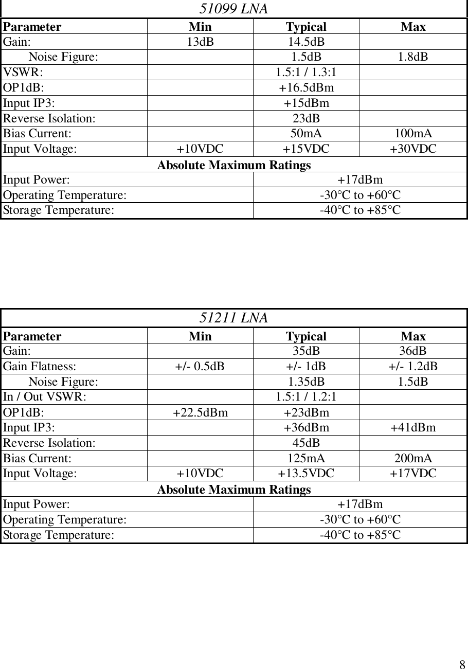
AeroComm 514830111 Cellular Over Fiber Cell Extender System User Manual Manual

Aerocomm Inc Cellular Over Fiber Cell Extender System Manual

Manual

CELLULAR FIBER OPTICALEXTENDER(Donor & Server Units)OPERATIONINSTRUCTION MANUALMODEL 51483-CMD Office:19516 Amaranth DriveGermantown, MD 20874Phone: 301-540-0700Fax: 301-540-5743NJ Office:464 Hudson TerraceEnglewood Cliffs, NJ 07632Phone: 201-227-0066Fax: 201-227-0067Email: mail@aerocomminc.comhttp://www.aerocomminc.comALL INFORMATION CONTAINED IN THIS DOCUMENT IS PROPRIETARY TO AEROCOMM, ANDSHALL NOT BE RELEASED, DISCLOSED OR DUPLICATED FOR ANY PURPOSE OTHER THENEVALUATION, INSPECTION, OR MAINTENANCE OF EQUIPMENT DELINEATED HEREIN.AEROCOMM IS NOT RESPONSIBLE FOR ANY EQUIPMENT REPAIRED OR ALTERED BY PERSONSNOT AUTHORIZED BY AEROCOMM, OR NOT IN ACCORDANCE WITH INSTRUCTIONS FURNISHEDBY AEROCOMM. AEROCOMM IS NOT RESPONSIBLE FOR EQUIPMENT RENDERED DEFECTIVE ASA RESULT OF MISUSE, IMPROPER REPAIR, OR ABNORMAL CONDITIONS OF OPERATION, NORDOES AEROCOMM ASSUME ANY LIABILITY FOR ANY CONSEQUENTIAL DAMAGE CAUSED BYSUCH EQUIPMENT.SERVICE CONTRACTS OR CUSTOMER ASSISTANCE AGREEMENTS ARE AVAILABLE FORAEROCOMM PRODUCTS THAT REQUIRE MAINTENANCE AND/OR REPAIR. AEROCOMM ALSOHAS AVAILABLE SERVICE AND CONSULTATION CONTRACTS FOR ENTIRE SYSTEMSCONFIGURATION.
2CELLULAR FIBER OPTICALEXTENDERMODEL 51483-C(824-849MHz: 869-894MHz)AEROCOMMAEROCOMM SMR SERVERRF O VER FIBERMO DE L 51 081 -02 -47RF OUTF/O T RX I NDI CATORSLA SE RLN AALARM INDICATORSA Wireless Systems CompanyFO  IN21F/ OPW RAM PF/ O LN APW RFO  OUTOFFPOWE ROFFONFU SEPCS SER VERRF O VER FIBERMO DE L 51 081 -02 -45RF OUTF/O T RX I NDI CATORSLA SE RLN AALARM INDICATORSA Wireless Systems CompanyFO  IN21PW RAM PF/ OF/ OPW RLN AFO  OUTONPOWE RFU SEAEROCOMMA Wireless Systems Co mpanyLA SE RPW RFO  INF/ OF/O T RX I NDI CATORSFO  OUTRF INBTSINT ERFA CEMO DE L 51 081 -02 -47RF O VER FIBEROFFSM R SERVERONOFFPOWE RFU SEAEROCOMMLA SE RPW RA Wireless Systems CompanyFO  INF/ OF/O T RX I NDI CATORSFO  OUTRF INBTSINT ERFA CEMO DE L 51 081 -02 -45RF O VER FIBERPOWE RONPCS SER VERFU SEDONOR SERVER
3TABLE OF CONTENTSI.  INTRODUCTION...........................................................................................................4PURPOSE OF MANUAL:..............................................................................................4MANUAL OUTLINE .....................................................................................................4GENERAL SYSTEM OVERVIEW:..............................................................................5II. SPECIFICATIONS.........................................................................................................6GENERAL SPECIFICATIONS......................................................................................6Service: CELLULAR..................................................................................................6SUB-ASSEMBLY SPECIFICATIONS:.........................................................................7AC231 ....................................................................... Error! Bookmark not defined.51099 LNA..................................................................................................................851211 LNA..................................................................................................................851098 LNA..................................................................................................................920dB Attenuator..........................................................................................................96dB Attenuator............................................................................................................9Duplexer....................................................................................................................10TX Filter....................................................................................................................10RX Filter....................................................................................................................10III.  INSTALLATION.......................................................................................................11RF CABLE CONNECTIONS.......................................................................................11FIBER OPTICAL CABLE CONNECTIONS...............................................................11IV.  OPERATION OF EQUIPMENT...............................................................................12V. MAINTENANCE SCHEDULE...................................................................................13CABLE INSPECTIONS:..............................................................................................13ENCLOSURE INSPECTIONS:....................................................................................13LED INSPECTIONS:....................................................................................................13VI.  THEORY OF OPERATION......................................................................................14VII.  TROUBLESHOOTING............................................................................................15SERVER UNIT..............................................................................................................15DONOR UNIT ..............................................................................................................16VIII.  RECOMMENDED SPARES..................................................................................17
4I.  INTRODUCTIONPURPOSE OF MANUAL:The purpose of this manual is to outline the installation, describe the operation,and assist in the maintenance and trouble-shooting of the CELLULAR Fiber OpticalExtender, Model 51483-C.MANUAL OUTLINESection II: Section II covers the general specification of the CELLULARFiber Optical Extender. This section outlines the general, mechanical andelectrical specifications including the module specifications (sub-assemblies).Section III:   Section III covers the instructions for installing the CELLULARFiber Optical Extender, site requirements, and equipment initialization.Section IV:   Section IV covers Operation of Equipment.Section V:   Section V is the recommended schedule of periodic maintenance ofCELLULAR Fiber Optical Extender.Section VI:   Section VI covers the general “Theory of Operations” of the logicand modules of CELLULAR Fiber Optical Extender. This section is designed toaid in understanding of the CELLULAR Fiber Optical Extender.Section VII:   Section VII consists of diagrams, tables and procedures to assist inthe troubleshooting of a CELLULAR Fiber Optical Extender. This section isdesigned to guide a technician in locating system fault(s) to the module. Includedin the section is a list of recommended test equipment.Section VIII:  Section VIII lists the recommended spare parts for theCELLULAR Fiber Optical Extender.
5GENERAL SYSTEM OVERVIEW:The AeroComm, Inc. Fiber Optic Booster Amplifier (Model#51483-C) can beused where CELLULAR Carrier Service is required but not accessible due to long ordifficult coaxial cable runs. It eliminates costly construction using coaxial cable. TheAeroComm, Inc. Model#51483-C converts the Carrier RF signal, enabling the use ofFiber Optic Cable which is easily routed to inaccessible areas and has much lower loss,where it is then reconverted back to Carrier RF signal.
6II. SPECIFICATIONSGENERAL SPECIFICATIONSService: CELLULARFrequency Range: Uplink: 824-849 MHz Downlink: 869-894 MHzNoise Figure: 6.3 dB Typical 7.0dB TypicalGain: 51 dB Min. 51dB Min.Delay: 5usec/KmOutput Power: +22 dBm +23 dBmInput Power (No Damage): -30 dBm Max -30 dBm MaxPower Consumption: 1.2 A @ 110 VAC Per Donor/ServerWeight: 21 lbs.Temperature: -25C to + 75 CSize: 19” Rack Mount Unit, 4U (7”H) x 18”RF Connectors: N-FemaleFiber Optic Connectors: FC/APCCable: 9/125 mm Single Mode FO CableEnclosure: 19” Rack Mount
7SUB-ASSEMBLY SPECIFICATIONS:RF TO FIBER MODULEParameter Min Typical MaxWavelength, peak: 1520nm1280nm 1550nm1310nm 1570nm1360nmBandwidth: 50MHZ 2000MHZFrequency Flatness:(800-2000MHZ) + / - 1.5dBIn & Out VSWR: 1.5:1 1.8:1RF Isolation, In-band: 40Spur Free Dynamic Range: 103dB/HZ 3/2 106dB/HZ 3/2RF Link Gain: -2dB 0dB +2dBNoise Figure  WM optionWA optionWB option34dB38dB42dBInput 3rd Order InterceptWM optionWA optionWB option+22dBm+26dBm+29dBmAbsolute MaximumsOperating Temperature: -30°C to +75°CStorage Temperature: -40°C to +85°CMaximum RF Input to Transmitter: +10dBmMaximum Optical Input to Receiver: 4mWD.C. Supply Voltage: 12 volts +\-5%
851099 LNAParameter Min Typical MaxGain: 13dB 14.5dBNoise Figure: 1.5dB 1.8dBVSWR: 1.5:1 / 1.3:1OP1dB: +16.5dBmInput IP3: +15dBmReverse Isolation: 23dBBias Current: 50mA 100mAInput Voltage: +10VDC +15VDC +30VDCAbsolute Maximum RatingsInput Power: +17dBmOperating Temperature: -30°C to +60°CStorage Temperature: -40°C to +85°C51211 LNAParameter Min Typical MaxGain: 35dB 36dBGain Flatness: +/- 0.5dB +/- 1dB +/- 1.2dBNoise Figure: 1.35dB 1.5dBIn / Out VSWR: 1.5:1 / 1.2:1OP1dB: +22.5dBm +23dBmInput IP3: +36dBm +41dBmReverse Isolation: 45dBBias Current: 125mA 200mAInput Voltage: +10VDC +13.5VDC +17VDCAbsolute Maximum RatingsInput Power: +17dBmOperating Temperature: -30°C to +60°CStorage Temperature: -40°C to +85°C
951098 Power AMPParameter Min Typical MaxGain: 28.5dB 30dB 31dBGain Flatness: +/- 0.4dB +/- 1.2dBNoise Figure: 2.3dB 3.7dBIn / Out VSWR: 1.5:1 / 1.2:1OP1dB: +35dB +36dBmInput IP3: +50dbm +52dBmInput Voltage: +12VDC +13.5VDC +18VDCBias Current: 1600mA 2000mAOperating Temperature -20°C +60°CAbsolute Maximum RatingsVCC: +20VDCInput Power: +5dBmCurrent: 2200mAOperating Temperature: -30°C to +70°CStorage Temperature: -40°C to +85°C20dB AttenuatorP/N: BW-S20W2Frequency: DC-18GHZAccuracy: ±0.60VSWR: L DC-4GHZ 1.20M 4-8GHZ 1.25U 8-12.4GHZ 1.30Power: 2W6dB AttenuatorP/N: BW-S6W2Frequency: DC-18GHZAccuracy: ±0.40VSWR: L DC-4GH 1.20M4-8GH 1.25U 8-12.4GHZ 1.30Power: 2Watts
10DuplexerP/N: 60024Receive: 821-851MHzTransmit: 866-895MHzPassband Insertion Loss: 1.0dB maximumChannel to Channel Isolation: 65dB minimumMaximum Transmit Power Handling:CW 20 wattsPeak Instantaneous 80 wattsPassband Return Loss: 15dB minimumOperating Temperature: -30 to +70°CDimensions: 2.00”W x 2.97”D x 5.00”HConnectors: SMA- FemaleTX FilterP/N: 5BCR12C-882.5/33-DPassband: 869-894MHZ3dB Passband: 34MHZPassband Insertion Loss: 2.5dB maximumRejection:DC - 849MHZ 60dB minimum849 - 859MHZ 30dB minimum914 – 3xFoMHZ 40dB minimumPassband Return Loss: 15dB minimumVSWR: 1.5:1 max.Connectors: SMA- FemaleRX FilterP/N: 5BCR12C-840.5/33-DPassband: 826-851MHZ3dB Passband: 34MHZPassband Insertion Loss: 2.5dB maximumRejection:DC - 806MHZ 60dB minimum806 - 816MHZ 30dB minimum871 - 3xFoMHZ 40dB minimumPassband Return Loss: 15dB minimumVSWR: 1.5:1 max.Connectors: SMA- Female
11III.  INSTALLATIONThe CELLULAR Fiber Optical Extender is housed in a 19” Rack Mountenclosure. Refer to Figure 1 for the installation block diagram.RF CABLE CONNECTIONS! The RF cable from Donor Antenna to the DONOR UNIT is connected to female N-Type Connector on the CELLULAR DONOR front panel RF PORT.! The RF cable from Server Antenna to the SERVER UNIT is connected to female N-Type Connector on the CELLULAR SERVER front panel RF PORT.FIBER OPTICAL CABLE CONNECTIONSThe FC/APC to FC/APC fiber cables is connected between Donor and Server front panel.! Donor FO OUT connects to the Server FO IN.! Donor FO IN connects to the Server FO OUT." Caution: The FC/APC Fiber Optic connector is a Keyed connector, if the Key is notmated properly the connector will not mate. Extreme caution must be maintained toavoid touching the end of the fiber optic connector and getting it dirty." Coaxial and Fiber Optic cables are supplied by user.AC POWER CONNECTIONSConnect AC Line Cord to the 110VAC Power Sources.D uplexerTXRXFOINPUTFOOU TPUTRFINPUTRFOU TPUTD uplexerTXRXRFINPUTRFOU TPUTFOINPUT FOOU TPUTRF / FOTranceiverAnacomA C231RF / FOTranceiverAnacomA C2315121151211RX Filter RX FilterTX Filter TX Filter5109951099 510985109820dB ATT20dB ATT 6dB ATT6dB ATTLNA Aerocom mLNA Aerocom mLNA Aerocom m Power AM PAerocom mPower AM PAerocom mDONOR UNIT SERV ER UNITCELLULAR  FOEXBLOCK DIAGRAMD onor AntennaServer AntennaF/O TRX INDICATORSFO OUTFO INRF PORTF/O      PWR      LASERFUSE ONOFFF/O TRX INDICATORSFO OUTFO INRF PORTF/O      PWR      LASERFUSE ONOFFALARM INDICATORSF/O      PWR      LNA    LNAAMP          2        1RF OVER FIBERCELL SERVERMODEL 51483-02-27PO WE RPO WE RRF OVER FIBERCEL L DO NO RMODEL 51483-02-28F/O      PWR      LNA    LNAAMP          2        1COMM PORT COMM PORTFIGURE 1
12IV.  OPERATION OF EQUIPMENTThe CELLULAR Fiber Optical Extender requires no operator settings foroperation. It is designed for unattended operation.The following is all that is necessary for operation:# Install# Connect# Turn-On# Watch LED
13V. MAINTENANCE SCHEDULEThe CELLULAR Fiber Optical Extender is designed for unattended operationrequiring minimal maintenance. General maintenance consists of equipment inspectionand operational tests. Periodical equipment tune-up and alignment is recommended.CABLE INSPECTIONS:The external and internal cables and connectors should be checked forindication of corrosion.ENCLOSURE INSPECTIONS:The interior of the enclosures should be inspected for evidence ofcondensation.LED INSPECTIONS:DONOR UNIT# POWER LED: ON# F/O TRX INDICATORSF/O LED: ONPWR LED: ONLASER LED: ON# ALARM INDICATORSF/O LED: GREENPWR AMP LED: OFFLNA2 LED: OFFLNA1 LED: OFF# COMM PORTNormal: Closed (Pin1 & Pin2)Fault: Open (Pin1 & Pin2)SERVER UNIT# POWER LED: ON# F/O TRX INDICATORSF/O LED: ONPWR LED: ONLASER LED: ON# ALARM INDICATORSF/O LED: GREENPWR AMP LED: OFFLNA2 LED: OFFLNA1 LED: OFF# COMM PORTNormal: Closed (Pin1 & Pin2)Fault: Open (Pin1 & Pin2)The performance of operations testing is recommended to be done semi-annually.Operational testing will indicate equipment status, determining if an alignment isnecessary.
14VI.  THEORY OF OPERATIONThe CELLULAR Fiber Optical Extender has two channels, one is Down Linkfrequencies from 869MHZ to 894MHZ, and the other is UP Link frequencies from824MHZ to 849MHZ. Both Up Link and Down Link signals are converted from RFsignals to optical signals then through the fiber optical cable to the far end and convertedback to RF signals. The AeroComm, Inc. Fiber Optic Booster Amplifier (Model#51483-C) can be used where CELLULAR Carrier Service is required but not accessible due tolong or difficult coaxial cable runs. It eliminates costly construction using coaxial cable.The AeroComm, Inc. Model# 51483-C converts the Carrier RF signal to optical signals,enabling the use of Fiber Optic Cable which is easily routed to inaccessible areas and hasmuch lower loss, where it is then reconverted back to Carrier RF signal.Caution: The user that changes or modifications not expressly approved by the partyresponsible for compliance could void the user’s authority to operate the device (CFR 47section 15.2)NOTE: This equipment has been tested and found to comply with the limits for a ClassA digital device, pursuant to part 15 of the FCC Rules. These limits are designed toprovide reasonable protection against harmful interference when the equipment isoperated in commercial environment. This equipment generates, uses and can radiateradio frequency energy and, if not installed and used in accordance with the instructionmanual, may cause harmful interference to radio communications. Operation of thisequipment in a residential area is likely to case harmful interference in which case theuser will be required to correct the interference at this own expense.
15VII.  TROUBLESHOOTINGThis Troubleshooting Procedure has been developed for the use of a trainedtechnician with knowledge of troubleshooting methodology in order to isolate faults tothe unit level.SERVER UNITProblem Solution1. Power LED is off a) Check Fuse, if fuse is ok go to next step.b) Check Power Supply 110VAC input, if 110VAC ispresent, go to next step.c) Check Power Supply +12VDC output. If +12 volt is notpresent, replace the Server Unit.2. PWR LED is off  (F/O TRX INDICATORS) a) Replace the Server Unit.3. LASER LED is off  (F/O TRX INDICATORS) a) Replace the Server Unit.4. F/O LED is off  (F/O TRX INDICATORS) a) to Problem 8.5. LNA1 LED is on  (ALARM INDICATORS) a) Replace the Server Unit.6. LNA2 LED is on  (ALARM INDICATORS) a) Replace the Server Unit.7. PWR AMP LED is on  (ALARM INDICATORS) a) Replace the Server Unit.8. F/O LED is red  (ALARM INDICATORS) a) Check the FC/APC Connectors and insure they aremated properly. Using a cotton swab cleaner, and alcoholclean the FC/APC connector. If F/O LED is still red, goto next step.b) Using a short FC/APC to FC/APC Fiber OpticPatchcord connect between FO IN and FO OUT. If LEDis still red, replace the Server Unit. If LED is green go tonext step.b) Check Fiber Optic Cable by using Fiber Test Meter, ifFiber Optic Cable is ok, the problem is on the DonorUnit.
16DONOR UNITProblem Solution1. Power LED is off a) Check Fuse, if fuse is ok go to next step.b) Check Power Supply 110VAC input, if 110VAC ispresent, go to next step.c) Check Power Supply +12VDC output. If +12 volt is notpresent, replace the Donor Unit.2. PWR LED is off  (F/O TRX INDICATORS) a) Replace the Donor Unit.3. LASER LED is off  (F/O TRX INDICATORS) a) Replace the Donor Unit.4. F/O LED is off  (F/O TRX INDICATORS) a) to Problem 8.5. LNA1 LED is on  (ALARM INDICATORS) a) Replace the Donor Unit.6. LNA2 LED is on  (ALARM INDICATORS) a) Replace the Donor Unit.7. PWR AMP LED is on  (ALARM INDICATORS) a) Replace the Donor Unit.8. F/O LED is red  (ALARM INDICATORS) a) Check the FC/APC Connectors and insure they aremated properly. Using a cotton swab cleaner, and alcoholclean the FC/APC connector. If F/O LED is still red, goto next step.b) Using a short FC/APC to FC/APC Fiber OpticPatchcord connect between FO IN and FO OUT. If LEDis still red replace the Donor Unit. If LED is green go tonext step.b) Check Fiber Optic Cable by using Fiber Test Meter, ifFiber Optic Cable is ok, the problem is on the ServerUnit.
17VIII.  RECOMMENDED SPARESWe recommend units be sent to factory for repair or replacement.

Navigation menu