Aerohive Networks AP1130 Access Point User Manual Aerohive Deployment Guide
Aerohive Networks, Inc. Access Point Aerohive Deployment Guide
Contents
- 1. Installation Guide (Antenna Install) 8/28/2015
- 2. Installation Guide (Antenna Install)
- 3. Installation Guide Updated 10/19/2015
- 4. Revised Installation Manual (10/28/2015)
Installation Guide (Antenna Install) 8/28/2015

© 2015, Ae ro hive Ne two rks, Inc .
All rig hts re se rve d .
P/ N 3300xxxx 1
Ae ro hive 5 G Hz Dire c tio na l Ante nna Insta lla tio n G uid e
This g uid e e xp la ins ho w to insta ll a 5 G Hz d ire c tio na l a nte nna a nd c o nne c t it to AP1130 o utd o o r a c c e ss
p o ints. The se a nte nna s a re d e sig ne d to b e insta lle d in p a irs within line -o f-sig ht o f e a c h o the r. Whe n p la nning
yo ur insta lla tio n, ma ke sure tha t the re a re no o b struc tio ns in the line -o f-sig ht sp a c e b e twe e n the a nte nna s,
a nd tha t the re a re no me ta l o b je c ts within 5 fe e t, (1.5 me te rs) o f e ithe r sid e o f the a nte nna s.
Kit C o nte nts, Re q uire d Ac c e sso rie s, a nd To o ls
The Ae ro hive 5 G Hz d ire c tio na l a nte nna kit (AH-AC C -1130-ANT-18 fo r the AP1130)inc lud e s:
• 5 G Hz 18-d Bi a nte nna
• (4) 3/ 8” (10 mm) he x nuts
• (4) 3/ 8” (10 mm) lo c king wa she rs
• (4) 3/ 8” (10 mm ) fla t wa she rs
•Mounting bracket
• Ha rd wa re : (4) 5/ 8” (16 mm) he x nuts, (4) 1/ 2” (12.7 m m) lo c king w a she rs, a nd (4) 5/ 8” (16 m m) fla t
wa she rs
• (2) 5’ (1.5 m) RF c o a xia l c a b le s
To insta ll this a nte nna , yo u will ne e d the fo llo wing a c c e sso rie s a nd to o ls:
• Drive so c ke ts (nut d rive rs) fo r 3/ 8” (10 mm) a nd 5/ 8” (16 mm) he x nuts
• 5/ 8” (16 mm) o p e n-e nd w re nc h to a d just the a nte nna tilt a ng le
• RF te st me te r fo r 5 G Hz d e vic e s
Sa fe ty Instruc tio ns a nd Site Ha za rd Wa rning s
Re a d a nd fo llo w the se sa fe ty instruc tio ns a nd ha za rd wa rning s b e fo re insta lling this a nte nna . Ke e p the se
instruc tio ns fo r future re fe re nc e .
This ante nna is fo r use in the Unite d Sta te s a nd Ca na da o nly.
This ante nna is fo r use in the Unite d Sta te s a nd Ca na d a o nly.
To c o mp ly w ith ra d io fre q ue nc y e xp o sure lim its, do no t p la c e this a nte nna w ithin 26.5" (70 c m ) o f a ny p e o p le o r a nima ls.
Ma ke sure tha t the re a re no m e ta l o b je c ts w ithin 5 fe e t (1.5 me te rs) o f e ithe r sid e o f the a nte nna .
Ma ke sure the re is no thing tha t o b struc ts the line -o f-sig ht b e twe e n a nte nna s.
Ma ke sure the re is no thing tha t o b struc ts the line -o f-sig ht b e twe e n a nte nna s.
To install this a nte nna , yo u must b e a q ua lifie d insta lla tio n p ro fe ssio na l, lic e nse d o r c e rtifie d in a c c o rda nc e with lo c al re g ula tio ns.
Use o nly atta c hme nts and a c c e sso rie s spe c ifie d b y Ae ro hive .
Do no t lo c ate the ante nna ne ar o ve rhe ad p o we r line s o r o the r e le c tric lig ht o r p o we r c irc uits, o r whe re it c a n c o me into c o nta c t
with suc h c irc uits. During insta lla tio n, e xe rc ise e xtre me c a re no t to c o me into c o nta c t with the se c irc uits, whic h c an c ause se rio us
injury o r de a th. Fo r pro p e r insta lla tio n o f the p ro duc t, re fe r to na tio na l a nd lo c al e le c tric al c o de s: NFPA (Na tio nal Fire Pro te c tio n
Asso c ia tio n) 70, Na tio na l Ele c tric al C o d e Artic le 810 (U.S.); C a nadian Ele c tric al C o de , Pa rt I, CSA 22.1 a nd Se c tio n 54 (Ca na da );
a nd if lo c a l o r na tio na l e le c tric al c o de s a re no t a vaila b le , re fe r to IEC (Inte rna tio na l Ele c tro te c hnic a l C o mmissio n) 364, Pa rt 1
thro ug h 7 (o the r c o untrie s).
Do no t c o nne c t o r disc o nne c t ante nna s o r c ab le s fro m the AP during p e rio d s o f lig htning a c tivity.
Preliminary Draft
2AP1130 5-G Hz Dire c tio na l Ante nna Insta lla tio n G uid e
Mo unting the 5 G Hz Dire c tio na l Ante nna
Yo u c a n mo unt the 5 G Hz d ire c tio na l a nte nna o n a ve rtic a l o r ho rizo nta l ma st a nd a d just the o rie nta tio n fo r
o p timum ra d io tra nsmissio n b y tilting the mo unting b ra c ke t. The m o unting b ra c ke t a c c o mmo d a te s m a sts
with a 1.5" to 2" (40 - 50 m m) d ia me te r.
To p ro vid e uno b struc te d RF c o ve ra g e , mo unt the a nte nna in a re la tive ly o p e n a re a o n a ma st so tha t it ha s
a t le a st a thre e -fo o t (o ne -m e te r) c le a ra nc e fro m a ny ne a rb y o b struc tio ns.
G a the r a ll the re q uire d m a te ria ls a nd to o ls, re a d the sa fe ty a nd ha za rd wa rning s, a nd c o nfirm tha t yo ur
insta lla tio n site m e e ts FC C d ista nc e re q uire me nts. Yo u a re no w re a d y to insta ll the a nte nna using the
fo llo wing ste p s.
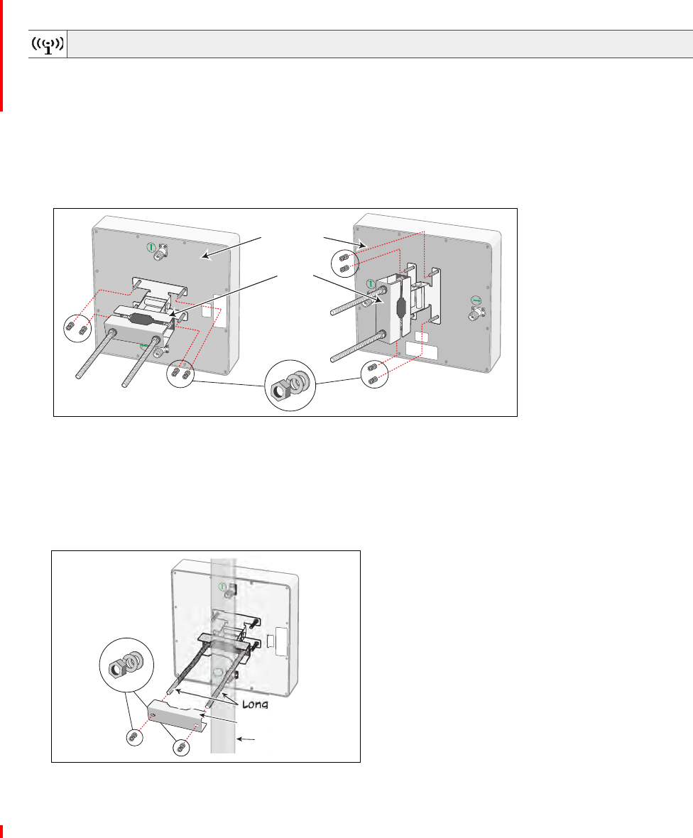
Atta c hing the Ante nna Mo unting Bra c ke t
The fo llo wing ste p s d e sc rib e ho w to a tta c h the mo unting b ra c ke t to the b a c k o f the a nte nna .
1. Atta c h the b ra c ke t fo r a ve rtic a l o r ho rizo nta l insta lla tio n a s sho w n b e lo w. Use fo ur 1/ 4” (6.4 mm) fla t
wa she rs, lo c king nuts, a nd he x nuts to se c ure the b ra c ke t to the a nte nna c ha ssis.
2. Atta c h the a nte nna to a ho rizo nta l o r ve rtic a l ma st in o ne o f two w a ys:
• If yo u c a nno t re a c h a fre e e nd o f the ma st, re mo ve the o ute r ha lf o f the b ra c ke t, p o sitio n the ma st
b e twe e n the two lo ng b o lts a nd re -insta ll the b ra c ke t ha lf. Tig hte n the b ra c ke t using a 5/ 8" (16 m m)
fla t wa she r, lo c king wa she r, a nd he x nut o n e a c h b o lt.
• If a fre e e nd o f the m a st is a c c e ssib le , lo o se n the o ute r ha lf o f the b ra c ke t a nd slid e the a nte nna o nto
the m a st. Tig hte n the b ra c ke t using a fla t wa she r, lo c king wa she r, a nd la rg e he x nut o n e a c h b o lt.
The illustra tio n b e lo w sho ws a ve rtic a l m a st insta lla tio n.
In a c c o rda nc e with FCC re g ula tio ns, do no t install this a nte nna within
26.5" (70 c m) o f a ny p e o p le o r a nima ls.
15
0
15
0
Antenna back
Bracket
Hex nut, locking
washer, and flat
washer
Horizontal mount
Vertical mount
POL
Hex nut, locking
washer, and flat
washer
Mast
Bracket half
Long bolts
as
t
ket
b
o
M
a
Brac
k
Long
POL
POL
Preliminary Draft
AP1130 5-G Hz Dire c tio na l Ante nna Insta lla tio n G uid e 3
MO UNTING THE 5 G HZ DIREC TIO NAL ANTENNA
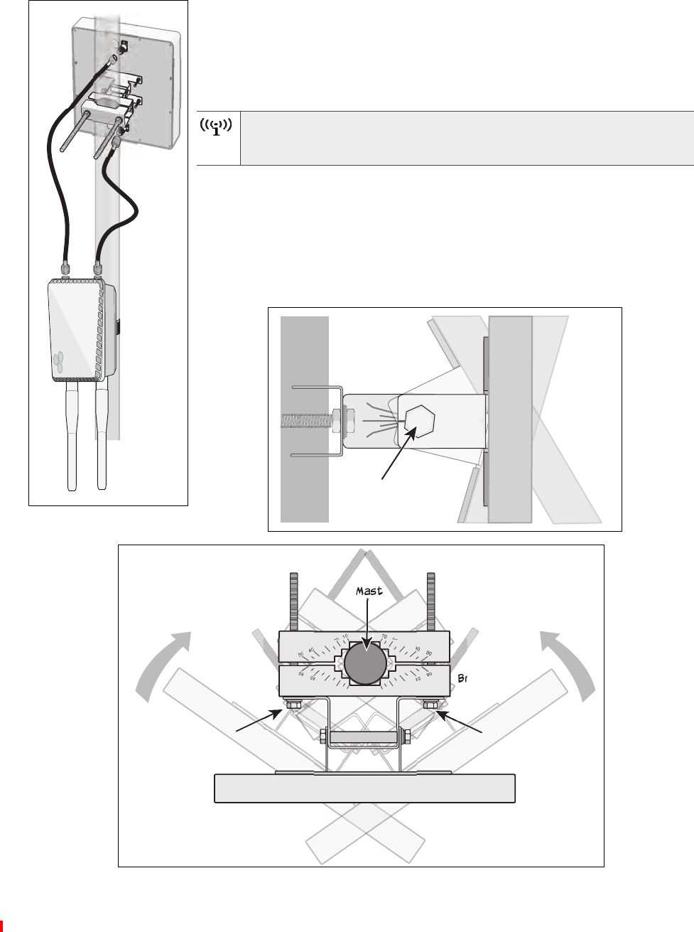
C o nne c ting the Ante nna to the AP
Use the tw o a nte nna c a b le s with N-Ma le to c o nne c t the a nte nna to the AP, a s
sho wn in the illustra tio n a t the le ft. The o p tim um d ista nc e b e tw e e n the d e vic e s
sho uld b e a p p ro xima te ly 3’ (1 m ). If the re is to o m uc h sp a c e b e tw e e n the
d e vic e s, the sig na l will d e g ra d e . It is no t ne c e ssa ry to g ro und the a nte nna .
Alig ning the Ante nna
Two p e o p le a re re q uire d to te st the e le va tio n a nd a lig nme nt fo r m a ximum sig na l
stre ng th. While o ne p e rso n ta ke s re a d ing s o n a n RF te st me te r, the se c o nd
p e rso n ma ke s a d justme nts a s ne c e ssa ry b y lo o se ning the he x nut o n the
mo unting b ra c ke t a nd tilting o r turning the a nte nna c ha ssis. Use the a ng le
ma rking s o n the b ra c ke t a s g uid e line s, a s sho wn in the se illustra tio ns b e lo w to
he lp a lig n the a nte nna ho rizo nta lly a nd ve rtic a lly a s ne e d e d .
Yo u c a n use 2.4 G Hz a nte nnas in a dditio n to the 5 GHz dire c tio na l
a nte nna. Alwa ys insta ll a 50-O hm lo ad te rmina to r o n a ny unuse d
a nte nna c o nne c to r.
0
15
15
Loosen hex nut to
tilt antenna
Mast
Antenna
Bracket
Loosen hex nut to
rotate antenna
Mast
Antenna
Bracket
Loosen hex nut to
rotate antenna
10 20 30 40 50
10 20 30 40 50
10 20 30 40 50
50 40 30 20 10
0
Preliminary Draft

4AP1130 5-G Hz Dire c tio na l Ante nna Insta lla tio n G uid e
De vic e , Po we r, a nd Enviro nme nta l Sp e c ific a tio ns
This se c tio n d e sc rib e s the sp e c ific a tio ns fo r the 5 G Hz d ire c tio na l a nte nna .
• Fre q ue nc y ra ng e : 5150-5850 MHz
• Ba nd wid th: 700 MHz
• G a in: 18 d Bi
• Wid th a nd he ig ht: 10" (254 mm), d e p th: 1.625" (42 m m) witho ut b ra c ke t, 8.75" (222 m m) with b ra c ke t
• We ig ht: 2.54 lb (1.15 Kg )
• Po la riza tio n: ve rtic a l/ ho rizo nta l
• Ma xim um p o we r: 20 Wa tts
• (2) N-typ e fe ma le c o nne c to rs
• Ethe rne t c o nne c to r: a uto se nsing 10/ 100/ 1000 Ba se -T Mb p s; c o mp lia nt with the IEEE 802.3a t Po E sta nd a rd
• Mo unting ma st d ia me te r: 1.5" - 2" (40 - 50 mm)
• O p e ra ting te mp e ra ture : -40° to 140° F (-40° to 60° C )
• Sto ra g e te mp e ra ture : -40° to 176° F (-40° to 80° C )
• Wind surviva b ility: > 165 mp h (266 kp h)
• Enviro nm e nta l c o mp lia nc e : IP67
Fo r the la te st p ro d uc t d o c ume nta tio n, c o mp lia nc e info rma tio n, a nd so ftwa re up d a te s, visit
www.a e ro hive .c o m / sup p o rt.
Preliminary Draft